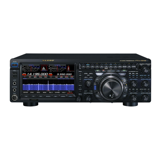
Yaesu FTDX101D Operation Manual
Hf/50mhz transceiver
Hide thumbs
Also See for FTDX101D:
- Operation manual (51 pages) ,
- Service manual (13 pages) ,
- Quick start manual (3 pages)
Table of Contents
Advertisement
Quick Links
Advertisement
Table of Contents

Related Manuals for Yaesu FTDX101D


Summary of Contents for Yaesu FTDX101D
- Page 1 Operation Manual...
- Page 3 About this Manual The FTDX101D is a leading-edge transceiver with a number of new and exciting features, some of which may be unfamiliar to you. In order to gain the most enjoyment and operating efficiency from the FT- DX101D, we recommend that you read this manual in its entirety, and keep it handy for reference as you explore the many capabilities of this new transceiver.
-
Page 4: Table Of Contents
Be sure to study this information to offset frequency ........... 35 maximize the receiver performance TX Clarifier ..........35 of the high-class FTDX101D shortwave To offset the frequency with the transceiver............15 TX Clarifier Adjust receive frequency ..35 Display Indications........16 VC TUNE ............ - Page 5 FC-40 External Automatic Antenna Tuner TFT Screen ..........64 (for Wire Antenna) ......... 108 Text Message Programming on Interconnections to FTDX101D ....108 FH-2 Remote Controller ......64 Setup the FTDX101D ........ 109 Text Input ............. 64 Optional FH-2 Control ........110 On-The-Air RTTY Text Message Playback ..
-
Page 6: General Description
General Description Hybrid SDR configuration In addition to the narrow band SDR receiver that boasts awesome basic performance, the FTDX101D has a hybrid SDR configuration utilizing an integrated direct sampling SDR receiver, which permits visualiza- tion of the spectrum of the entire band in real time. - Page 7 WIDTH and the continuously variable Bandwidth SHIFT features per- mit elimination of interfering signals The WIDTH feature allows the bandwidth to be narrowed by rotating the WIDTH knob. The SHIFT feature, can eliminate interference in one side of the passband. Often, weak signals disappear due to interfering signals (including pile-ups).
-
Page 8: Safety Precautions
Safety Precautions Note beforehand that the company shall not be liable for any damages suffered by the customer or third parties in using this product, or for any failures and faults that occur during the use or misuse of this prod- uct, unless otherwise provided for under the law. - Page 9 Do not allow metallic objects such as wires Refrain from using headphones and ear- and water to get inside the product. phones at a loud volume. This may result in fire, electric shock and equip- Continuous exposure to loud volumes may result ment failure.
-
Page 10: Accessories & Options
FH-2 • Linear Amplifier/AC Power Supply VL-1000/VP-1000 • VL-1000Linear Amplifier Connection Cable CT-178 Please contact YAESU for the following options. • VC-Tuning Unit (for SUB Band) VCT-101 • CW Narrow Filter (C/F: 9.005MHz, B/W: 300Hz, for MAIN Band) XF-128CN • CW Narrow Filter (C/F: 8.900MHz, B/W: 300Hz, for SUB Band) XF-129CN •... -
Page 11: Installation And Interconnections
Construct the antenna and coaxial cable, or use a suitable antenna tuner, to maintain the impedance presented to the FTDX101D antenna connector for an SWR of 1.5 or less. Careful preparation of the an- tenna and/or tuner will permit maximum performance, and protect the transceiver from damage. -
Page 12: Microphone, Headphone, Key, Keyer And Fh-2 Connections
Microphone, Headphone, Key, Keyer and FH-2 Connections φ6.3mm MIC GND FAST (as viewed from front panel) Remote Control Keypad FH-2 EXT SPKR METER EXT ALC RS-232C ANT 1 ANT 2 LINEAR +13.8V TUNER Key-up voltage on the front key jack is approximately +3.3 V DC, and key-down current is approximately 1 mA. Key-up voltage on the rear key jack is approximately +5.0 V DC, and key-down current is approximately 3 mA. -
Page 13: Linear Amplifier Interconnections
Linear Amplifier Interconnections • VL-1000 Linear Amplifier Interconnections Be sure that both the FTDX101D and VL-1000 are turned OFF, and then follow the installation recommenda- tions contained in the bellow illustration. • Refer to the VL-1000 Operating Manual for details regarding amplifier operation. -
Page 14: Rear Panel
A and B AUDIO (MAIN) SIGNAL GND By plugging the FH-2 Remote Control Keypad into this jack, direct access to the FTDX101D CPU is provided for control functions of the contest memo- ry keying, and also frequency and function control. - Page 15 A USB driver is re- [MOX] key on the front panel. Open-circuit voltage quired for remote control from a computer. Down- is 5 VDC, and closed-circuit current is 3 mA. load the driver from the Yaesu website (http://www. yaesu.com). RX OUT (SUB) RS-232C This RCA jack provides output of the RF signal.
-
Page 16: Ssm-75G Microphone Switches
SSM-75G Microphone Switches MUTE PTT Switch MUTE Key Switches Transmit/Receive. While pressing the MUTE key, the receiver audio Press to transmit and release to receive. from the speaker will be muted. DWN / UP Key Microphone The [UP]/[DWN] keys may also be used to manual- Speak into the microphone in a normal tone of ly scan the frequency upward or downward. -
Page 17: Be Sure To Study This Information To Maximize The Receiver Performance Of The High-Class Ftdx101D Shortwave Transceiver
Be sure to study this information to maximize the receiver performance of the high-class FTDX101D shortwave transceiver. Narrow band SDR receiver signal flow and the specific functions that affect receiver performance. Narrow Band SDR Speaker Mixer Roofing Antenna VC-Tune Selector... -
Page 18: Display Indications
Display Indications Meter & Filter images Frequency area Function settings Spectrum Scope Display setting keys Display setting keys Meter Display Meter Operations during Transmission S-Meter S-Meter (MAIN band) (SUB band) Final transistor RF power Output Relative ALC voltage Final amplifier drain voltage temperature Speech compressor level Final amplifier drain current... -
Page 19: Filter Function Display
Filter Function Display Displays the passband status of the DSP filter. The operation of WIDTH, SHIFT, NOTCH, CONTOUR etc. can be observed. The current roofing filter SSB Mode CW Mode RTTY Mode PSK/DATA Mode bandwidth is displayed as a blue line below the filter function display. -
Page 20: Important Receiver Settings
Important Receiver Settings The status of various operations that are important during receive, are shown at the bottom of the display. To change a setting, touch the appropriate location on the display. Important setting items when receiving ANT (Switching the Antenna) The currently used antenna terminal number The IPO (Intercept Point Optimization) function (“ANT 1”... -
Page 21: R.fil (Roofing Filter Switching)
Menu. However, because AGC can have such a profound impact on over- all receiver performance, we generally do not recommend any changes to the AGC Menu se- lections until you are thoroughly familiar with the performance of the FTDX101D. -
Page 22: Scope Display Setting
The frequency span is shown on the horizontal X axis, the vertical Y axis de- picts the signals and their strengths, and the time is represented on the receding Z axis. The FTDX101D operator can intuitively grasp the band and signal conditions at any instant. -
Page 23: Fix
• FIX 3DSS To use Fixed Mode, enter the start frequency of the Switch between the 3DSS display and the waterfall scope. display. The display will change each time it is touched: To adjust the level of the SUB band, press the [SUB] key to make the operation band a SUB band. - Page 24 MULTI HOLD In addition to the scope display, the oscilloscope Temporarily stops the operation of the Scope Dis- and AF-FFT are also presented. play and the Filter Function Display. Touch the dis- Touch again to return to the original screen. play to enter HOLD state, touch it again to restore Scope operation.
-
Page 25: Speed
S.MENU On the SCOPE MENU screen, enter settings related to the Scope Display. Press the [S.MENU] key to display the SCOPE MENU screen. Touch the desired item to set. SCOPE MENU display MULTI knob Operation display MULTI knob S.MENU key SPEED Sets the Scope Display sweep speed. - Page 26 Function Menu Display MULTI key FUNC key Press the [FUNC] key to call up the function screen for setting various functions. The setting menu (page 88) is also called from the function screen. Press again to return to the normal operation screen. Touch a MENU item, or rotate the [MULTI] control knob to make a selection.
-
Page 27: Other On-Screen Indications
Lights in VFO mode. About TFT Displays FTDX101D utilizes a TFT liquid-crystal display. Although TFT liquid-crystal displays are made using very precise technology, they are prone to develop dead pixels (dark dot) or pixels that are always on (bright dot). Please understand that such phenomena do not constitute product defects or malfunctions. -
Page 28: Screen Saver
Screen Saver Font setting for frequency display A Screensaver, to prevent burning of the TFT screen will operate after a set time, if no trans- The height of the frequency display can be varied. ceiver function is operated. 1. Press the [FUNC] key. 2. - Page 29 Note...
-
Page 30: Front Panel Controls & Switches
(grounded) shaft of the plug, resulting in a AUDIO (MAIN) constant “key-down” condition. DOT DASH COMMON This 8-pin jack accepts input from a microphone uti- lizing the traditional YAESU HF transceiver pinout. DOT DASH COMMON MIC GND NC GND FAST Key-up voltage is approximately +3.3 V... -
Page 31: Adjusts The Vox Gain
TUNE This is the ON/OFF switch for the FTDX101D Auto- Pressing this key engages the PTT (Push to Talk) matic Antenna Tuner. circuit to activate the transmitter. Press the [TUNE] key briefly to activate the antenna ZIN/SPOT tuner. Press the [TUNE] key briefly again to disable the antenna tuner. - Page 32 MAIN dial FAST The MAIN dial sets the operating frequency. Pressing this key will change the tuning of the Rotate the MAIN dial knob to tune within the band, MAIN Dial knob and [MULTI] knob (When STEP and begin normal operation. DIAL function is assigned) to a higher step rate.
-
Page 33: Qmb Channel Storage
QMB (Quick Memory Bank) • Confirm the contents of QMB You can display the contents memorized in QMB The current operation status can be stored in a on the screen to check the data. dedicated memory channel (QMB: Quick Memory Bank) with one touch. - Page 34 MODE/SSB/CW MONI Switch the operating mode. Use the Monitor feature to listen to the quality of Press and hold the [MODE] key, then touch the de- your transmitted signal. While activated, the LED sired operating mode. inside this key glows orange. Press it briefly to set the previously selected oper- 1.
-
Page 35: Quick Split Operation
SPLIT • Quick Split Operation The Quick Split feature allows setting a one-touch A powerful capability of the FTDX101D is its offset of +5 kHz as compared to the MAIN band fre- flexibility in Split Frequency operation using the quency, to be applied to the transceiver SUB band MAIN band and SUB band frequency registers. - Page 36 MPVD ring (MULTI PURPOSE VFO OUTER DIAL) Select the MPVD operation by touching one of the keys: MAIN/SUB dial, VC TUNE, CLAR (Clarifier), C.S (Custom Select). Change the function of the MPVD ring The function of the MPVD ring can be changed simply by pressing the key below. CLAR (Clarifier) VC TUNE VC TUNE Operation key...
-
Page 37: Clarifier
Clarifier • TX Clarifier The transmit frequency can be changed without The clarifier is used to adjust the receiver frequency moving the receive frequency of the transceiver. Normally, the clarifier is used to move only the re- of this transceiver to match the other station trans- ceive frequency and compensate for the deviation mit frequency and improve the audio;... -
Page 38: Vc Tune
MAIN band. When operation is on for the Main band. If you also want to use it SUB band. the ring tunes the frequency of the on the SUB band, please contact Yaesu. MAIN band. The VC tune function works only with amateur bands from 1.8 MHz band to... - Page 39 RX (MAIN band) RX (SUB band) Press this key to activate receive on the SUB band Press this key to activate receive on the MAIN band frequency. The LED inside the key will glow green frequency. The LED inside the key will glow green when the transceiver is receiving on the SUB band when the transceiver is receiving on the MAIN band frequency.
-
Page 40: Switching The Operation Of The [Rf/Sql] Knob
MAIN AF, RF/SQL • Switching the operation of the Inner Knob (MAIN AF) [RF/SQL] knob The inner [MAIN AF] knob sets the audio level of 1. Press the [FUNC] key. the MAIN band receiver. 2. Select [OPERATION SETTING]→[GENERAL] Outer Knob (RF/SQL) →... - Page 41 SUB AF, RF/SQL MIC/SPEED, PROC/PITCH Inner Knob (SUB AF) Inner Knob (MIC/SPEED) The inner [SUB AF] knob sets the audio level of the Adjusts the microphone gain (microphone sensitivi- SUB band receiver. ty) (0 to 100) in SSB and AM modes. It is similar to the MAIN Band knob operation.
-
Page 42: Main Band Operation
MAIN Band Operation • Reduces longer duration pulse noise Reduces long duration noise as well as pulse noise. The FTDX101D includes an effective IF Noise Blanker, which can significantly reduce noise 1. Press the [FUNC] key. caused by automotive ignition systems. - Page 43 DNR (Digital Noise Reduction) NOTCH (IF NOTCH Filter) The Digital Noise Reduction (DNR) system is de- The IF NOTCH filter is a highly effective system signed to reduce the level of ambient noise found that allows you to slice out an interfering beat note on the HF and 50 MHz bands.
-
Page 44: Adjust The Gain Of The Contour Circuit
For the SUB band, the same functions as operate. CONT (Contour) • Sets the Bandwidth (“Q”) of the CONTOUR Circuit The Contour filter system provides a gentle per- turbation of the IF filter passband. The Contour is 1. Press the [FUNC] key. set to either suppress, or boost specific frequency 2. - Page 45 APF (Audio Peak Filter) SHIFT, WIDTH During CW operation, when interference or noise is Inner Knob (SHIFT) present, the center frequency is automatically set to IF SHIFT permits moving the DSP filter passband the PITCH frequency, making it easier to hear the higher or lower, without changing the pitch of the desired signal.
- Page 46 Outer Knob (WIDTH) Referring to Figure “B", you can see the default The IF WIDTH tuning system allows you to vary the bandwidth of the SSB mode. width of the DSP IF passband, to reduce or elimi- nate interference. By rotating the [SHIFT] knob to the left, the Moreover, the bandwidth may actually be expanded bandwidth will narrow (see Figure “A”), while from its default setting, should you wish to enhance...
- Page 47 NOTCH, CONT/APF Inner Knob (NOTCH) Rotate the inner [NOTCH] knob to adjust the cen- ter frequency of the IF NOTCH filter. Press the [NOTCH] key to turn the IF NOTCH filter ON or OFF. The null position of the IF NOTCH filter can be ob- served on the display.
-
Page 48: Voice Communications (Ssb And Am)
Voice Communications (SSB and AM) When transmitting in SSB or AM mode The FTDX101D transmit audio circuit can be set to the optimum operating level by individually adjusting the input and output gains of the microphone amplifier. The AMC (Automatic Microphone Gain Control) regulates the microphone audio so that distortion does not oc- cur, even if excessive audio is input. -
Page 49: Speech Processor
Speech Processor RF Power output control The FTDX101D Speech Processor is designed to Turn the [MULTI] knob to adjust the RF power increase “talk power” by increasing the average output. power output of the transmitted SSB signal. 1. Press the [FUNC] key. -
Page 50: Parametric Microphone Equalizer
Parametric Microphone Equalizer The FTDX101D includes a unique Three-Band Parametric Microphone Equalizer that provides precise, in- dependent control over the low, mid and treble ranges in the voice waveform. One group of settings may be utilized when the AMC or speech processor is Off, and an alternate group of settings when the AMC or Speech Processor is On (SSB mode only). - Page 51 Parametric Gain 3-Stage Parametric Equalizer Adjustments (Speech Processor: “OFF”) PRMTRC EQ1 FREQ (Low) “100” (Hz) - “700” (Hz) / OFF Center Frequency PRMTRC EQ2 FREQ (Mid) “700” (Hz) - “1500” (Hz) / OFF PRMTRC EQ3 FREQ (High) “1500” (Hz) - “3200” (Hz) / OFF PRMTRC EQ1 LEVEL (Low) “-10”...
-
Page 52: Voice Memory
Voice Memory The Voice Memory capability of the FTDX101D may be used to store and replay often repeated messag- es. The Voice Memory includes five memories, each capable of storing up to a maximum of 20 seconds of voice audio. -
Page 53: Adjustable Receiver Audio Filter
Adjustable Receiver Audio Filter The FTDX101D incorporates an adjustable receiver audio filter, that affords precision control of the low; lower and upper audio ranges independently. 1. Press the [FUNC] key. 2. Select [RADIO SETTING] . 3. Select the Mode and Menu Item you want to set (see table below). -
Page 54: Using The Automatic Antenna Tuner
Using the Automatic Antenna Tuner The Automatic Antenna Tuner (ATU) is built into each FTDX101D. The ATU is designed to ensure that a 50-Ohm antenna impedance load is presented to the final amplifier stage of the transmitter. Because the FTDX101D ATU is located inside transceiver, it can only adjust the impedance presented to the transceiver end of the coaxial cable feedline. - Page 55 Figure 1 depicts a situation where normal tuning via the ATU has been successfully completed, and the tuning data has been stored in the ATU memory. The antenna system SWR as seen by the transmitter is shown. In Figure 2, the operator has changed frequency, and the “HI-SWR” icon has appeared. The operator presses and holds in the TUNE button for one second to begin impedance matching using the ATU.
-
Page 56: Cw Mode Operation
CW Mode Operation The impressive CW operating capabilities of the “CW FREQ DISPLAY” (page 94). ● By connecting the FTDX101D to a com- FTDX101D permit operating with an Electronic puter, CW can be operated using free or Keyer Paddle, a “Straight Key”, or a computer commercially available software and setting based keying device. -
Page 57: Cw Decode
CW Decode CW Spotting (Zero-Beating) Alphanumeric Morse code can be decoded and “Spotting” (zeroing in on another CW station) is displayed as text on the TFT Panel. a handy technique to ensure the transceiver and the other station are operating precisely on the Interfering signals, noise, propagation phasing, same frequency. -
Page 58: Setting Of The Electronic Keyer
Setting of the Electronic Keyer • Adjusting the Keyer Speed • Selecting the Keyer Operating Mode Keyer speed can be adjusted by rotating the [MIC/ The configuration of the Electronic Keyer may SPEED] knob. be customized independently for the front and rear KEY jacks of the FT DX101D. -
Page 59: Contest Memory Keyer
Contest Memory Keyer The CW message capability of the FTDX101D may be controlled either from the Transceiver Front Panel, or with the optional FH-2 Remote Control Keypad, which plugs into the rear panel REM jack. • Message Memory Five CW memory channels capable of retaining 50 characters each are available (using the PARIS stan- dard for characters and word length). -
Page 60: Checking The Cw Memory Contents
• CHECKING THE CW MEMORY ● ON-THE-AIR CW MESSAGE PLAYBACK CONTENTS 1. Press the [BK-IN] key to enable transmission. When using FH-2, go to step 4. 1. Be sure that Break-in is still turned “OFF” by 2. Press the [FUNC] key. the [BK-IN] key. -
Page 61: Text Memory
• TEXT Memory The five channels of CW message memory (up to 50 characters each) may also be programmed using a text-entry technique. This technique is somewhat slower than sending message directly from the keyer paddle, but accuracy of character spacing is ensured. Be sure to enter the character “}” at the end of the text message. Example 1: CQ CQ CQ DE W6DXC K} (20 characters) The sequential Contest Number (“Count up”) feature is another impressive feature of the CW Memory Keyer. -
Page 62: Checking The Cw Memory Contents
• Checking the CW Memory Contents • ON-THE-AIR CW Message PLAYBack 1. Set the operating mode to CW. 1. Press the [BK-IN] key to enable transmission. 2. Be sure that Break-in is still turned “OFF” by When using FH-2, go to step 4. the [BK-IN] key. -
Page 63: Fm Mode Operation
FM Mode Operation Repeater Operation Tone Squelch Operation The FTDX101D may be operated on 29 MHz and The “Tone Squelch” may be activated to keep the 50 MHz repeaters. receiver silent until an incoming signal modulated with a matching CTCSS tone is received. The 1. -
Page 64: Rtty (Fsk) Operation
RTTY (FSK) Operation The FTDX101D is equipped with a RTTY decode function. The RTTY signal may be easily synchronized by aligning the marker displayed on the TFT screen. Mark frequency (2125 Hz), SHIFT width (170 Hz), and baudot code (US) can be changed in the Setting Menu. -
Page 65: Rtty Decode
Note that text will no longer be displayed for weak signals if the level is increased too much. CQ CQ CQ DE W6DXC W6DXC W6DXC K YAESU FTDX101D 3. The setting is concluded when 4 seconds have elapsed after making the level adjustment. -
Page 66: Rtty Text Memory
RTTY Text Memory Five phrases (up to 50 characters each) frequently used in RTTY exchanges can be entered into the Text Memory, either by operation on the TFT screen, or by using the optional “FH-2” Remote Control Keypad connected to the rear panel REM jack. 5 channels can be memorized, and the memory content can be transmitted by operation on screen or the FH-2. -
Page 67: Data (Psk) Operation
DATA (PSK) Operation The FTDX101D PSK Decode Feature supports both BPSK and QPSK with error correction functions. Easily synchronize PSK by aligning the marker on the TFT display screen. Connecting to a Personal Computer Connect the transceiver and a PC with a commercially available USB cable (A-B) to perform PSK data communications using commercially available software and freeware. -
Page 68: Psk Decode
3. The setting is concluded when 4 seconds have elapsed after making the level adjustment. CQ CQ CQ DE W6DXC W6DXC W6DXC K YAESU FTDX101D Displays content written to the PSK text memory. • Set the data output level for data communi- cations using Menu item “DATA OUT LEVEL”... -
Page 69: Psk Text Memory
PSK Text Memory Five phrases (up to 50 characters each) frequently used in PSK exchanges can be entered into the Text Memory, either by operation on the TFT screen, or by using the optional “FH-2” Remote Control Keypad connected to the rear panel REM jack. 5 channels can be recorded. -
Page 70: Memory Operation
Memory Operation • Erasing Memory Channel Data The contents written to the memory channel may • Memory Storage be erased. 1. Set the frequency, mode, and status, as de- sired. 1. Press the [V M] key. 2. Press the [V M] key. -
Page 71: Check Memory Channel Status
• Check Memory Channel Status Before programming a memory channel, the This key toggles frequency control between VFO current contents of that channel may be verified and the memory system. without the danger of over-writing the channel. The contents of the memory channels can be 1. -
Page 72: Moving Memory Data To The Vfo Register
• Displaying the Memory Tag The “Frequency display” or “Alpha tag display” • Moving Memory Data to the format may be selected. VFO register 1. Press the [V M] key. The contents of the currently selected Memory The memory channel list will be displayed. Channel may be transferred into the VFO register: 2. -
Page 73: Memory Groups
Memory Groups Choosing the Desired Memory Group Memory channels may be listed into as many as six convenient groups, for easy identification If desired, just the memories listed within a partic- and selection. For example: groups for AM BC ular Memory Group, may be recalled. stations, Short-wave broadcast stations, Contest Before performing the operation, set the “MEM frequencies, Repeater frequencies, PMS limits, or... -
Page 74: Vfo And Memory Scanning
VFO and Memory Scanning Either the VFO or the memory channels of the FTDX101D may be scanned, and the receiver will halt scanning on any frequency with a signal strong enough to open the receiver squelch. In the SSB/CW and SSB-based Data modes, the decimal points in the frequency display area will blink and the scanner will slow down (but does not stop). -
Page 75: Programmable Memory Scan (Pms)
Programmable Memory Scan (PMS) To limit scanning (and manual tuning) to a particular frequency range, the Programmable Memory Scan- ning (PMS) feature utilizes nine special-purpose memory pairs (“M-P1L/M-P1U through M-P9L/ M-P9U). The PMS feature is especially useful in helping to observe any operating sub-band limits which apply to your Amateur license class. -
Page 76: Other Functions
Other Functions Band Stack Operation TOT (Time Out Timer) The FTDX101D employs a triple band-stack VFO The “Time-Out Timer” (TOT) shuts the transmitter selection technique that permits storing up to OFF after continuously transmitting for the pro- three favorite frequencies and modes onto each grammed time. -
Page 77: Operation On Alaska Emergency Frequency: 5167.5 Khz (U.s. Version Only)
The FTDX101D is capable of transmitting and receiving on 5167.5 kHz under such emergency conditions. Use the Setting Menu to activate the Alaska Emergency Frequency feature: 2. -
Page 78: Using The Sd Card
4. Touch “START”, the SD card will be initialized. • Note that Yaesu shall not be liable for any Touch “BACK” to cancel the initialization. damages suffered as a result of data loss or 5. -
Page 79: Saving Memory Data And Setting Menu Data
• Saving Memory data and Setting Menu data The Memory Channel data, and the Setting Menu data can be saved to the SD Card: 1. Press the [FUNC] key. 7. Touch the screen to end saving data. 2. S e l e c t [ E X T E N S I O N S E T T I N G ] → [ S D 8. -
Page 80: Reading Memory And Set Menu Data
• Reading Memory and Set Menu data • Display the SD Card Information The Memory and Setting Menu data saved on the The memory free space of the SD card may be SD card may be read to the Transceiver. checked: 1. -
Page 81: Setting Menu
Setting Menu The Menu system of the FTDX101D provides extensive customization capability. The transceiver func- tions can be tailored for the most demanding operators. The Setting Menus are grouped into five specific utilization categories. Comprehensive settings such as: Transmit & Receive, Interference Reduction, Memory, Scan, etc. - Page 82 Menu Function Available Settings (Default: Bold) RADIO SETTING MODE SSB AGC FAST DELAY 20 - 300 - 4000 (20msec/step) AGC MID DELAY 20 - 1000 - 4000 (20msec/step) AGC SLOW DELAY 20 - 3000 - 4000 (20msec/step) LCUT FREQ OFF/100 - 1000 (50Hz/step) LCUT SLOPE 6dB/oct / 18dB/oct HCUT FREQ...
- Page 83 Menu Function Available Settings (Default: Bold) DATA OUT SELECT MAIN / SUB DATA OUT LEVEL 0 - 50 - 100 TX BPF SEL 50-3050 / 100-2900 / 200-2800 / 300-2700 / 400-2600 DATA MOD SOURCE MIC / REAR REAR SELECT DATA / USB RPORT GAIN 0 - 50 - 100...
- Page 84 Menu Function Available Settings (Default: Bold) NUMBER STYLE 1290 / AUNO / AUNT / A2NO / A2NT / 12NO / 12NT CONTEST NUMBER 1 - 999 CW MEMORY 1 TEXT / MESSAGE CW MEMORY 2 TEXT / MESSAGE CW MEMORY 3 TEXT / MESSAGE CW MEMORY 4 TEXT / MESSAGE...
- Page 85 Menu Function Available Settings (Default: Bold) P PRMTRC EQ1 LEVEL -10 - 0 - 10 P PRMTRC EQ1 BWTH 0 - 2 - 10 P PRMTRC EQ2 FREQ OFF / 700 - 1500 (100Hz/step) P PRMTRC EQ2 LEVEL -10 - 0 - 10 P PRMTRC EQ2 BWTH 0 - 1 - 10 P PRMTRC EQ3 FREQ...
- Page 86 HCUT SLOPE RADIO SETTING Function: Sets the slope of the high-frequency - MODE SSB - cutoff audio filter in SSB mode. Available Values: 6dB/oct / 18dB/oct AGC FAST DELAY Default Setting: 6dB/oct Function: Sets the AGC-FAST DELAY voltage SSB OUT SELECT decay characteristics for SSB mode.
- Page 87 RPTT SELECT RADIO SETTING Function: Sets the PTT control for the SSB trans- - MODE AM - mit signal. Available Values: DAKY / RTS / DTR AGC FAST DELAY Default Setting: DAKY Description: Function: Sets the AGC-FAST DELAY voltage DAKY: Controls the SSB transmit signal from the decay characteristics for AM mode.
- Page 88 HCUT SLOPE REAR SELECT Function: Sets the slope of the high-frequency Function: Selects the input jack of the AM signal. cutoff audio filter in AM mode. Available Values: DATA / USB Available Values: 6dB/oct / 18dB/oct Default Setting: DATA Default Setting: 6dB/oct Description: Selects the input jack of the AM sig- nal when “AM MOD SOURCE”...
- Page 89 HCUT SLOPE RADIO SETTING Function: Sets the slope of the high-frequency - MODE FM - cutoff audio filter in FM mode. Available Values: 6dB/oct / 18dB/oct AGC FAST DELAY Default Setting: 18dB/oct Function: Sets the AGC-FAST DELAY voltage FM OUT SELECT decay characteristics for FM mode.
- Page 90 RPTT SELECT RADIO SETTING Function: Sets the PTT control for the FM trans- - MODE PSK/DATA - mit signal. Available Values: DAKY / RTS / DTR AGC FAST DELAY Default Setting: DAKY Description: Function: Sets the AGC-FAST DELAY voltage DAKY: Controls the FM transmit signal from the decay characteristics for PSK/DATA RTTY/DATA jack (pin 3) on the rear panel.
- Page 91 LCUT SLOPE REAR SELECT Function: Sets the slope of the low-frequency Function: Selects the input jack of the DATA sig- cutoff audio filter in DATA mode. nal. Available Values: 6dB/oct / 18dB/oct Available Values: DATA / USB Default Setting: 18dB/oct Default Setting: DATA Description: Selects the input jack of the AM sig- HCUT FREQ...
- Page 92 LCUT FREQ RADIO SETTING Function: Sets the low-frequency cutoff audio fil- - MODE RTTY - ter in RTTY mode. Available Values: OFF / 100Hz - 1000Hz AGC FAST DELAY Default Setting: 300Hz Description: The cutoff frequency can be set at Function: Sets the AGC-FAST DELAY voltage 50 Hz increments between 100 Hz decay characteristics for RTTY mode.
- Page 93 MARK FREQUENCY RADIO SETTING Function: Sets the mark frequency for RTTY - ENCDEC PSK - mode. Available Values: 1275 / 2125 (Hz) PSK MODE Default Setting: 2125Hz Function: Selects the operation mode of the PSK SHIFT FREQUENCY mode. Available Values: BPSK / QPSK Function: Sets the shift width for RTTY mode.
- Page 94 BAUDOT CODE RADIO SETTING Function: Selects the Baudot Code used for the - ENCDEC RTTY - RTTY mode. Available Values: CCITT / US RX USOS Default Setting: US Function: Enables/Disables the RX USOS fea- ture. Available Values: OFF / ON Default Setting: ON Description: When the space symbol is received, the RX USOS function that automati-...
- Page 95 HCUT SLOPE CW SETTING Function: Sets the slope of the high-frequency - MODE CW - cutoff audio filter in CW mode. Available Values: 6dB/oct / 18dB/oct AGC FAST DELAY Default Setting: 18dB/oct Function: Sets the AGC-FAST DELAY voltage CW OUT SELECT decay characteristics for CW mode.
- Page 96 CW WAVE SHAPE CW SETTING Function: Selects the CW carrier wave-form - KEYER - shape (rise/fall times). Available Values: 1ms / 2ms / 4ms / 6ms F KEYER TYPE Default Setting: 4ms (msec) Description: Sets the rise and fall times of the Function: Selects the desired keyer operation keying envelope in CW mode (trans- mode for the device connected to the...
- Page 97 R KEYER TYPE NUMBER STYLE Function: Selects the desired keyer operation Function: Selects the contest number “Cut” for- mode for the device connected to the mat for an imbedded contest number. rear panel KEY jack. Available Values: 1290 / AUNO / AUNT / A2NO / Available Values: OFF / BUG / ELEKEY-A / A2NT / 12NO / 12NT ELEKEY-B / ELEKEY-Y / ACS...
- Page 98 CW MEMORY 3 CW SETTING Function: Selects the registration method for the - DECODE CW - contest keyer “CW MEMORY 3”. Available Values: TEXT / MESSAGE CW DECODE BW Default Setting: TEXT Description: Function: Selects the bandwidth of the AFC fea- TEXT: Use the optional FH-2 or the touch ture.
- Page 99 BEEP LEVEL OPERATION SETTING Function: Sets the beep volume level. - GENERAL - Available Values: 0 - 100 Default Setting: 10 DECODE RX SELECT Description: The higher the setting, the louder the sound becomes. Function: Sets the band to decode in CW, RTTY and PSK mode.
- Page 100 CAT RTS MIC SCAN Function: Configures the CAT RTS port setting. Function: Activates the microphone automatic Available Values: OFF / ON scanning function. Default Setting: ON Available Values: OFF / ON Description: Monitors the computer using the Default Setting: ON RTS signal.
- Page 101 CS DIAL OPERATION SETTING Function: Sets the Operation of MPVD dial when - RX DSP - the [C.S] key is pressed. Available Values: RF POWER / MONI LVL / APF WIDTH DNR LVL / NB LVL / VOX GAIN VOX DELAY / ANTI VOX Function: Sets the bandwidth of the Audio Peak STEP DIAL / MEM CH Filter.
- Page 102 PRMTRC EQ2 FREQ OPERATION SETTING Function: Sets the center frequency for the - TX AUDIO - middle range of the 3 Band Parametric Microphone Equalizer. PROC TYPE Available Values: OFF / 700 - 1500 (Hz) Default Setting: OFF Function: Sets the Speech Processor type. Description: Sets the center frequency for the Available Values: COMP / AMC middle range of the 3 Band Paramet-...
- Page 103 PRMTRC EQ3 BWTH P PRMTRC EQ2 FREQ Function: Selects the width setting (“Q”) for the Function: Selects the center frequency for the high range of the 3 Band Parametric middle range of the 3 Band Parametric Microphone Equalizer. Microphone Equalizer when the AMC Available Values: 0 - 10 or speech processor is activated.
- Page 104 P PRMTRC EQ3 LEVEL OPERATION SETTING Function: Sets the gain for the high range of the - TX GENERAL - 3 Band Parametric Microphone Equal- izer when the AMC or speech proces- HF MAX POWER sor is activated. Available Values: -10 - 0 - 10 (dB) Function: Sets the transmit RF power output of Default Setting: 0 the HF band.
- Page 105 EMERGENCY FREQ TX OPERATION SETTING Function: Enables TX/RX operation on the Alas- - TUNING - ka Emergency Channel, 5167.5kHz. Available Values: OFF / ON SSB/CW DIAL STEP Default Setting: OFF Description: When this Menu Item is set to “ON”, Function: Setting of the MAIN dial tuning speed the spot frequency of 5167.5 kHz will in the SSB and CW mode.
- Page 106 DISPLAY SETTING DISPLAY SETTING - DISPLAY - - SCOPE - MY CALL Function: Programs a Call Sign or Name. Function: Sets the resolution of Spectrum Scope Available Values: Up to 12 alphanumeric charac- display. ters Available Values: HIGH / MID / LOW Default Setting: FTDX101 Default Setting: HIGH Description: Set characters to be displayed on...
- Page 107 SD Memory Card. MONTH FIRMWARE UPDATE Set the date (Month). Function: Update the firmware of the FTDX101D. Description: When a new firmware update for the YEAR FTDX101D is available, go to the YAESU web site to download the Set the date (Year).
- Page 108 EXTENSION SETTING EXTENSION SETTING - CALIBRATION - - RESET - CALIBRATION MEMORY CLEAR Function: Display touch position calibration. Function: Memory reset Description: If the touch position and the opera- Description: Only the information stored in the tion are different, that is touch does Memory Channel is initialized (all not work or another function works, erased).
-
Page 109: Resetting The Microprocessor
Resetting the Microprocessor Memory channels, setting menus, and various settings can be initialized and returned to their factory de- faults. FUNC key EXTENTION SETTING EXTENTION SETTING RESET DATE&TIME MEMORY CLEAR DONE SD CARD MENU CLEAR SOFT VERSION DONE CALIBRATION ALL RESET DONE RESET RESET... -
Page 110: Optional Accessories
Depending on the installation and location of some antennas, it may not be possible to tune to a low SWR. ● Interconnections to FTDX101D After mounting the FC-40, connect the cables from the FC-40 to the ANT and TUNER jacks on the rear panel of the FTDX101D Transceiver. Antennna Antenna Cable (supplied with FC-40) -
Page 111: Setup The Ftdx101D
The optional FC-40 Automatic Antenna Tuner provides automatic tuning of a coaxial line to present nomi- nal 50-ohm impedance to the FTDX101D’s ANT jack. Before tuning can begin, the FTDX101D must be configured to recognize that the FC-40 is being used. Configuration is done using the Setting Menu •... -
Page 112: Optional Fh-2 Control
Optional FH-2 Control With the optional remote-control keypad FH-2 voice messages may be recorded and transmitted (Voice Memory). The FH-2 is also the control of the Contest Memory Keyer during CW operation. ● SSB / AM / FM modes have five voice memory channels (20 seconds each) for storage and playback, of voice recordings (page 50). -
Page 113: Specifications
Specifications General Tx Frequency Ranges: 1.8 MHz - 54 MHz (Amateur bands only) 70 MHz - 70.5 MHz (UK Amateur bands only) Rx Frequency Range: 30 kHz - 75 MHz (operating) 1.8 MHz - 29.699999 MHz (Specified performance, Amateur bands only) 50 MHz - 53.999999 MHz (Specified performance, Amateur bands only) 70 MHz - 70.499999 MHz (Specified performance, UK Amateur bands only) Emission Modes:... -
Page 114: Receiver
Receiver Circuit Type: Double Superheterodyne Intermediate Frequencies: 1 st: 9.005 MHz (MAIN), 8.9000 MHz (SUB) 2 nd: 24 kHz (MAIN/SUB) Sensitivity (TYP): SSB/CW (BW: 2.4 kHz/10 dB S+N/N) 1.8 MHz - 30 MHz 0.16 µV (AMP2 “ON”) 50 MHz - 54 MHz 0.125 µV (AMP2 “ON”) 70MHz - 70.5MHz 0.16µV (AMP2 “ON”) -
Page 115: Index
Index +13.8V ............. 13 Digital Noise Reduction ........41 3DSS ............... 21 Digital NOTCH Filter ........41 DISP ..............22 Display Indications ........... 16 DNF ..............41 About TFT Displays ......... 25 DNR ..............41 ACC ..............13 Accessories ............8 Adjustable Receiver Audio Filter ...... - Page 116 Labeling Memories .......... 70 Rear Panel ............12 LEVEL ............. 23 REM ..............12 LINEAR ............13 Repeater Operation ......... 61 Linear Amplifier Interconnections ....11 Resetting the Microprocessor ......107 LOCK ............... 30 Reversing the Keyer Polarity ......56 R.FIL ..............
- Page 117 USB ..............13 USB Jack ............28 Using the SD Card ........... 76 VC TUNE ............36 VFO Scanning ..........72 Voice Communications ........46 Voice Memory ..........50 VOX ..............29 VOX anti-trip sensitivity ........29 VOX Delay Time ..........29 VOX GAIN ............
-
Page 118: Yaesu Limited Warranty
D. The Limited Warranty is valid only in the country/region where this product was originally purchased. E. During the Warranty Period, YAESU MUSEN will, at its sole option, repair or replace (using new or re- furbished replacement parts) any defective parts within a reasonable period of time and free of charge. - Page 119 OF EQUIPMENT AND PROPERTY, AND ANY COSTS OF RECOVERING, PROGRAMMING OR RE- PRODUCING ANY PROGRAM OR DATA STORED IN OR USED WITH THE YAESU PRODUCT. Some Countries in Europe and some States of the USA do not allow the exclusion or limitation of inciden- tal or consequential damages, or a limitation on how long an implied warranty lasts, so the above limita- tion or exclusions may not apply.
- Page 120 6125 Phyllis Drive, Cypress, CA 90630, U.S.A. Telephone: (714) 827-7600 z Changes or modifications to this device that are not expressly approved by YAESU MUSEN could void the user’s authorization to operate this device. z This device complies with part 15 of the FCC Rules. Operation is subject to the following two conditions: ( 1 ) This device may not cause harmful interference, and ( 2 ) this device must accept any interference including received, interference that may cause undesired operation.
- Page 121 EU Declaration of Conformity We, Yaesu Musen Co. Ltd of Tokyo, Japan, hereby declare that this radio equipment FTDX101D is in full compliance with EU Radio Equipment Directive 2014/53/EU. The full text of the Declaration of Conformity for this product is available to view at http://www.yaesu.com/jp/red ATTENTION –...
- Page 122 Copyright 2019 YAESU MUSEN CO., LTD. All rights reserved. No portion of this manual may be reproduced without the permission of YAESU MUSEN CO., LTD. YAESU MUSEN CO., LTD. Tennozu Parkside Building 2-5-8 Higashi-Shinagawa, Shinagawa-ku, Tokyo 140-0002 Japan YAESU USA 1904D-BS 6125 Phyllis Drive, Cypress, CA 90630, U.S.A.