Table of Contents
Advertisement
TR
TR 641 top2
641 0 100
TR 642 top2
642 0 100
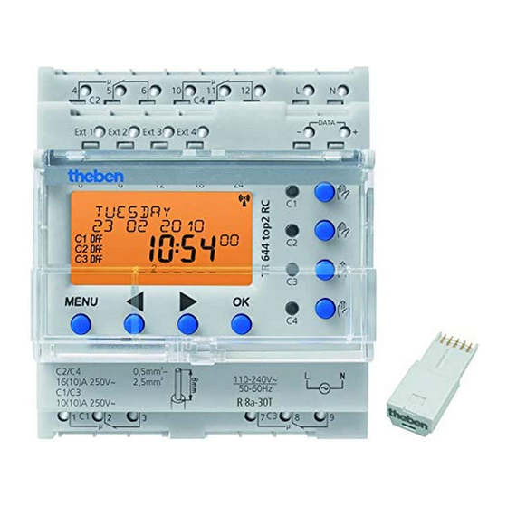
TR 644 top2
644 0 100
TR 641 top2 RC
641 0 300
TR 642 top2 RC
642 0 300
TR 644 top2 RC
644 0 300
Installation and
operating instructions
Digital time switch with annual and
astronomical program
D
GB
F
I
E
NL
Other languages are available at
www.theben.de
µ
µ
L
N
4
10
5
6
11
12
C2
C4
DATA
Ext1
Ext2
Ext3
Ext4
-
+
0
6
18
12
24
C1
C1
C2
C2
C3
C4
C3
E
MENU
OK
C4
0,5mm -
2
C2/C4
L
N
110-240V~
2,5mm
2
16(10)A 250V~
50-60Hz
C1/C3
10(10)A 250V~
R8a - 30T
C1
C3
7
1
2
3
8
9
µ
µ
TR 644 top2 RC
309 429 01
GB
top2 RC–DCF antenna
Antenna top2 RC-GPS
N
L
L
Advertisement
Table of Contents

Related Manuals for Theben TR 644 top2


Summary of Contents for Theben TR 644 top2
- Page 1 641 0 300 DATA Ext1 Ext2 Ext3 Ext4 TR 642 top2 RC 642 0 300 TR 644 top2 RC 644 0 300 top2 RC–DCF antenna Antenna top2 RC-GPS Installation and operating instructions MENU Digital time switch with annual and 0,5mm -...
-
Page 2: Table Of Contents
Contents OPTIONS Basic safety instructions Set astro programs Display and keys/operating instructions 4-channel extension module Connection/installation Enter PIN code Overview of menu selection External output Initial start-up Time switch programs, astronomical programs 9 Time signal reception with top2 antenna OBELISK top2 memory card PROGRAM LAN module Program switching time again in the... -
Page 3: Basic Safety Instructions
Basic safety instructions WARNING Danger of death through electric shock or fire! Installation should only be carried out by a qualified electrician! • The device is designed for installation on DIN top hat rails (in accordance with EN 60715) •... -
Page 4: Display And Keys/Operating Instructions
µ µ Screen and keys Operating DATA Ext1 Ext2 Ext3 Ext4 instructions top2 RC-DCF or Program display 1. Read text lines GPS antenna con- Text represents query Programmed nected display switching times Time display µ µ Weekday and Weekdays from 1 to 7 Date display DATA Astronomical... -
Page 5: Connection/Installation
Connection/installation WARNING Warning, danger of death through electric shock! Must be installed by qualified electrician! Disconnect power source. Cover or shield any adjacent live components. Ensure device cannot be switched on! 45° cable Check power supply is disconnected. ... -
Page 6: Overview Of Menu Selection
Overview of menu selection MENU PROGRAM SIMULATION TIME/DATE CHOOSE CHANNEL CHOOSE CHANNEL TIME STANDARD EXTRA START YEAR DATE PROGRAM P0 PROGRAM 2010 P1–P16 2010 SUMMER- START MONTH WINTER RULE CHECK–MODIFY– 2010 WEEKDAY DELETE START DAY NUMBER DELETE 2010 FORME DATE... - Page 7 MANUAL OPTIONS CHOOSE CHANNEL ASTRO PERMANENT ON EXT INPUT PERMANENT OFF OPERATING HOURS OVERRIDE ON LANGUAGE TIMER SHORT FACTORY TERM CIRCUIT SETTINGS HOLIDAY LCD- ACTIVATE EXTRA INFO PROGRAM ILLUMINATION RANDOM EXTENSION MODULE EM 4 * only with RC devices...
-
Page 8: Initial Start-Up
Initial start-up ENGLISH SUMMER Set date, time and summer/ WINTER EUROPE WEST FORME DATE winter time rule SUMMER WINTER YEAR EUROPE EAST 2010 Press required key and display follows SUMMER WINTER 21 01 2010 on screen (see figure). CANADA MONTH SUMMER... -
Page 9: Time Switch Programs, Astronomical Programs
With the digital 365-day time switch TR 641 top2 (1-channel time switch), TR 642 top2 (2-channel time switch), TR 644 top2 (4-channel time switch) the time switch or astro programs can be pro- grammed and switched optionally for each channel. -
Page 10: Program Switching Time Again In The Standard Program
Time switch program Program switching time again in the standard program Example: Switch on sports hall lighting from Mon–Fri, 7:30 to 12:00 hrs Press MENU. PROGRAM is displayed. Confirm by pressing OK. CHOOSE CHANNEL is displayed. Confirm CHANNEL 1 by pressing OK. STANDARD PROGRAM P0 is displayed. ... - Page 11 MENU PROGRAM CHOOSE CHANNEL STANDARD EXTRA EXTRA DELETE PROGRAM PROGRAM 1 PROGRAM 2 CHANNEL 1 SWITCH TIME PULSE CYCLE HOUR ON 7.30 MINUTE EVERY DAY MONDAY TUESDAY COPY SAVE ADD TUESDAY SAVED SAVE SAVED...
-
Page 12: Request/Change/Delete Switching Time
Request/change/ delete switching time MENU PROGRAM Press MENU. PROGRAM CHOOSE is displayed. CHANNEL Confirm by pressing OK. STANDARD PROGRAM Confirm CHANNEL 1 by pressing CHECK- DELETE MODIFY- P0 ALL Confirm STANDARD PROGRAM DELETE P0 by pressing OK. SWITCH TIME ... -
Page 13: Delete Switching Times
Delete all switching times in MENU the standard program PROGRAM CHOOSE CHANNEL Press MENU. PROGRAM is displayed. STANDARD Confirm by pressing OK. PROGRAM Confirm CHANNEL 1 by pressing OK. CHECK- DELETE MODIFY- P0 ALL STANDARD PROGRAM P0 is displayed. DELETE CONFIRM ... -
Page 14: Pulse Time Programming
Pulse time programming Example: Switch on pause signal on Monday 8:05 hrs for 5 sec Press MENU. PROGRAM is displayed. Confirm by pressing OK. CHOOSE CHANNEL is displayed. Confirm CHANNEL 1 by pressing OK. STANDARD PROGRAM P0 is displayed. ... - Page 15 MENU PROGRAM CHOOSE CHANNEL STANDARD PROGRAM SWITCH TIME PULSE CYCLE HOUR ON 8.05 EVERY DAY MONDAY MINUTES SAVE COPY SAVE SECONDS SAVED ADD TUESDAY SAVED PULSE LENGTH IN MINUTES PULSE LENGTH IN SAVE Length 5 sec SECONDS SAVED...
-
Page 16: Programme Cycle Time
Programme cycle time In addition to switch-on and switch-off times (switching time) and short time pulses (pulse) cycle times (cycle) can also be programmed. The pulse length (+ pulse pause) is limited to 17 hrs, 59 min, 59 sec • Cycle times refers to cyclically repetitive time functions such as fan controls, urinal rinses etc. Example: Switch on water rinsing Monday from 8:00 to 20:30 hrs every 15 min for 20 sec (8:00 –8:00... -
Page 17: Standard And Special Programs
Standard program and extra programs • The standard program P0 (weekly program with switching times, pulse and cycle times or astro- nomical program) is always active however has the lowest priority and can be superimposed by the extra programmes P1–P16. •... - Page 18 – Chinese New Year (20 days before ... 20 days after the Chinese New Year) – Date with serial pattern (Time limit series): Start and end are set and the start repeated according to an adjustable number of days (at the latest after 200 days) –...
- Page 19 – Date with serial pattern (Time limit series) as from November 2010 to be carried out successively every 2nd week Start on Monday 01.11.2010 at 0:00 hrs; End on Monday 08.11.2010 at 0:00 hrs, repeat start after 14 days – Date dependent on the weekday etc. each month on the 1st weekend from Saturday 06:00 hrs to Sunday 18:00 hrs;...
- Page 20 – Fixed switch-offs (e.g. nighttime interruption) and switch-ons can also be entered as weekly program in order to superimpose the astronomical times entirely or partially. Example: The standard program switches on the street lighting in dependence of the astro times. A nighttime interruption is programmed from 23:00 hrs to 04:00 hrs. Extra program 1 is active within the date range from April 30, 12:00 hrs until May 12:00 hrs.
-
Page 21: Simulation
SIMULATION MENU PROGRAM SIMULATION During the simulation it is a channel-related total CHOOSE request. All channel switching entered (standard and CHANNEL special program, switching times, pulse and cycle START YEAR programs) are displayed in the time sequence in which 2010 they are applied. -
Page 22: Time/Date
TIME/DATE In the menu TIME/DATE the TIME, DATE, SUMMER WINTER RULE, WEEKDAY NUMBER, EASTER RULE etc. can be entered/changed in the submenus. Press MENU using select DATE/TIME and follow the indications on the display. MENU TIME/DATE ... -
Page 23: Manual
MANUAL In the MANUAL menu manual switch functions are applied. In the submenus MANUAL, PERMANENT ON/OFF, TIMER SHORT TERM CIRCUIT, HOLIDAY, RANDOM as well as ACTIVATE EXTRA PROGRAM the manual switching can be activated/programmed. Press MENU using select MANUAL and follow the indications on the display. ... -
Page 24: Manual And Permanent Switching
C2/C4 240V~ 110-240V~ 110-240V~ 110-240V~ 110-240V~ 110-240V~ 2,5mm 2,5mm 2,5mm 2,5mm 2,5mm 110-240V~ TR 641 top2 RC TR 642 top2 RC TR 644 top2 RC 2,5mm 16(10)A 250V~ 60Hz 50-60Hz 50-60Hz 50-60Hz 50-60Hz 50-60Hz 50-60Hz C1/C2 C1/C2 C1/C2 C1/C3 C1/C2... -
Page 25: Options
OPTIONS In the menu OPTIONS the submenus ASTRO, EXTERNAL INPUT, OPERATING HOUR, LANGUAGE, PIN, LCD ILLUMINATION, EXTENSION MODULE (only for RC devices), FACTORY SETTINGS as well as INFO can be requested. Press MENU using select OPTIONS and follow the indications on the display. ... -
Page 26: Set Astro Programs
Set ASTRO program MENU OPTIONS ... if a time switch program is active. ASTRO Press MENU using select OPTIONS and ASTRO SETTING follow the instructions on the display. CHOOSE CHANNEL You will automatically be taken to the setting for ... - Page 27 In the OPTIONS submenu ASTRO it is possible – At sunset it switches on, at sunrise it switches off (e.g.: street lighting) after a channel has been changed to astro pro- – Evenings off, mornings on gram – to request or change astro times, offset, At sunset it switches off, at sunrise it switches astro mode as well as position (location).
- Page 28 MENU OPTIONS ASTRO ASTRO POSITION SETTINGS COUNTRY COORDINATES COUNTRY LATITUDE GERMANY NORTH CITY LATITUDE STUTTGART EAST SAVED TIME ZONE UTC + 1 H SAVED CHOOSE CHANNEL ASTRO TIMES OFFSET ASTRO MODE CHANGE TO TIME SWITCH PROGRAM OFFSET...
-
Page 29: 4-Channel Extension Module
OPTIONS in the time switch (see operating PRESS SET TASTE ON THE EM4 manual for the module EM 4 top2). MODULE EM 4 ACTIVE Enter PIN code The PIN-Code is set in OPTIONS via the menu. If you have forgotten your PIN call the Theben Hotline. -
Page 30: External Output
EXTERNAL OUTPUT For each channel an EXTERNAL INPUT (see figure) can be set with different functions. Press MENU using select EXT INPUT and follow the indications on the display. 3 submenus can be selected: Inactive, push button (function), switch (function) –... - Page 31 MENU OPTIONS ASTRO EXTERNAL OPERATING INPUT HOURS CHOOSE CHANNEL INACTIVE PUSH SWITCH BUTTON SAVED OVERRIDE TIMER SHORT STAIRCASE PERMANENT ON or PERMANENT TERM CIRCUIT LIGHT OFF or EXTRA PROGRAM SAVED ON or OFF EARLY CUTOUT SAVED or RESETABLE...
-
Page 32: Time Signal Reception With Top2 Antenna
Time signal received with suitable antenna top2 RC-DCF or antenna top2 RC-GPS • Only use the antenna top2 RC-DCF (907 0 410) or antenna top2 RC-GPS (907 0 610) for the 365-day time switch. • By connecting the antenna top2 RC-DCF or GPS the time switch can be automatically syn- chronised via the DCF or GPS time signal. - Page 33 NOTE When connecting ensure correct polarity. Lay separate cable for antenna power supply. Observe maximum cable length of 100 m. Align the radio antenna so that the green LED flashes once a second. A maximum of 5 365-day time switches can be connected to one antenna. Setting time zones µ...
-
Page 34: Obelisk Top2 Memory Card
OBELISK top2 memory card Copy OBELISK Time switch This copies the switching program (all standard and special programs) and optionally all time Use memory card (see fig.) switch (e.g. Position, offset, external input, time format etc..) from the memory card in the ... -
Page 35: Lan Module
LAN module EM LAN top2 Service address/Hotline Service address With the LAN module EM LAN top2 (649 0 900) Theben AG remote access to the 365-day time switch is Hohenbergstr. 32 possible via a LAN. OBELISK top2 data (switch 72401 Haigerloch... -
Page 36: Technical Data
Technical Data 641 0 100 641 0 300 642 0 100 642 0 300 644 0 100 644 0 300 Operating voltage / Frequency 110 – 240 V~, -15 %/+10 % , 50 - 60 Hz Power consumption (typ.) 1,3 W 2,0 W 1,7 W 2,5 W...