
Related Manuals for Toshiba RAS-M10U2MUVG-E


Summary of Contents for Toshiba RAS-M10U2MUVG-E
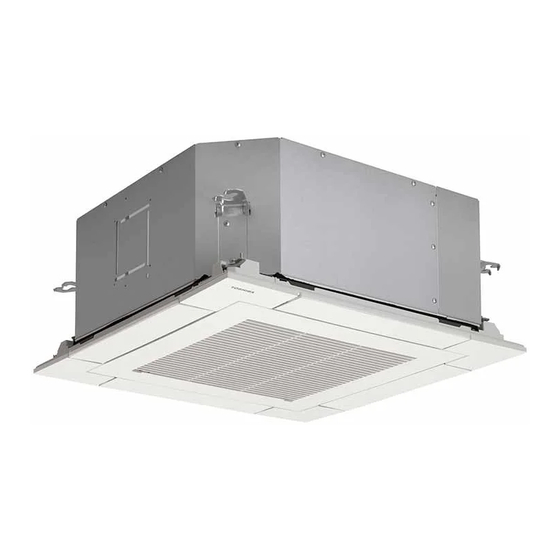
- Page 1 FILE NO. A10-1819 SERVICE MANUAL AIR-CONDITIONER (MULTI-SPLIT TYPE) INDOOR UNIT <Compact 4-way Cassette type> RAS-M10U2MUVG-E (TR) RAS-M13U2MUVG-E (TR) RAS-M16U2MUVG-E (TR) PRINTED IN JAPAN, Apr., 2018 ToMo...
-
Page 2: Table Of Contents
CONTENTS 1. SAFETY PRECAUTIONS ..................3 2. SPECIFICATIONS ....................13 3. REFRIGERANT R32 ....................14 4. CONSTRUCTION VIEWS (EXTERNAL VIEWS) ............ 17 5. WIRING DIAGRAMS ....................19 6. SPECIFICATIONS OF ELECTRICAL PARTS ............20 7. REFRIGERANT CYCLE DIAGRAM ............... 21 8. -
Page 3: Safety Precautions
• The qualified service person is a person who installs, repairs, maintains, relocates and removes the air conditioners made by Toshiba Carrier Corporation. He or she has been trained to install, repair, maintain, relocate and remove the air conditioners made by Toshiba Carrier Corporation... - Page 4 Definition of Protective Gear When the air conditioner is to be transported, installed, maintained, repaired or removed, wear protective gloves and ‘safety’ work clothing. In addition to such normal protective gear, wear the protective gear described below when undertaking the special work detailed in the table below.
- Page 5 Warning Indications on the Air Conditioner Unit [Confirmation of warning label on the main unit] Confirm that labels are indicated on the specified positions If removing the label during parts replace, stick it as the original. WARNING WARNING ELECTRICAL SHOCK HAZARD ELECTRICAL SHOCK HAZARD Disconnect all remote Disconnect all remote electric power supplies before servicing.
- Page 6 Precaution for Safety The appliance shall be installed in accordance with national wiring regulations. Capacity shortages of the power circuit or an incomplete installation may cause an electric shock or fire. DANGER Before carrying out the installation, maintenance, repair or removal work, be sure to set the circuit breaker to the OFF position.
- Page 7 WARNING Before starting to repair the air conditioner, read carefully through the Service Manual, and repair the air conditioner by following its instructions. ∗ Only qualified service person ( 1) is allowed to repair the air conditioner. Repair of the air conditioner by unqualified person may give rise to a fire, electric shocks, injury, water leaks and/or other problems.
- Page 8 If, in the course of carrying out repairs, it becomes absolutely necessary to check out the electrical parts with the electrical parts box cover of one or more of the indoor units and the service panel of the outdoor unit removed in order to find out exactly where the trouble lies, wear insulated heat-resistant gloves, insulated boots and insulated work overalls, and take care to avoid touching any live parts.
- Page 9 This Air Conditioner has adopted a refrigerant HFC R32 or R410A. Be sure to check the refrigerant type for outdoor unit to be combined. In case that refrigerant type is R32, this unit uses a flammable refrigerant. If refrigerant leaks and comes in contact with fire or heating part, it will create harmful gas and there is risk of fire.
- Page 10 When the refrigerant gas leaks, find up the leaked position and repair it surely. If the leaked position cannot be found up and the repair work is interrupted, pump-down and tighten the service valve, otherwise the refrigerant gas may leak into the room. When gas touches to fire such as fan heater, stove or cocking stove, it may generate noxious gases, causing a fire though the refrigerant gas itself is innocuous.
- Page 11 ∗ ∗ Only a qualified installer ( 1) or qualified service person ( 1) is allowed to install the air conditioner. If the air conditioner is installed by an unqualified individual, a fire, electric shocks, injury, water leakage, noise and/or vibration may result. Before starting to install the air conditioner, read carefully through the Installation Manual, and follow its instructions to install the air conditioner.
- Page 12 (*1) Refer to the “Definition of Qualified Installer or Qualified Service Person” Specifications Sound pressure level (dB(A)) Weight (kg) Model Main unit (Ceiling panel) Cooling Heating ∗ ∗ RAS-M10U2MUVG-E 15 (2.5) ∗ ∗ RAS-M13U2MUVG-E 15 (2.5) ∗ ∗ RAS-M16U2MUVG-E 15 (2.5) ∗...
-
Page 13: Specifications
Standard filter (Long life filter) Air filter Usable indoor temperature rang (Cooling / Heating) 21 ~ 32˚C / 0 ~ 28˚C Name Toshiba Carrier Co.,Ltd Manufacturer Adress, city, country 336 Tadehara, Fuji-shi, Shizuoka-ken 416-8521 JAPAN Connecting cable More than H07RN-F or 60245 IEC66 (1.5 mm... -
Page 14: Refrigerant R32
3. REFRIGERANT R32 This air conditioner adopts a new HFC type refrigerant (R32) which does not deplete the ozone layer. 1. Safety Caution Concerned to Refrigerant R32 Be sure that water, dust, the former refrigerant or the former refrigerating oil is not mixed into the refrigerating cycle of the air conditioner with refrigerant R32 during installation work or service work. - Page 15 <Caution items> 1) The opposite side dimension of the air-conditioner’s flared nut using R32 and the shape of the charge port are the same as those of R410A. 2) Be careful not to charge refrigerant by mistake. Should the different type of refrigerant mix in, be sure to recharge the refrigerant 3) Do not mix the other refrigerant or refrigerating oil with the refrigerant.
- Page 16 4. Tools Tools exclusive for R410A (The following tools for R410A are required.) : R410A tools available : Partly unavailable, : R410A tools unavailable Installation/service tools Applicability to R32 air Applicability to R22 air conditioner or not conditioner or not Tools / Equipment specification 1 Flare tool...
-
Page 17: Construction Views (External Views)
4. CONSTRUCTION VIEWS (EXTERNAL VIEWS) 4-1. RAS-M10U2MUVG*, M13U2MUVG* – 17 –... - Page 18 4-2. RAS-M16U2MUVG* – 18 –...
-
Page 19: Wiring Diagrams
5. WIRING DIAGRAMS – 19 –... -
Page 20: Specifications Of Electrical Parts
6. SPECIFICATIONS OF ELECTRICAL PARTS Indoor unit Model RAS- M10∗ M13∗ M16∗ Fan motor ICF-340D60-1 Louver motor MSBPC20F04 Float switch FS-0218-102 Drain pump motor MDP-1401 TA sensor Lead wire length: 818 mm Vinyl tube TC sensor Ø6 size lead wire length: 500 mm Vinyl tube (Black) TCJ sensor Ø6 size lead wire length: 400 mm Vinyl tube (Red) –... -
Page 21: Refrigerant Cycle Diagram
7. REFRIGERANT CYCLE DIAGRAM RAS-M10,13U2MUVG* INDOOR UNIT Distributor (Strainer incorporated) TCJ sensor Heat exchanger Strainer TC sensor Connecting pipe Connecting pipe Thickness : 0.8mm Thickness : 0.8mm Ø9.52 Ø6.35 Sectional shape of heat insulator OUTDOOR UNIT RAS-M16U2MUVG* INDOOR UNIT Distributor (Strainer incorporated) TCJ sensor Heat... -
Page 22: Control Block Diagram
8. CONTROL BLOCK DIAGRAM 8-1. Connection of Wired Remote Controller Wired remote controller (Max. 2 units) Display LCD Function setup Display LED Key switch DC5V Remote controller Power circuit communication circuit Indoor unit Indoor control P .C. board (MCC-1643) DC20V Remote controller EEPROM communication circuit... - Page 23 8-2. Connection of Wireless Remote Controller Kit Indoor unit Indoor control P .C. board (MCC-1643) DC20V Remote controller EEPROM communication circuit DC5V TA sensor DC12V TC sensor TCJ sensor Louver Driver Float input motor Drain Wireless/ pump Occupancy sensor Indoor fan motor Serial send/ receive circuit...
-
Page 24: Operation Description
9. OPERATION DESCRIPTION 9-1. Outline of Air Conditioner Control .................... 25 9-2. Operation Description ........................ 26 1. Basic operation ........................26 1-1. Operation control ....................... 26 1-2. When power supply is reset ..................27 1-3. Operating mode selection when performing 2-room operation........27 1-4. -
Page 25: Outline Of Air Conditioner Control
9-1. Outline of Air Conditioner Control This air conditioner is a capacity-variable type air • Detection of inverter input current and current conditioner, which uses DC motor for the indoor fan release operation motor and the outdoor fan motor. • Over-current detection and prevention operation The DC motor drive circuit is mounted to the indoor unit. -
Page 26: Operation Description
9-2. Operation Description Item Operation flow and applicable data, etc. Description 1. Basic 1-1. Operation control operation Receiving the user's operation condition setup, the operation statuses of indoor/outdoor units are controlled. 1) The operation conditions are selected by the remote controller as shown below. 2) A signal is sent by ON button of the remote controller. -
Page 27: When Power Supply Is Reset
Item Operation flow and applicable data, etc. Description 1. Basic 1-2. When power supply is reset operation 1) Distinction of outdoor unit (continued) When the power supply is reset, the outdoors are distinguished and the control is selected according to the distinguished result. 2) Setting of indoor fan speed and existence of air direction adjustment Air speed (rpm)/ Based on EEPROM data, select setting of the indoor fan speed and the... -
Page 28: Automatic Capacity Control (Ga Control)
Item Operation flow and applicable data, etc. Description 1. Basic 1-5. Automatic capacity control (GA control) operation 1) Based on the difference between Ta and Ts, the operation frequency is (continued) instructed to the outdoor unit. 2) Cooling oparation Every 90 seconds, the room temperature difference between temperature detected by Ta and Ts and the varied room temperature value are calculated to obtain the correction value of the frequency command and then the present frequency command is corrected. -
Page 29: Auto Operation
Item Operation flow and applicable data, etc. Description 1. Basic 1-7. AUTO operation operation Remote controller Control outline (continued) command AUTO • COOL/HEAT operation mode is Ta: Room temp. automatically selected by Ta, Ts and To for Ts: Setup temp. operation. -
Page 30: Indoor Fan Motor Control
Item Operation flow and applicable data, etc. Description 2. Indoor fan 1) Operation with (HH), (H+), (H), (L+), (L) or [AUTO] mode is carried out by the HH > H+ > H > L+ > L motor command from the remote controller. >... - Page 31 Item Operation flow and applicable data, etc. Description 2. Indoor fan Revolution speed of indoor fan (rpm) Selection of motor High ceiling type by RAS-M10U2MUVG-E control changing COOL HEAT Standard High Ceiling(1) High Ceiling(3) (continued) CODE(FC)[5d] or SW501 on P.C. board.
-
Page 32: Capacity Control
Item Operation flow and applicable data, etc. Description 2. Indoor fan Cool air discharge preventive control In D and E zones, the motor 1) In heating operation, the indoor fan is controlled based on the detected priority is given to air control temperature of Tc sensor or Tcj sensor. -
Page 33: Release Protective Control By Temperature Of Indoor Heat Exchanger
Item Operation flow and applicable data, etc. Description 4. Release Freeze preventive control (Low temperature release) protective 1) The cooling operation (including Dry operation) is performed as follows control by based on the detected temperature of Tc sensor or Tcj sensor. temperature When [J] zone is detected for 6 minutes (Following figure), the commanded of indoor... -
Page 34: Intermittent Operation Control For Indoor Fans Of The Indoor Unit At Thermo-Off Side In Heating Operation
7. Intermittent Operation Control for Indoor Fans of the Indoor Unit at Thermo-off Side in Heating Operation While heating operation is executed in two rooms, if room temperature reached the setup temperature in one room and thermo-off occurred, the following operations start. (Refer to the figure below.) 1.The indoor unit of the room (A room) in which thermo-off did not occur starts a continuous operation with the setup number of revolution. -
Page 35: Louver Control
Item Operation flow and applicable data, etc Description 8. Louver 1) Louver position setup control • When the louver position is changed, the position once moves to the most downward position then return to the set position. • The louver position can be set up in the following operation range. In cooling/dry operation In heating/fan operation When louvers is in the... - Page 36 Item Operation flow and applicable data, etc Description Selection of Swing mode 8. Louver <<Selection of Swing mode>> can be set up by wired control * Select the louver swing type from the standard swing, dual swing or remote controller. (Continued) cyclic swing.
- Page 37 Item Operation flow and applicable data, etc Description Louver lock can be set <<Louver lock (Louver fix)>> 8. Louver up by wired remote control * The direction of the louver can be locked individually. controller. (Continued) Carry out the setting operation while the indoor unit is stopped. (Turn off the air conditioning unit before starting the setting operation.) Before setting Louver lock...
-
Page 38: Filter Sign Display (Except Wireless Type)
Item Operation flow and applicable data, etc Description 8. Louver • If there is the locked louver in the unit, [ ] goes on the remote controller For the setting control screen. operation, refer to (Continued) • While the following controls are performed, the louvers operate even if [Louver lock] of executing the louver lock. -
Page 39: Additional Operation
Item Operation flow and applicable data, etc Description 1. QUIET mode 13. Additional Quiet mode is the system which, control the revolving speed of Operation When the [QUIET] button is pushed, the fan of the indoor unit will indoor fan to work constantly at be restricted the revolving speed at speed L until the [QUIET] speed L. -
Page 40: Remote-A Or B Selection
Item Operation flow and applicable data, etc Description 14. Remote-A Setting the remote controller 1. Purpose or B To separate using of remote control for each indoor unit in case of 2 This operation is to operate only selection air conditioner are installed nearly. one indoor unit using one remote Remote Control B Setup. -
Page 41: Short Timer
Item Operation flow and applicable data, etc Description 16. Short In the normal condition, after switching one circuit Purpose Timer breaker, 3-minute delay time for compressor is set for the To start the unit immediately for the maintenance of the unit. purpose of testing, trial...etc, short timer can be used. -
Page 42: Auto Restart Function
9-3. Auto Restart Function This indoor unit is equipped with an automatic restarting function which allows the unit to restart operating with the set operating conditions in the event of a power supply being accidentally shut down. The operation will resume without warning three minutes after power is restored. This function is not set to work when shipped from the factory. -
Page 43: How To Cancel The Auto Restart Function
2. How to Cancel the Auto Restart Function To cancel auto restart function, proceed as follows : Repeat the setting procedure : the unit receives the signal and beeps three times. The unit will be required to be turned on with the remote controller after the main power supply is turned off. •... -
Page 44: Wireless Remote Controller
9-4. Wireless remote controller 1. Remote controller • Illustration of LCD shown below is for explanation. It may differ from the actual LCD. Set louver button (FIX) Push this button to adjust the airflow direction. (A receiving beep is heard.) It cannot be operated by holding down the button. -
Page 45: Names And Functions Of Indications On Wireless Remote Controller
2. Names and functions of indications on wireless remote controller Display (COMFORT SLEEP) display All indications, except for clock time indication, are Indicated during the OFF timer operation that indicated by pushing the START/STOP button. automatically adjusts the room temperature and the fan speed. -
Page 46: Signal Receiving Unit
3. Signal receiving unit The signal receiving unit is attached to the indoor unit. Temporary operation button Signal receiving part The signal sent from the remote controller is received. Display lamp One of displays flashed while a trouble occurs. When the display lamp flashes, refer to “Before asking for repair work”. -
Page 47: How To Diagnose The Trouble
10. HOW TO DIAGNOSE THE TROUBLE The pulse motor circuits are mounted to both indoor and outdoor units. Therefore, diagnose troubles according to the trouble diagnosis procedure as described below. (Refer to the check points in servicing written on the wiring diagrams attached to the indoor/outdoor units.) Table 10-1 Troubleshooting Procedure... - Page 48 10-2. Primary Judgment To diagnose the troubles, use the following methods. 1) Judgment by flashing LED of the signal receiving unit 2) Self-diagnosis by service check remote controller 3) Judgment of trouble by every symptom Firstly use the method 1) for diagnosis. Then, use the method 2) or 3) to diagnose the details of troubles. 10-3.
- Page 49 10-4. Self-Diagnosis by Remote Controller (Check Code) 1. If the lamps are indicated as shown B to E in Table 10-3-1, execute the self-diagnosis by the remote controller. 2. When the remote controller is set to the service mode, the indoor controller diagnoses the operation condition and indicates the information of the self-diagnosis on the display of the remote controller with the check codes.
- Page 50 10-4-2. Caution at Servicing 1. After servicing, press the [CLR] button to return to the normal mode. 2. After servicing by the check code, turn off breaker of the power supply, and turn on breaker of the power supply again so that memory in the microcomputer returns the initial status. However, the check codes are not deleted even if the power supply is turned off because they are stored in the fixed memory.
- Page 51 Judgment and action Check Check Block Cause of operation conditioner Remarks code code status Outdoor Inverter over-current All off Displayed when Even if trying operation again, all P.C. board protective circuit trouble is detected. operations stop immediately. : Replace operates. (Short P.C.
- Page 52 Judgment and action Check Check Block Cause of operation conditioner Remarks code code status Others Return serial signal Operation Flashes when 1. Repeat Start and Stop with interval of (including has been sent when continues trouble is approx. 10 to 40 minutes. (Code is compressor) operation started, but detected on...
- Page 53 10-5. Judgment of Trouble by Every Symptom 10-5-1. Indoor Unit (Including Remote Controller) (1) Power is not turned on (Does not operate entirely) <Primary check> 1. Is the supply voltage normal? 2. Is the normal voltage provided to the outdoor unit? 3.
- Page 54 (2) Power is not turned on though Indoor P.C. board is replaced <Confirmation procedure> Turn on power supply. Is wired correctly to white and black lead Does operation lamp flash? Correct wiring. wires of terminal board? To item of “Power is not turned on”. –...
- Page 55 (3) Only the indoor motor fan does not operate <Primary check> 1. Is it possible to detect the power supply voltage (AC220–240V) between on the terminal block? 2. Does the indoor fan motor operate in cooling operation? (In heating operation, the indoor fan motor does not operate for approximately 10 minutes after it is turnedon, to prevent a cold air from blowing in.) Power off.
- Page 56 (4) Troubleshooting for remote control The unit does not beep at all. Press [ OPERATION lamp on indoor button. unit is not indicated. Is transmission mark indicated? Press RESET button on remote control with Is the signal tip of pencil. receiving unit exposed to direct sunlight? Does indoor unit...
- Page 57 10-6. How to Check Simply the Main Parts 10-6-1. How to Check the P.C. Board (Indoor Unit) (1) Operating precautions 1) When removing the P.C. board, be sure to shut off the power supply breaker. 2) When removing the P.C. board, hold the edge of the P.C. board and do not apply force to the parts. 3) When connecting or disconnecting the connectors on the P.C.
- Page 58 (3) Check procedures Table 10-6-1 Turn off the power supply breaker Check whether or not the fuse (F01) Impulse voltage was applied or the and remove the P.C. board is blown. indoor fan motor short-circuited. assembly from electronic parts base. Remove the connecting cables from the terminal block.
- Page 59 11-6-2. P .C . Board Layout EEPROM IC503 Remote controller CN41 Indoor/Outdoor inter-unit cable Float CN67 CN34 sensor CN102 sensor CN101 sensor CN104 DC fan output CN210 CN61 Drain Louver pump CN510 DISP(CN72) CN504 Wireless remote control or CHK(CN71) External input/output Occupancy sensor (UART) CN521 CN214 (White)
- Page 60 10-6-3. Indoor Unit (Other Parts) Room temp. (TA) sensor Disconnect the connector and measure the resistance value with tester. Heat exchanger (TC) sensor (Normal temp.) Temperature 20°C 25°C 30°C 40°C 10°C Sensor TA, TC (kΩ) 20.7 12.6 10.0 Remote controller Refer to 10-5-1.
-
Page 61: How To Replace The Main Parts
11. HOW TO REPLACE THE MAIN PARTS WARNING CAUTION Be sure to stop operation of the air conditioner before Be sure to put on gloves during working time; work and then turn off switch of the breaker. otherwise an injury will be caused by a part etc. No. - Page 62 No. Part name Procedure Remarks 1. Detachment Adjust corner cap 1) Remove the air intake grille. (Refer to 1 of 2) Loosen the fixing screws on the adjust corner cap. (Ø4 × 12, 4 pcs.) Adjust corner 3) Slide the adjust corner cap to outside to remove it. Screw 2.
- Page 63 No. Part name Procedure Remarks 1. Detachment Control P.C. board 1) Remove the electric parts cover. (Refer to 1 of 2) Remove connectors which are connected from the control P.C. board to the other parts and then remove wiring from the clamp. NOTE Unlock the lock of the housing part and then remove the connector.
- Page 64 No. Part name Procedure Remarks 1. Detachment Drain pan 1) Remove the ceiling panel and the electrical parts covers. Fixing screws (Refer to items -1 and -1.) 2) Remove the wiring cover. (Fixing screw Ø4 × 8, 3pcs.) 3) Remove the wiring fixing plate. (Fixing screw Ø4 ×...
- Page 65 No. Part name Procedure Remarks 1. Detachment Drain pump 1) Remove the drain pan. (Refer to -1.) 2) Remove the drain pump connector (CN504: 2P, White) connected to the control P.C. board and remove the lead wires from the clamp. 3) Remove the fixing screws to remove the drain pump.
- Page 66 No. Part name Procedure Remarks 1. Detachment Fan motor 1) Remove the turbo fan, electric parts cover, wiring cover Shoulder screws (Black) and wiring fixing plate. (Refer to -1-2, -1-3.) 2) Remove the fan motor connector (CN210, White, 7P) Motor lead wire cover connected to the control P.C.
- Page 67 No. Part name Procedure Remarks 1. Detachment TA sensor Adjust position of the tube so that the tube of TA sensor will be included in the cover. 1) Remove the panel, electric parts box cover, wiring cover and wiring fixing plate. (Refer to -1-2, -1-3.)
- Page 68 No. Part name Procedure Remarks 1. Detachment Heat exchanger 1) Recover refrigerant gas. 2) Remove the refrigerant pipe at indoor unit side. 3) Remove the drain pan. (Refer -1.) 4) Disconnect the heat exchanger sensor (TC1, TC2, TCJ), from the control P.C. board, and then remove their lead wires from the clamp.
-
Page 69: Exploded Views And Parts List
12. EXPLODED VIEWS AND PARTS LIST 12-1. RAS-M10U2MUVG-E, M13U2MUVG-E, M16U2MUVG-E 206, 207 TOSHIBA TOSHIBA 208, 209 PRESET TEMP MODE COMFORT QUIET SLEEP SWING HI-POWER 214, 215 212, 213 TIMER SLEEP FILTER CLOCK – 69 –... - Page 70 Q’ty/Set Location RAS-M RAS-M RAS-M Part No. Description 10U2 13U2 16U2 MUVG-E MUVG-E MUVG-E 43120277 FAN, ASSY TURBO 43122165 BELL MOUTH 43172259 PAN ASSY, DRAIN 4312C161 MOTOR, FAN 43F97212 4314J577 REFRIGERATION CYCLE ASSY REFRIGERATION CYCLE ASSY 4314J578 43149498 SOCKET 43149504 SOCKET 43149497 SOCKET...
- Page 71 12-2. RAS-M10U2MUVG-TR, M13U2MUVG-TR, M16U2MUVG-TR 206, 207 TOSHIBA TOSHIBA 208, 209 PRESET TEMP MODE COMFORT QUIET SLEEP SWING HI-POWER 214, 215 212, 213 TIMER SLEEP FILTER CLOCK – 71 –...
- Page 72 Q’ty/Set Location RAS-M RAS-M RAS-M Part No. Description 10U2 13U2 16U2 MUVG-TR MUVG-TR MUVG-TR 43120277 FAN, ASSY TURBO 43122165 BELL MOUTH 43172259 PAN ASSY, DRAIN 4312C161 MOTOR, FAN 43F97212 4314J577 REFRIGERATION CYCLE ASSY REFRIGERATION CYCLE ASSY 4314J578 43149498 SOCKET 43149504 SOCKET 43149497 SOCKET...
- Page 73 E-Parts 404,405,406 PC BOARD ASSY CN22 SW501 CLAMP,UP CLAMP,DOWN TERMINAL,2P TERMINAL BLOCK,3P,20A SENSOR ASSY,SERVICE(F6) SENSOR,SERVICE Q’ty/Set RAS-M Location Part No. Description 10U2MUVG-E 13U2MUVG-E 16U2MUVG-E 10U2MUVG-TR 13U2MUVG-TR 16U2MUVG-TR 43050425 SENSOR ASSY, SERVICE, TC(F6) 43160565 TERMINAL BLOCK, 3P, 20A 43160568 TERMINAL, 2P 4316V660 PC BOARD ASSY 4316V663...
- Page 74 Ceiling panel RBC-UM21PG (W)-E TOSHIBA" " Mark Location Q’ty/Set Part No. Description RBC-UM21PG(W)-E 43109441 GRILLE, AIR INLET 43180361 AIR FILTER 4342D001 MOTOR, LOUVER, MSBPC20F04 43107296 OUTLET, AIR FORM 43107297 OUTLET, AIR FORM 43122166 LOUVER ASSY 4310A142 COVER, PANEL ASSY 4310A143...
- Page 75 Wireless remote controller kit RBC-AX32UM (W)-E Location Q’ty/Set Part No. Description RBC-AX32UM(W)-E 4316V616 PC BOARD ASSY, REMOTE RECIEVER 43162088 COVER, WRS 43108036 COVER, PANEL WRS 43160665 LEAD 43408061 COVER, WIRELESS 43166018 REMOTE CONTROLLER, WIRELESS, WH-L11SE 43F83071 HOLDER, REMOTE, CONTROLLER – 75 –...
- Page 76 Occupancy sensor TCB-SIR41UM-E Location Q’ty/Set Part No. Description TCB-SIR41UM-E 43162088 COVER, WRS 43108037 COVER, PANEL WRS 43160666 LEAD 43408062 COVER, SENSOR 43469067 THERMOSTAT – 76 –...
-
Page 77: Appendix
13. APPENDIX Wired Remote Controller (RB-RWS21-E) setup 1. Test run setup <Procedure> Perform setting while the air conditioner stops. Push the [ MENU] button to display the menu screen. Field setting menu(1/2) 1.Test mode 2.Register service info. Push and hold the [ MENU] button and the 3.Alarm history 4.Monitor function... - Page 78 Using the Service monitor with the [ MONITOR] button during the test mode Room A 12:00 Test Cool Mode Fan Speed Push the [ MONITOR] button Monitor Function Code Data 0024 Return Refer to “3. Monitor function” for details. 2. Function selection setup Perform the advanced settings for the air conditioner.
- Page 79 Function selection item No. (FC) list Item Description At shipment 01 Filter sign lighting timer 0000: None 0001: 150H 0002 : 2500H 0002: 2500H 0003: 5000H 0004: 10000H 02 Dirty state of filter 0000: Standard 0000: Standard 0001: High degree of dirt (Half of standard time) 06 Heating temp shift 0000: 0 °C 0001: +1 °C...
- Page 80 3. Monitor function The sensor temperature or operational status of indoor unit, outdoor unit, or remote controller can be monitored. Push the [ ] / [ ] button to select “4. Monitor function” on the “Field setting menu” screen, then push the Monitor function “...
- Page 81 TOSHIBA CARRIER CORPORATION 72-34 Horikawa-cho, Saiwai-ku, Kawasaki-shi, Kanagawa 212-8585, JAPAN Copyright © 2018 TOSHIBA CARRIER CORPORATION, ALL Rights Reserved.