Table of Contents
Advertisement
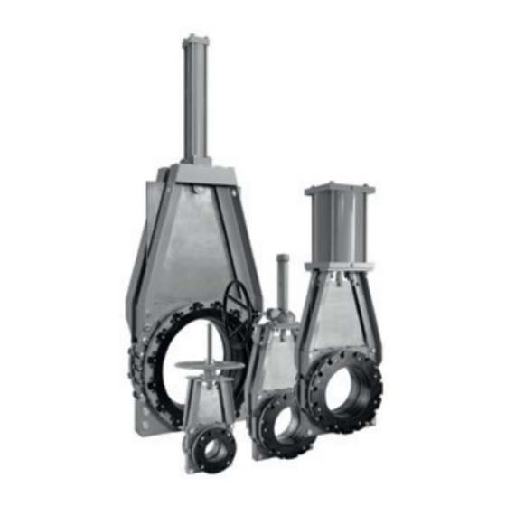
Clarkson Slurry Knife Gate ValVeS
KGA And KGA+
installation and maintenance instructions
ClarKSOn KGa+
ValVe aSSeMBlieS
kGa+ index
1. General information ...................................... 2
2. initial inspection ............................................ 2
3. installation instructions ................................ 3
4. Operation ....................................................... 4
5. lockouts ........................................................ 6
6. General maintenance.................................... 6
7. Spare parts .................................................... 7
8. Storage ........................................................... 8
9. Sleeve replacement ...................................... 9
10. Secondary seal replacement ...................... 10
12. field replacement of gates ......................... 15
15. lifting ........................................................... 17
16. Manual handwheel actuator assembly ...... 18
17. Bevel gear actuator assembly .................... 18
18. air cylinder actuator assembly................... 19
19. Hydraulic cylinder actuator assembly ....... 19
emerson.com/FinalControl
kGa index
20. General information .................................... 20
21. initial inspection .......................................... 20
22. installation instructions .............................. 21
23. Operation ..................................................... 22
24. lockouts ...................................................... 24
25. General maintenance.................................. 24
26. Spare parts .................................................. 25
27. Storage ......................................................... 26
28. Sleeve replacement .................................... 27
29. Wiper replacement ...................................... 28
31. field replacement of gates ......................... 32
33. lifting ........................................................... 34
34. Manual handwheel actuator assembly ...... 35
35. Bevel gear actuator assembly .................... 35
36. air cylinder actuator assembly................... 36
37. Hydraulic cylinder actuator assembly ....... 36
this instruction manual provides installation,
operation and maintenance recommendations
for both the Clarkson KGa and Clarkson KGa
Plus (KGa+) slurry knife gate valves. the KGa
was first introduced in the 1970's and the
KGa+ design was introduced in 2010. While
both products are very similar, the KGa+ offers
additional features with resulting differences in
maintenance procedures and parts lists.
the first section covers the KGa+, the second
the KGa. Please refer to the KGa+ or KGa
section for complete instructions.
kGa+ and kGa identified
the KGa+ is easily identified from the KGa by
several prominent features:
Mating flanges: the KGa has slotted mating
flanges to mate with aSMe B16.5/150 pipe
flanges in sizes above nPS 8 (Dn 200). the
KGa+ features full flange design in all size
and can be adapted to many different flange
drillings.
© 2017 emerson. all rights reserved.
VCioM-06601-en 17/09
Advertisement
Table of Contents

Related Manuals for Emerson KGA


Summary of Contents for Emerson KGA
-
Page 1: Table Of Contents
7. Spare parts ............ 7 the first section covers the KGa+, the second 8. Storage ............8 the KGa. Please refer to the KGa+ or KGa 9. Sleeve replacement ........9 section for complete instructions. 10. Secondary seal replacement ...... 10 kGa+ and kGa identified 11. -
Page 2: General Information
(patent pending). simplified housing assembly: housing spacers 1. examine entire valve and report any retainer flanges found on the KGa have been eliminated from damage or discrepancies immediately. the KGa+ allowing for an easier disassembly / 2. Sleeves: visually examine the sleeves assembly process. -
Page 3: Installation Instructions
When equipped with 1. the KGa+ is installed with the gate in the retainer flanges, the elastomer coated fully open position with the sleeves inserted retainer flange functions as the gasket into the housing halves. -
Page 4: Operation
See Section See figures 2 and 3. ‘installation instructions for splash guard’. note: it is normal for the KGa+ to discharge 6. all valves should be operated within the media during opening and closing cycles. design pressure and temperature ranges. - Page 5 8. Certain processes contain hazardous and/or otherwise unstable media. Care should be settings may damage or lockup the valve. 12. Clarkson KGa+ valves are position seated taken in these circumstances to ensure the operator is aware of the specific health and and should never be torque seated.
-
Page 6: Lockouts
KGa+. if provided, functioning properly. note: it is normal for the KGa+ valve to the open-closed lockout brackets are designed to resist the normal valve operating discharge media during opening and thrust. -
Page 7: Spare Parts
Spacer bar is also visible. nPS 3 - 16 (Dn 80 - 400). new gates for the KGa+ sizes nPS 3 - 16 (Dn 80 - 400) are 1. When ordering replacement parts for a not interchangeable with the prior design Clarkson product or cylinder operator, KGa and older gates will not fit the KGa+. -
Page 8: Storage
DO NOT store a KGA+ with a spring to extend (fail close) in the open position. -
Page 9: Sleeve Replacement
(2) retainer flanges (if required), figures of a housing affected by wear and retainer flange bolts and nuts (if required). KGa+ nPS 30 - 60 (Dn 750 - 1500), use usage. if housing is not within the maximum retainer segmented retainer flanges. -
Page 10: Secondary Seal Replacement
Clarkson Slurry Knife Gate ValVeS KGA+ 10. turn the valve over so the installed sleeve 3. for ease of reassembly, using a permanent fiGure 9 is on the flat surface. marker, draw a line on the gate face along example of a segmented retainer 11. - Page 11 Clarkson Slurry Knife Gate ValVeS KGA+ reassembly 11. ‘Stretch’ the frame / actuator assembly fiGure 11 1. if valve has been removed from pipe, lift with respect to the housing by pulling (not Secondary valve to vertical position, refer to lifting, lifting) the frame / actuator assembly to seal retainer...
-
Page 12: Disassembly And Assembly Instructions
10. loosen the secondary seal retainer plate disassembly bolts. 1. Before working on the KGa+ valve, verify 11. remove the gate by lifting it out of the that the valve is in the open position. if it secondary seal. - Page 13 Clarkson Slurry Knife Gate ValVeS KGA+ Visual inspection of parts prior to reassembly use a disc grinder or belt sander to remove tap the edges of the housings to align the 1. Check and ensure all housing interior rough surfaces. take particular care on the internal sleeve bores to within ”...
- Page 14 Clarkson Slurry Knife Gate ValVeS KGA+ 11. apply a small amount of recommended 17. Cycle valve to full open position and check fiGure 13 lubricant to the two tapered faces of the the gate position using the data in the ‘sharp end’...
-
Page 15: Field Replacement Of Gates
Clarkson Slurry Knife Gate ValVeS KGA+ 12 Field replaCeMent oF Gates 2. inspect the gate for sharp edges or fiGure 14 excessive damage. Some scoring will disassembly occur in normal use. if the gate has been bent beyond 1. replacement of the gate can be ”... -
Page 16: Installation Instructions For Splash Guard
13 installation instruCtions For splash guard. This can result in valve failure. splash Guard (b7 option) note: it is normal for the KGa+ to discharge 1. remove the splash guard, mounting media during opening and closing cycles. hardware, and gasket from the valve crate. -
Page 17: Lifting
Small Clarkson all valves can be lifted using the frame (yoke) KGA air and or hydraulic actuated valves may be assembly as the lift point. DO nOt uSe equipped with eyebolts. These may only be used lOCKOut BraCKetS tO lift ValVe. -
Page 18: Manual Handwheel Actuator Assembly
Clarkson Slurry Knife Gate ValVeS KGA+ 16 Manual handWheel aCtuator asseMbly - Mh travel limit Hex screw travel limit Hex washer travel limit Cap nut Set screw Handwheel thrust washer Base mounting screw/washer/nut Stem nut base adapter plate screw/washer/nut Woodruff key... -
Page 19: Air Cylinder Actuator Assembly
Clarkson Slurry Knife Gate ValVeS KGA+ 18 air Cylinder aCtuator asseMbly - aC air cylinder actuator Cylinder mounting washer/nut yoke (clevis) Clevis pin w/cotter pin frame (yoke) Housing/frame (yoke) screw/washer/nut 19 hydrauliC Cylinder aCtuator asseMbly - hC Hydraulic cylinder actuator... -
Page 20: General Information
KGa should be installed with the gate be operated at conditions outside these in the open position. exercise caution when parameters. -
Page 21: Installation Instructions
1. the KGa is installed with the gate in the fully into the pipeline. When equipped with open position with the sleeves inserted into retainer flanges, the elastomer coated the housing halves. -
Page 22: Operation
See Section See figures 2 and 3. ‘installation instructions for splash guard’. note: it is normal for the KGa to discharge 6. all valves should be operated within the media during opening and closing cycles. design pressure and temperature ranges. - Page 23 Care should be settings may damage or lockup the valve. taken in these circumstances to ensure the 12. Clarkson KGa valves are position seated and operator is aware of the specific health and should never be torque seated. Do not use safety risks associated with that medium.
-
Page 24: Lockouts
KGa. if provided, functioning properly. note: it is normal for the KGa valve to the open-closed lockout brackets are designed to resist the normal valve operating discharge media during opening and thrust. -
Page 25: Spare Parts
Spacer bar is also visible. nPS 3 - 16 (Dn 80 - 400). new gates for the 1-repair kit KGa+ sizes nPS 3 - 16 (Dn 80 - 400) are not interchangeable with the prior design 1. When ordering replacement parts for a KGa and older gates will not fit the KGa+. -
Page 26: Storage
DO NOT store a KGA with a detrimental as long as the valve is kept spring to extend (fail close) in the open position. -
Page 27: Sleeve Replacement
(if required). 2. Check the bore diameter for unusual or KGa nPS 30 - 60 (Dn 750 - 1500), use segmented retainer flanges. refer to excessive wear. if found, valve housing the Clarkson certified parts list for the may require replacement. -
Page 28: Wiper Replacement
(Dn 250) and larger. larger diameter valves are note: certified Clarkson elastomer parts from supplied with segmented (multipart) retainer emerson are laser-etched with part number, flanges. if your valve has segmented retainer date of manufacture, the Clarkson brand flanges, take note of the special sections. - Page 29 64.11 1628.39 disassembly 10. remove the gate. 1. Before working on the KGa valve, verify that 11. remove the wiper retainer mounting the valve is in the open position. if it is not, screws, the retainer plates and wipers move it to the open position.
- Page 30 Clarkson Slurry Knife Gate ValVeS reassembly 6. inspect the gate for sharp edges or 7. install new sleeves and retainer flanges excessive damage. Some scoring will 1. lay the first housing half face down on (if used) per Section 5 (one-piece retainers) occur in normal use.
- Page 31 Clarkson Slurry Knife Gate ValVeS 10. Press the gate into the valve housing 15. rattle the gate. it should be mostly fiGure 13 assembly until the mark drawn on the gate disengaged from the sleeves. the outboard reaches the top of the retainer plate or edges of the gate should be free and the gate reaches approximately dimension a, center still partially engaged in between...
-
Page 32: Field Replacement Of Gates
Clarkson Slurry Knife Gate ValVeS 31 Field replaCeMent oF Gates replace. if straightening is performed, fiGure 14 use considerable care to minimize marks Caution on gate surface. Scores or other distress Since this procedure may be performed with the marks may be cleaned up with a belt valve in an active pipeline, plant standard safety sander. -
Page 33: Installation Instructions For Splash Guard
Clarkson Slurry Knife Gate ValVeS note: it is normal for the KGa to discharge 13. ‘Stretch’ the frame / actuator assembly 2. Cut the gasket material into four pieces with respect to the housing by pulling (not that will form the rectangular dimensions media during opening and closing cycles. -
Page 34: Lifting
(yoke) assembly as the lift point. DO nOt uSe KGA air and or hydraulic actuated valves may be equipped with eyebolts. These may only be used lOCKOut BraCKetS tO lift ValVe. insert... -
Page 35: Manual Handwheel Actuator Assembly
Clarkson Slurry Knife Gate ValVeS 34 Manual handWheel aCtuator asseMbly - Mh travel limit Hex screw travel limit Hex washer travel limit Cap nut Set screw Handwheel thrust washer Base mounting screw/washer/nut Stem nut base adapter plate screw/washer/nut Woodruff key adapter plate Stem nut Stem assembly... -
Page 36: Air Cylinder Actuator Assembly
Clarkson Slurry Knife Gate ValVeS 36 air Cylinder aCtuator asseMbly - aC air cylinder actuator Cylinder mounting washer/nut yoke (clevis) Clevis pin w/cotter pin frame (yoke) Housing/frame (yoke) screw/washer/nut 37 hydrauliC Cylinder aCtuator asseMbly - hC Hydraulic cylinder actuator Cylinder mounting washer/nut yoke (clevis) Clevis pin w/cotter pin frame (yoke)