
Related Manuals for Siemens FDCI222


Summary of Contents for Siemens FDCI222
- Page 1 FDCI222, FDCIO222, FDCIO224 Input module, input/output module Technical Manual Building Technologies 007023_k_en_-- 2017-11-22 Control Products and Systems...
- Page 2 Issued by: Siemens Switzerland Ltd. Building Technologies Division International Headquarters Theilerstrasse 1a CH-6300 Zug Tel. +41 58 724-2424 www.siemens.com/buildingtechnologies Edition: 2017-11-22 Document ID: 007023_k_en_-- © Siemens Switzerland Ltd, 2004 2 | 50 Building Technologies 007023_k_en_-- Fire Safety 2017-11-22...
-
Page 3: Table Of Contents
Structure and function ................. 15 Overview ....................15 3.1.1 Details for ordering ..............16 3.1.2 Product version ES ..............17 Setup ......................17 3.2.1 Input module FDCI222 ..............18 3.2.2 Input/output modules FDCIO222 and FDCIO224 ......19 3.2.3 Printed circuit board view ............20 3.2.4 LEDs ..................21 Function ....................22 3.3.1... - Page 4 Planning ....................32 Compatibility ....................32 Defining the place of installation ..............33 Defining the type of monitoring and input configuration ......34 Defining the output configuration ..............35 Filling out the configuration sheet ............... 36 Environmental influences ................36 Mounting / Installation ................37 Mounting on a U-rail ..................
-
Page 5: About This Document
Incorrect installation can take safety devices out of operation unbeknown to a layperson. Goal and purpose This document contains all information on the input module FDCI222 and the input/output modules FDCIO222 and FDCIO224. Following the instructions consistently will ensure that the product can be used safely and without any problems. - Page 6 About this document Applicable documents Target groups The information in this document is intended for the following target groups: Target group Activity Qualification Product Manager Is responsible for information Has obtained suitable specialist passing between the manufacturer training for the function and for the and regional company.
-
Page 7: Applicable Documents
The 'i' symbol identifies supplementary information and tips for an easier way of working. 1.1 Applicable documents Document ID Name 007024 Data sheet Input module FDCI222, Input/output modules FDCIO222, FDCIO224 007227 Technical manual Detector exchanger and tester FDUD292 008175 Installation Input module FDCI222, Housing FDCH221... -
Page 8: Download Center
You can download various types of documents, such as data sheets, installation instructions, and license texts via the following Internet address: http://siemens.com/bt/download Enter the document ID in the 'Find by keyword' input box. You will also find information about search variants and links to mobile applications (apps) for various systems on the home page. -
Page 9: Revision History
About this document Revision history 1.4 Revision history The reference document's version applies to all languages into which the reference document is translated. The first edition of a language version or a country variant may, for example, be version 'd' instead of 'a' if the reference document is already this version. The table below shows this document's revision history: Version Edition date... -
Page 10: Safety
Safety Safety instructions 2 Safety 2.1 Safety instructions The safety notices must be observed in order to protect people and property. The safety notices in this document contain the following elements: Symbol for danger Signal word Nature and origin of the danger Consequences if the danger occurs Measures or prohibitions for danger avoidance Symbol for danger... - Page 11 Safety Safety instructions How risk of injury is presented Information about the risk of injury is shown as follows: WARNING Nature and origin of the danger Consequences if the danger occurs Measures / prohibitions for danger avoidance How possible damage to property is presented Information about possible damage to property is shown as follows: NOTICE Nature and origin of the danger...
-
Page 12: Safety Regulations For The Method Of Operation
2.2 Safety regulations for the method of operation National standards, regulations and legislation Siemens products are developed and produced in compliance with the relevant European and international safety standards. Should additional national or local safety standards or legislation concerning the planning, mounting, installation,... - Page 13 Disregard of the safety regulations Before they are delivered, Siemens products are tested to ensure they function correctly when used properly. Siemens disclaims all liability for damage or injuries caused by the incorrect application of the instructions or the disregard of danger warnings contained in the documentation.
-
Page 14: Standards And Directives Complied With
Safety Standards and directives complied with 2.3 Standards and directives complied with A list of the standards and directives complied with is available from your Siemens contact. 2.4 Release Notes Limitations to the configuration or use of devices in a fire detection installation with a particular firmware version are possible. -
Page 15: Structure And Function
Input module FDCI222 In-/Output module FDCIO222/FDCIO224 Input module FDCI222 The input module FDCI222 has four inputs. The inputs can be used to monitor the status (e.g., whether a door is closed). Input/output modules FDCIO222 and FDCIO224 The input/output module FDCIO222 has four inputs and four outputs. With the inputs, statuses can be monitored. -
Page 16: Details For Ordering
Input/output module Scope of delivery Type Scope of delivery FDCI222 Input module FDCI222, 4x 3.01 k resistor, 4x 1.15 k resistor, 2x mounting foot FDCIO222 Input/output module FDCIO222, 4x 3.01 k resistor, 4x 1.15 k resistor, 2x mounting foot FDCIO224 Input/output module FDCIO224, 4x 2.7 k resistor, 4x 560... -
Page 17: Product Version Es
Structure and function Setup 3.1.2 Product version ES The product version ES provides the technical status of a device in terms of software and hardware. The product version is provided as a two-digit number. You will find the details of your device's product version: On the packaging label On the product label or the type plate Product version on the packaging label... -
Page 18: Input Module Fdci222
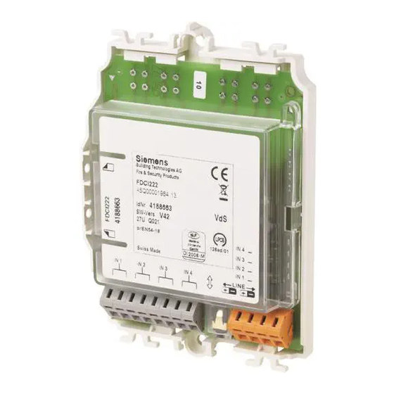
Structure and function Setup 3.2.1 Input module FDCI222 Figure 3: Overview FDCI222 1 Cable tie holder 4 Connection for MC-Link 2 Holes for securing the module 5 Terminal (inputs) 3 Terminal (FDnet/C-NET) 6 Holes for mounting feet FDCM291 18 | 50... -
Page 19: Input/Output Modules Fdcio222 And Fdcio224
Structure and function Setup 3.2.2 Input/output modules FDCIO222 and FDCIO224 Figure 4: Overview of FDCIO222 and FDCIO224 1 Cable tie holder 5 Connection for MC-Link 2 Terminal (outputs) 6 Terminal (inputs) 3 Holes for securing the module 7 Holes for mounting feet FDCM291 4 Terminal (FDnet/C-NET) 19 | 50 007023_k_en_--... -
Page 20: Printed Circuit Board View
Structure and function Setup 3.2.3 Printed circuit board view Figure 5: Printed circuit board view 1 Terminals for output OUT D (only for FDCIO22x) 2 Terminals for output OUT C (only for FDCIO22x) 3 Terminals for output OUT B (only for FDCIO22x) 4 Terminals for output OUT A (only for FDCIO22x) 5 LED for indicating the status of output OUT D (only for FDCIO22x) 6 LED for indicating the status of output OUT C (only for FDCIO22x) -
Page 21: Leds
Structure and function Setup 3.2.4 LEDs The tables below show the meaning of the LED states. Operating LED Status LED Meaning Green LED flashes every 4 sec. Normal operation Green LED flashes every 1 sec Localization mode Yellow LED is flashing Fault Test mode Yellow and green LEDs are... -
Page 22: Function
IN 3 OUT C IN 3 IC-3 OUT D OC-D IN 4 OUT D IC-4 IN 4 FDCI222 FDCIO222, FDCIO224 Figure 6: Block diagram for modules Designation Legend Comment IN 1 ... IN 4 Inputs OUT A ... OUT D Outputs... -
Page 23: Inputs
Structure and function Function 3.3.2 Inputs 3.3.2.1 Configuration options The inputs can be used to monitor the status, e.g. whether a 'door is closed'. Each input can be configured as follows: Status input or danger input Lead monitoring for 'Open line' or 'Open line and short circuit' The input is active when the contact is open (normally closed, NC) The input is active when the contact is closed (normally open, NO) Filter time (0...240 s) -
Page 24: Circuit
FDCI222/FDCIO222 Rs 1.15 k Figure 7: FDCI222 and FDCIO222 circuitry The FDCI222/FDCIO222 connection diagram applies to monitoring for short- circuit and open line. When the line is only to be monitored for open line, the resistor Rs 1.15 k must not be provided. -
Page 25: Outputs (Only With Fdcio222/Fdcio224)
Structure and function Function 3.3.3 Outputs (only with FDCIO222/FDCIO224) This section describes the function mode when controls are not monitored. The chapter 'Monitoring the control with the inputs (only with FDCIO222/FDCIO224) 26]' describes how the controls are monitored by the inputs. Control functions can be performed with the outputs (e.g. -
Page 26: Monitoring The Control With The Inputs (Only With Fdcio222/Fdcio224)
Structure and function Function 3.3.4 Monitoring the control with the inputs (only with FDCIO222/FDCIO224) General With the input/output modules the effected control functions (e.g. 'close door') can be monitored for correct execution (e.g. 'door closed') (see graphics). FDCIO222, FDCIO224 OUT A OC-A IN 1 µP... -
Page 27: Line Separator
Structure and function Function Allocation of inputs and outputs The assignment of outputs to inputs is fixed. Input Output IN 1 OUT A IN 2 OUT B IN 3 OUT C IN 4 OUT D 3.3.5 Line separator All FDnet/C-NET devices are equipped with a line separator. The FDnet/C-NET device is equipped with electronic switches which isolate the defective part in case of a short-circuit on the FDnet/C-NET detector line. -
Page 28: Diagnosis Levels
Structure and function Function 3.3.6 Diagnosis levels The devices largely monitor their function autonomously. The following diagnosis levels are derived from the different control measurements: Normal Fault For details, see table below. When an error occurs which impairs the correct functionality of the module, a module fault message is reported. -
Page 29: Behavior In Degraded Mode
Structure and function Accessories 3.3.7 Behavior in degraded mode Applicable for the FDnet/C-NET: When the main processor of the fire control panel fails, the control panel works in degraded mode operation. Depending on the control panel type, the fire control panel can continue to perform the most important alarming and signaling functions in degraded mode operation. -
Page 30: Housing Fdch221
Structure and function Accessories 3.4.2 Housing FDCH221 To protect against dust and wetness Compatible with: – Multi line separator module FDCL221-M – Input module FDCI22x(-CN) – Input/output module FDCIO22x(-CN) – Output module FCA1209-Z1 – Radio gateway FDCW241 – Zone module, external powered FDCI223, FDCI723 –... -
Page 31: M20 X 1.5 Metal Counter Nut
Structure and function Accessories 3.4.5 M20 x 1.5 metal counter nut For use with metal cable gland M20 x 1.5 Order number: A5Q00004479 3.4.6 Cable ties 2.4 x 137 For strain relief on the connection wires or generally for attachment Made from polyamide Compatible with: –... -
Page 32: Planning
Planning Compatibility 4 Planning When planning a project, proceed as follows: 1. Take into account the compatibility. 2. Define the place of installation. 3. Define the type of monitoring and configuration of the inputs. 4. Define the configuration of the outputs. 5. -
Page 33: Defining The Place Of Installation
Planning Defining the place of installation 4.2 Defining the place of installation Installation specification for controlling fire protection installations For the purpose of controlling fire protection installations in accordance with EN 54- 2, the input/output module FDCIO221 must be integrated into the fire control housing. -
Page 34: Defining The Type Of Monitoring And Input Configuration
Planning Defining the type of monitoring and input configuration 4.3 Defining the type of monitoring and input configuration There must be no automatic fire detector and no manual call point connected to the inputs. 1. Define the type of input (danger input or status input). 2. -
Page 35: Defining The Output Configuration
Planning Defining the output configuration 4.4 Defining the output configuration WARNING Voltages up to AC 250 V on the terminals of the module! Danger to life through contact with live components! Use the housing FDCH221 if switching voltages >DC 60 V (ripple <10 % of average value) or >AC 30 V (peak value max. -
Page 36: Filling Out The Configuration Sheet
Planning Filling out the configuration sheet 4.5 Filling out the configuration sheet 1. Copy out the configuration sheet. You will find the configuration sheet in the attachment. 2. Fill out the configuration sheet. 3. Hand over copies of the completed configuration sheet to the installer and the service technician. -
Page 37: Mounting / Installation
Mounting / Installation Mounting on a U-rail 5 Mounting / Installation WARNING Voltages up to AC 250 V on the terminals of the module! Danger to life through contact with live components! Use the housing FDCH221 if switching voltages >DC 60 V (ripple <10 % of average value) or >AC 30 V (peak value max. -
Page 38: Mounting In Housing Fdch221
Mounting / Installation Mounting in housing FDCH221 5.2 Mounting in housing FDCH221 The module can be installed at any location, along with the separate FDCH221 housing. When installing the module in the housing FDCH221, proceed as follows: 1. Open the housing. 2. -
Page 39: Connecting The Module
Connect module according to diagram in 'Printed circuit board view [ 20]' chapter. LINE LINE + – + – + – + – FDCI222 FDCI222 FDCIO222 FDCIO222 FDCIO224 FDCIO224 – LINE LINE –... -
Page 40: Commissioning
Commissioning 6 Commissioning The devices are commissioned via the control panel. The exact procedure is described in the control panel documentation. Conduct a performance check once commissioning is complete. 40 | 50 Building Technologies 007023_k_en_-- Fire Safety 2017-11-22... -
Page 41: Maintenance / Troubleshooting
Maintenance / Troubleshooting Performance check 7 Maintenance / Troubleshooting 7.1 Performance check The devices are automatically subjected to a performance check during the self- test. Nevertheless, it is necessary to check the devices on site at regular intervals. Recommendation: Check the devices every year. Replace heavily soiled or damaged devices. -
Page 42: Specifications
You will find information on approvals, CE marking, and the relevant EU directives for this device (these devices) in the following document(s); see 'Applicable documents' chapter: Document 007024 Detector line Operating voltage DC 12…33 V Operating current (quiescent): FDCI222 0.25…0.35 mA FDCIO222/FDCIO224 0.6…0.75 mA Maximum current/quiescent current connection factor: FDCI222 FDCIO222/FDCIO224... - Page 43 Inputs Monitoring voltage 3 V, unloaded Monitoring resistors parallel Rp / serial Rs: FDCI222/FDCIO222 3.01 k / 1.15 k ; each +/-1 %; 0.25 W FDCIO224 2.7 k / 560 ; each +/-1 %; 0.25 W 3.3 k / 680 ; each +/-1 %; 0.25 W Line resistance Max.
- Page 44 Specifications Technical data Mechanical data Dimensions (L x W x H): Module 132 x 90 x 21 mm Housing FDCH221 207 x 119 x 50 mm Housing material Color: Module carrier ~RAL 9010, pure white Housing cover Transparent matt Housing FDCH221 ~RAL 9010, pure white Standards European standards...
-
Page 45: Dimensions
Specifications Dimensions 8.2 Dimensions Input module FDCI222 Input/output module FDCIO222, FDCIO224 43.5 46.5 Housing FDCH221 All dimensions in mm 45 | 50 007023_k_en_-- Building Technologies Fire Safety 2017-11-22... -
Page 46: Environmental Compatibility And Disposal
Specifications Environmental compatibility and disposal 8.3 Environmental compatibility and disposal This equipment is manufactured using materials and procedures which comply with current environmental protection standards as best as possible. More specifically, the following measures have been undertaken: Use of reusable materials Use of halogen-free plastics Electronic parts and synthetic materials can be separated Larger plastic parts are labeled according to ISO 11469 and ISO 1043. -
Page 47: Annex
Annex Configuration sheet 9 Annex 9.1 Configuration sheet Mounting site Module Input module FDCI222 Input/output module FDCIO222 Input/output module FDCIO224 Mode of mounting Without housing With housing FDCH221 Input IN 1 monitored ... Input IN 2 monitored ... Input IN 3 monitored ... -
Page 48: Index
Index / Index Impact Application area Chemicals............36 Ambient conditions ......... 36 Moisture ............36 Approvals ............42 Temperature ........... 36 Auxiliary supply ..........22 Intelligent detector tester Diagnosis levels ..........28 CE marking ............. 42 Intelligent detector tester FDUD293 Collective behavior MC link ............ - Page 49 Index / Standards ............44 VdS extinguishing interface Status input ............ 23 Connection ............. 24 FDCIO224 ............15 Type plate Installation specification ........33 Product version ..........17 49 | 50 007023_k_en_-- Building Technologies Fire Safety 2017-11-22...
- Page 50 Issued by © Siemens Switzerland Ltd, 2004 Siemens Switzerland Ltd Technical specifications and availability subject to change without notice. Building Technologies Division International Headquarters Theilerstrasse 1a CH-6300 Zug +41 58 724 2424 www.siemens.com/buildingtechnologies Document ID: 007023_k_en_-- Manual FD20 / FD720...