
Related Manuals for JRC JUE-95LT


Summary of Contents for JRC JUE-95LT
- Page 1 JUE-95LT JUE-95LT INMARSAT mini-C INMARSAT mini-C MOBILE EARTH STATION MOBILE EARTH STATION INSTRUCTION INSTRUCTION MANUAL MANUAL...
- Page 3 PREFACE Thank you for purchase of the JRC Inmarsat mini-C, Mobile Earth Station, JUE-95LT. JUE-95LT has been developed for LRIT (Long Range Identification and Tracking). • Please read this manual carefully and carry out proper operation. • Please keep the manual importantly to refer when it is necessary.
- Page 4 ATTENTIONS BEFORE USING • JRC cannot accept responsibility for any loss due to incorrect operation, malfunction, and other causes except product guarantee condition and liability by law. • There is possibility that some functions of the terminal may not operate correctly depend on the hardware and software version of equipment connected to the terminal.
- Page 5 BEFORE OPERATION About safety symbols This manual and the terminal are indicated the following safety symbols for your correct operation to prevent your and somebody’s injury or damage to the product and assets. The symbols and descriptions are as follows. You should understand well them before reading this manual and operating the terminal.
- Page 6 ABOUT WORNING LABELS Below mentioned warning labels are put on JUE-95LT. Do not take off, destroy or modify these labels. Labels put on EME(NAF-742LT) <Type1> <Type2> Labels put on EME(NAF-253LT) <Type1> <Type2>...
- Page 7 Labels put on IME<Type1> (EME:NAF-742LT) Note 1 ( ) Note 2 ( ) <Type2> (EME: NAF-742LT) Labels put on IME<Type1> (EME: NAF-253LT) <Type2> (EME: NAF-253LT) Notes 1)Attestation number which means safe, high-quality product and suits EU instruction (Free circulation was permitted in the EU signatory). 2) Technological, standard agreement proof and attestation number issued by Telecom Engineering Center Foundation in Japan.
-
Page 8: Caution During Operation
CAUTION DURING OPERATION WARNING Do not bring JUE-95LT (EME) close to the fire, or put it in the fire. It causes the explosion, generation of heat, and the ignition of a built-in lithium battery. Do not approach the JUE-95LT (EME) while transmitting, It transmits microwave and strong microwave might be cause injury. - Page 9 Do not paint radome. Painting of radome may cause decrease of the communication quality. Ask our agency or office to abandon JUE-95LT (EME). When the lithium battery is short-circuited, receives the impact or it gets wet because of water, it causes generation of heat,...
-
Page 10: Abbreviations
ABBREVIATIONS Externally Mounted Equipment EXT PSU Externally Power supply Unit Internally Mounted Equipment INMARSAT INMARSAT Ltd. Mobile Earth station LRIT Long Range Identification and Tracking viii... -
Page 11: Table Of Contents
1-2-2 LRIT mounting requirement schedule ..................1-2 1-3 LRIT operation ..........................1-3 CHAPTER 2. COMPOSITION ......................2-1 2-1 JUE-95LT Installation cable connection system diagram and components list ......2-1 2-2 JUE-95LT Standard components Appearance ................2-3 2-2-1 EME (NAF-742LT/NAF-253LT) ..................... 2-3 2-2-2 IME (NTF-782LT) ........................ - Page 12 4-7-1 About the longevity of the articles of consumption (exchange time) ........4-11 4-7-2 When ordering repair ......................4-11 4-7-3 Recommendation of overhaul ....................4-12 4-7-4 Disposal ..........................4-12 CHAPTER 5. SPECIFICATION ......................5-1 5-1 JUE-95LT ............................. 5-1 CHAPTER 6. JRC Service Network ...................... 6-1...
-
Page 13: Chapter 1. Lrit
CHAPTER 1. LRIT 1-1 LRIT system overview 1-1-1 What is LRIT system? Long-Range Identification and Tracking (LRIT) is the global monitoring system of ship's movement. (1) LRIT system is obligation facilities of IMO. (2) It is a system that transmits peculiar information of the ship (ship's communication ID and position information) from Inmarsat-C terminals or other communication equipments, by the commands from land. -
Page 14: Lrit
1.2 LRIT 1-2-1 LRIT mounting requirements By addition of MSC.202(81) SOLAS V 19-1 1-2-1-1 Object ships: International navigation ships Passenger ships(including high-speed passenger ships), cargo ships (including high-speed craft), and mobile offshore drilling units. 1-2-1-2 SOLAS V, 19-1 rule of LRIT(mounting requirements are added) (1)A ship which built after 31 December 2008 (excluding sea area A1 limited navigation ship). -
Page 15: Lrit Operation
1-2-3 Functional requirements of LRIT terminal By addition of MSC.242(83), MSC.263(84), SOLAS V 19-1 (1) It can be sent LRIT information with 6 hours intervals automatically. (2) It can be control the sending intervals (15 minutes to 6 hours) by remote control from the land. (3) It can be sent LRIT information by polling. -
Page 17: Chapter 2. Composition
CHAPTER 2. COMPOSITION 2-1 JUE-95LT Installation cable connection system diagram and components list 1. Standard (DC24V) Externally Mounted Equipment (EME) NAF-742LT /NAF-253LT Internally Mounted Equipment (IME) NTF-782LT 7ZCSC0202 Power Supply Cable Coaxial Cable CFQ-5924A Ship's Power DC POWER (JRC supply) - Page 18 Table 2-1 JUE-95LT Components list Equipment Type Q’ty JUE-95LT NAF-742LT/NAF-253LT (Standard) NTF-782LT EME-IME Coaxial Cable CFQ-5924A3 (30m) EXT Power Cable 7ZCSC0202 Supplied parts for EME installation MPXP33400 Supplied parts for IME installation MPXP33399 Spare parts for Installation by JRC 7ZXSC8501...
-
Page 19: Jue-95Lt Standard Components Appearance
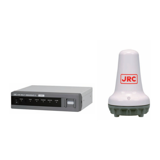
2-2 JUE-95LT Standard components Appearance 2-2-1 EME (NAF-742LT/NAF-253LT) The EME is installed above deck for receiving signals from satellites. The EME is covered with a radome. Fig.2-2-1a EME (NAF-742LT) Fig.2-2-1b EME (NAF-253LT) -
Page 20: Ime (Ntf-782Lt)
2-2-2 IME (NTF-782LT) The IME is installed below deck. (9)DIMMER button (8)RESET button (7)ALARM lamp (6)RECEIVE lamp (5)TRANSMIT lamp (4)LOG-IN lamp (3)SYNC lamp (2)POWER lamp (1)POWER switch Fig. 2-2-2a IME Front view (1)EME connecter (4)Connecter for optional equipment (2)PSU connecter (3)DTE connecter Fig. -
Page 21: Coaxial Cable (Cfq-5924A3)
2-2-3 Coaxial cable (CFQ-5924A3) Fig. 2-2-3 Coaxial Cable... -
Page 22: Optional Components Appearance
2-3 Optional components appearance 2-3-1 EXT PSU (NBD-577C) Fig. 2-3-1 EXT PSU (NBD-577C) 2-3-2 EXT PSU (NBD-843A) Fig. 2-3-2 EXT PSU (NBD-843A) - Page 23 Coaxial Cable(CFQ-5922A5) Fig.9 Coaxial Cable(CFQ-5922A5) Fig. 2-3-3 Coaxial Cable(CFQ-5922A5)...
-
Page 24: Configuration (Jue-95Lt) Dimensional Drawing
2-4 Configuration (JUE-95LT) Dimensional drawing 2-4-1 EME (NAF-742LT) Unit: mm Mass: Approx. 1.5kg Fig. 2-4-1 EME(NAF-742LT) -
Page 25: Eme (Naf-253Lt)
2-4-2 EME (NAF-253LT) Unit: mm Mass: Approx. 2.4 kg Color: N9 Fig. 2-4-2 EME(NAF-253LT) -
Page 26: Ime (Ntf-782Lt)
2-4-3 IME (NTF-782LT) Unit: mm Fig. 2-4-3 IME Mass: Approx. 1.3kg 2-10... -
Page 27: Coaxial Cable (Cfq-5924A3)
2-4-4 Coaxial cable (CFQ-5924A3) Unit: mm Type Length Mass CFQ-5924A3 Approx.2.3kg 30m±1.0m Minimum bending radius:46mm Fig. 2-4-4 Coaxial cable 2-11... -
Page 28: Optional Equipment Dimensional Drawing
2-5 Optional Equipment Dimensional drawing 2-5-1 EXT PSU (NBD-577C) Specification Input voltage: AC 100/220V (typical), ±10% 50/60Hz (typical), Single phase DC 24V (typical), +30%, -20% Output voltage: DC 24V Caution Before installation, do the following procedure. 1. Set the plug “P1” to suitable receptacle according to the input voltage. -
Page 29: Ext Psu (Nbd-843A)
2-5-2 EXT PSU (NBD-843A) Unit: mm Mass: Approx. 8kg Fig. 2-5-2 EXT PSU (NBD-843A) 2-13... -
Page 31: Chapter 3. Operation
CHAPTER 3. OPERATION Before turning on all power switches of JUE-95LT, confirm all the signal cables and power cables are connected correctly. Regarding the details of LED lamp display, switch functions, and connecting cable and connector, refer table 3-1 to 3-3 in next page. - Page 32 Remarks (1) POWER switch Power ON/OFF the MES. (8) RESET button To reset the status of JUE-95LT when it Refer to chapter 4-6 of this manual and operates abnormally. be careful to handle this button. (It seems to a very little hole.
-
Page 33: Chapter 4. Maintenance
The following table shows daily maintenance items using general tools. WARNING Do not check or repair the internal equipment of JUE-95LT by yourself. Any electrical work by any person other than our specialized maintenance persons may cause fire or abnormal operation of this equipment or electrical shock for you. -
Page 34: Troubleshooting Flow Chart
Check all items in the following section to secure normal communication at all times. If any unusual phenomenon occurs in the equipment, send appropriate information to JRC service network to get advice or to request for repair with the results of these items. - Page 35 From previous page Is LOG-IN lamp lit Is ID registered? after 2 minutes ? Application Does Buzzer Replacement sounds during operation? (EME internal GPS error) ALM lamp Countermeasure Alarm/Error status contents ・Light is disappeared Blinking with 0.5 after rebooting seconds intervals Power source: ALM Lamp Normal return...
-
Page 36: Shadow-Sector Countermeasure
4-4 Shadow-sector countermeasure 4-4-1 Fore and aft directions Shadow-sector is generated when Setup without obstacle down to -5°. some obstacle is exist in slashed part. -5° 4-4-2 Port and starboard directions Setup without obstacle down to -15°. Shadow-sector is generated when some obstacle is exist in slash part. -
Page 37: Reference: Estimation Methods Of Rx/Tx Signal Loss By Physical Obstructions
4-4-4 Reference: Estimation methods of RX/TX signal loss by physical obstructions Attenuation with the obstacle calculates easily in the following method. I. Estimation procedure with the chart 4-4-4a (for cylindrical obstacles) i) Estimate the distance (R) from the obstacle; R (m) d=0.2m ii) Estimate the effective diameter (d) of the obstacle;... - Page 38 II. Estimation procedure with the chart 4-4-4b ( by GMDSS Performance Standards) d (m) Obstacle 2° d (m) R (m) It adapts to GMDSS Performance distance, if the distance between an obstacle and EME has enough distance Diameter GMDSS Performance standards of an non-adaptive installation distance obstacle...
- Page 39 III. Estimation procedure with the chart ( for un-cylindrical obstacles) i) Estimate the distance (R) from the antenna to the obstacle R (m) ii) Read the effective propagation radius (r) at R meter distance (at point A) from the antenna in the Chart 4-4-4c r (m) iii) Estimate the obstacle area (S ) just occupying effective propagation...
- Page 40 Chart 2.3.5d The loss due to un-cylindrical obstacle Fig.4-4-4d The loss due to un-cylindrical obstacles NOTE *When the satellite is existed under lower elevation angle area, sometimes the communication might be impossible due to fading or weather condition.
-
Page 41: Noise Countermeasure (Interference With Other Equipment)
4-5 Noise countermeasure (Interference with other equipment) Earthing of EME antenna is highly recommended when trouble is caused in transmission (noise interference, e.t.c.) due to occurrence of interference with other communication device. Earth bolt MTL318538A (Option) Fig. 4-5 Earthing of EME antenna... -
Page 42: Countermeasure
RECEIVE approximately 10 seconds). Turn on POWER switch with confirming these lamps are blinking. JUE-95LT may not reboot due to short-circuit of RESET button, if this button is pressed so strongly. NOTE The data, which are received message, call logging history and alarm history, memorized in IME are cleared when RESET button is pushed. -
Page 43: After Service
However, in the following case, gratis service cannot be received even if it is during the term of a guarantee. -When the construction report is not sent to JRC after installation of JUE-95LT is completed. -Failure produced by inevitability, such as misuse, negligence, or a natural disaster, a fire, etc. -
Page 44: Recommendation Of Overhaul
4-7-4 Disposal When disposing packaging materials of JUE-95LT, follow the rules of the pertinent local government. CAUTION Contact JRC to abandon JUE-95LT (EME). When the lithium battery is short-circuited, receives the impact or it gets wet because of water, it causes generation of heat, the explosion, and the ignition if this is not defended. -
Page 45: Chapter 5. Specification
CHAPTER 5. SPECIFICATION 5-1 JUE-95LT Table 5-1 Principal Specification of JUE-95LT Class of Inmarsat-C MES Class 1 Frequency range Transmission 1626.5-1646.5 MHz 1530.0-1545.0 MHz (EME: NAF-742LT) Reception 1537.0-1544.2 MHz (EME: NAF-253LT) Channel spacing 5 kHz EIRP Within +7 - +16 dBW (at 5 degrees elevation angle) -23.7 dB/K minimum... -
Page 47: Chapter 6. Jrc Service Network
CHAPTER 6. JRC Service Network Please contact the dealer from which you purchased the device or our marketing offices that is nearest to you for any question as to the after-sales service. JRC web site JRC Tokyo Japan http://www.jrc.co.jp JRC Amsterdam http://www.jrceurope.com/... - Page 50 For further information,contact: Not use the asbestos http://www.jrc.co.jp Marine Service Department +81-3-3492-1305 Telephone : Facsimile : +81-3-3779-1420 e-mail : tmsc@jrc.co.jp AMSTERDAM Branch Telephone : +31-20-658-0750 Facsimile : +31-20-658-0755 e-mail : service@jrceurope.com SEATTLE Branch Telephone : +1-206-654-5644 Facsimile : +1-206-654-7030 e-mail : marineservice@jrcamerica.com...