
Related Manuals for Red-D-Arc E300 3+2


Summary of Contents for Red-D-Arc E300 3+2
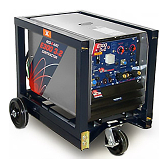
- Page 1 E300 3+2 Electric Welder Service Manual Stick/Mig Capability Welding Excellence Modular Construction Environment Protected 2,000 Watt AC Power for Tools SVM_E300 3+2...
- Page 2 SAFETY Arc Welding Safety Precautions PROTECT YOURSELF AND OTHERS FROM POSSIBLE SERIOUS INJURY OR DEATH. READ AND UNDERSTAND BOTH THE SPECIFIC INFORMATION GIVEN IN THE OPERATING MANUAL FOR THE WELDER AND/OR OTHER EQUIPMENT TO BE USED AS WELL AS THE FOLLOWING GENERAL INFORMATION. 1.
- Page 3 SAFETY AWS F4.1-80 from the American Welding Society. Highway, Arlington, VA 22202. Vent hollow castings or containers before heating, cutting or 8. For Electrically Powered Equipment. welding. They may explode. Turn off input power using the disconnect switch at the fuse box before working on the equipment.
-
Page 4: Operation
OPERATION OPERATION RATED OUTPUT For best operating characteristics and longest unit life, take care in Amperes selecting an installation site. Avoid locations exposed to high Volts humidity, dust, high ambient temperature or corrosive fumes. Make Duty cycle sure that the ventilator openings are not obstructed. •... -
Page 5: Auxiliary Power
This control provides more arc force and eliminates the tendency of snuffing out the arc. AUXILIARY POWER Your E300 3+2 is equipped with AC auxiliary power. The AC unit provides a Duplex 120Volt receptacle and 2KW of maximum output. The output circuit is protected with circuit breakers. -
Page 6: Control Panel
CONTROL PANEL CONTROL PANEL FEATURES FRONT REAR 21 - Voltage change cover 22 - Supply cable input 23 - Grounding screw 1 - On/Off Switch/Breaker 30 AMP 2 - Ground fault protector 3 - On light 4 - Stick/Tig mode select switch (optional) 5 - Remote current switch: Switch must be "off"... -
Page 7: Troubleshooting
Always use the greatest care when working near moving parts. • Do not put your hands near the engine fan. If a problem cannot be corrected by following the instructions, take the machine-to the nearest Red-D-Arc Location. TROUBLE CAUSE WHAT TO DO 1. -
Page 8: Miscellaneous Assembly
ASSEMBLY MISCELLANEOUS ASSEMBLY (SERIAL #s 0880 AND ABOVE) - Page 9 ASSEMBLY MISC. ASSEMBLY PARTS LIST (SERIAL #s 0880 AND ABOVE) ITEM PART NAME & DESCRIPTION NO. REQ'D PART NO. Transformer assembly 15.077 Over load Thermostat 132 degrees C 14.277 Transformer Support 14.886 Insulator 11.707 Terminal Board 17.516 Over load 63 degrees C 14.285 Bracket 16.967...
- Page 10 ASSEMBLY MISC. ASSEMBLY PARTS LIST CONTINUED (SERIAL #s 0880 AND ABOVE) ITEM PART NAME & DESCRIPTION NO. REQ'D PART NO. CC-CV / Tig-Stick mode select switch (Optional lift arc) 13.152 Electronic panel lift arc GS9414 (Optional lift arc) 17.629 Capacitor 40uF 450V 17.094 Tie rod 17.507...
-
Page 11: Wiring Diagrams
WIRING DIAGRAMS PRIMARY WIRING DIAGRAM... -
Page 12: Wiring Diagram
WIRING DIAGRAMS WIRING DIAGRAM... - Page 13 WIRING DIAGRAMS WIRING DIAGRAM WITH OPTIONAL TIG PC BOARD...