Table of Contents
Advertisement
Quick Links
IM10322-B
RED-D-ARC
September 2016
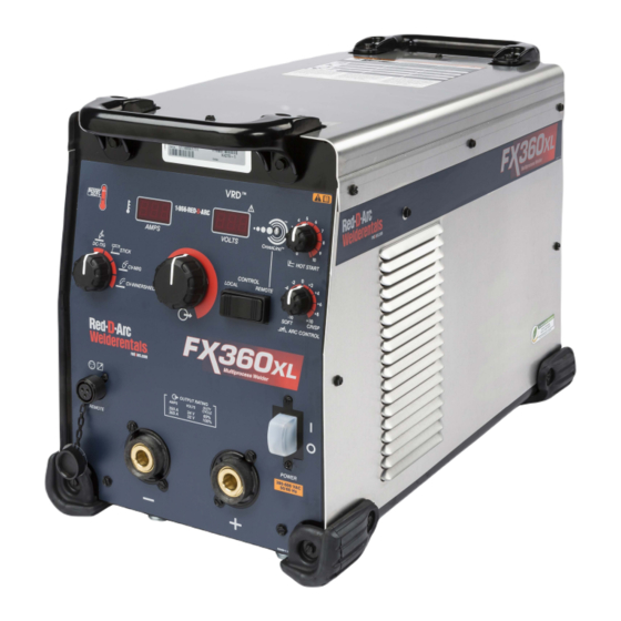
FX360XL
For use with machines having Code Numbers: 12465, 12612, 12577
OPERATOR'S MANUAL
Red-D-Arc Spec-Built Welding Equipment
This RED-D-ARC welder is built to RED-D-ARC Extreme Duty
design specifications by Lincoln Electric.
Safety Depends on You
This welder is designed and built with safety in mind.
However, your overall safety can be increased by proper installation
... and thoughtful operation on your part.
DO NOT INSTALL, OPERATE OR REPAIR THIS EQUIPMENT
WITHOUT READING THIS MANUAL AND THE SAFETY
PRECAUTIONS CONTAINED THROUGHOUT.
And, most importantly, think before you act and be careful.
1-800-245-3660
North America's Largest Fleet of Welding Equipment
Advertisement
Table of Contents

Related Manuals for Red-D-Arc FX360XL


Summary of Contents for Red-D-Arc FX360XL
- Page 1 For use with machines having Code Numbers: 12465, 12612, 12577 OPERATOR’S MANUAL Red-D-Arc Spec-Built Welding Equipment This RED-D-ARC welder is built to RED-D-ARC Extreme Duty design specifications by Lincoln Electric. Safety Depends on You This welder is designed and built with safety in mind.
-
Page 2: Special Situations
THANK YOU FOR SELECTING A QUALITY PRODUCT BY KEEP YOUR HEAD OUT OF THE FUMES. DON’T get too close to the arc. LINCOLN ELEC TRIC. Use corrective lenses if necessary to stay a reasonable distance away from the arc. READ and obey the Material PLEASE EXAMINE CARTON AND EQUIPMENT FOR Safety Data Sheet (MSDS) and DAMAGE IMMEDIATELY... -
Page 3: Section A: Warnings
SAFETY SECTION A: 1.d. Keep all equipment safety guards, covers and devices in position and in good repair.Keep hands, hair, clothing and tools away from WARNINGS V-belts, gears, fans and all other moving parts when starting, operating or repairing equipment. CALIFORNIA PROPOSITION 65 WARNINGS Diesel Engines 1.e. -
Page 4: Electric Shock Can Kill
SAFETY ELECTRIC SHOCK ARC RAYS CAN BURN. CAN KILL. 3.a. The electrode and work (or ground) circuits are 4.a. Use a shield with the proper filter and cover plates to protect your electrically “hot” when the welder is on. Do eyes from sparks and the rays of the arc when welding or not touch these “hot”... - Page 5 SAFETY WELDING AND CUTTING CYLINDER MAY EXPLODE IF SPARKS CAN CAUSE DAMAGED. FIRE OR EXPLOSION. 7.a. Use only compressed gas cylinders containing the correct shielding gas for the process used 6.a. Remove fire hazards from the welding area. If and properly operating regulators designed for this is not possible, cover them to prevent the welding sparks the gas and pressure used.
-
Page 6: Electromagnetic Compatibility (Emc)
SAFETY ELECTROMAGNETIC COMPATIBILITY (EMC) Conformance Products displaying the CE mark are in conformity with European Community Council Directive of 15 Dec 2004 on the approximation of the laws of the Member States relating to electromagnetic compatibility, 2004/108/EC. It was manufactured in conformity with a national standard that implements a harmonized standard: EN 60974-10 Electromagnetic Compatibility (EMC) Product Standard for Arc Welding Equipment. -
Page 7: Welding Cables
SAFETY The size of the surrounding area to be considered will depend on the structure of the building and other activities that are taking place. The surrounding area may extend beyond the boundaries of the premises. Methods of Reducing Emissions Public Supply System Welding equipment should be connected to the public supply system according to the manufacturer’s recommendations. - Page 8 FX360XL TABLE OF CONTENTS...
-
Page 9: General Description
5 to 425 Amp output range. The machine is capable of welding in CC and CV modes with common wire types COMMON COMMON and sizes. The FX360XL is capable of gouging in either Stick or CV WELD MODE PROCESS MATERIALS ELECTRODES modes. -
Page 10: Design Features
FX360XL GENERAL DESCRIPTION DesIGn FeaTUres • Multiple process DC output range: 5 - 425 Amps • Thermostatically protected with Thermal Light. • Simple and Easy to Use • Flexible Multi-Process Capability – Including stick, TIG, MIG, Flux-cored and CAG. •... -
Page 11: Technical Specifications
FX360XL GENERAL DESCRIPTION TeCHnICal speCIFICaTIOns - K4275-1 FX360XL RED-D-ARC POWER SOURCES - INPUT VOLTAGE AND CURRENT INPUT VOLTAGE ± INPUT PRODUCT # DUTY CYCLE IDLE AMPS POWER FACTOR AMPERES K4275-1 60% RATING 380/460/575 3PH 24/22/22 .13/.16/.27 .87/.77/.62 POWER SOURCES - RECOMMENDED INPUT WIRE AND FUSE SIZES1... -
Page 12: Installation
INSTALLATION INSTALLATION Environmental limitations The FX360XL is IP23 rated for use in an outdoor environment. The machine should not be subjected to falling water during use nor should any parts of it be submerged in water. Doing so may cause WARNING improper operation as well as pose a safety hazard. -
Page 13: Case Front Control
10. Weld Process Selector Switch: A rotary switch that toggles machine cools down. When cool, the light goes out and output is enabled. through the 5 available weld modes for the FX360XL – 2. Amperage LCD Display CC-SMAW; CC-GTAW; CV; CV-Innershield. -
Page 14: Case Back Controls
FX360XL INSTALLATION FIGURE A.2 Case BaCk COnTrOls 1. Control Circuit Breaker • 20 amps on all models... - Page 15 FX360XL INSTALLATION FIGURE A.3 - DIP SWITCH LOCATION ON USER INTERFACE PCB...
- Page 16 FX360XL INSTALLATION analOG WIre FeeDer COnneCTIvITy Picture Function Wiring 75 REMOTE POTENTIOMETER, COMMON 3-PIN 76 REMOTE POTENTIOMETER, WIPER CONNECTOR 77 REMOTER POTENTIOMETER, POSITIVE...
-
Page 17: Recommended Electrode And Work Cable Sizes For Arc Welding
Connect the electrode and work cables between the appropriate weld circuit. output studs of the FX360XL per the following guidelines: • Always weld in a direction away from the work (ground) • Most welding applications run with the electrode being connection. - Page 18 FX360XL INSTALLATION parallelInG MaCHInes The FX360XL power sources may be paralleled for increased output requirements in constant current application. No kit is required for paralleling of FX360XL power sources. The FX360XL can only be paralleled for constant current processes. Connect the power sources as shown, and set the output control of each power sources to one half of the desired arc current.
-
Page 19: Control Setting
FX360XL INSTALLATION COnneCTInG ln-15(k1870-1) TO THe reD-D-arC FX360lX WIRE FEEDER LN-15 RED-D-ARC FX360LX ELECTRODE (K1870-1) WORK CLIP WORK CONTROL SETTING WELD MODE CV, CV-INNERSHIELD WELD TERMINALS REMOTE/LOCAL LOCAL VOLTMETER POLARITY PROCESS DEPENDENT... - Page 20 FX360XL INSTALLATION COnneCTInG aCTIv8, ln-25 prO serIes, ln-25 pIpe, ln-25 IrOnWOrker anD ln-25X TO THe reD-D-arC FX360lX WIRE FEEDER LN-25 PRO LN-25 Pipe LN-25 Ironworker RED-D-ARC FX350LX ELECTRODE LN-25x WORK CLIP WORK CONTROL SETTING WELD MODE CV, CV-INNERSHIELD WELD TERMINALS...
-
Page 21: Operation
Wear eye, ear and body protection. INPUT VOLTAGE SEE ADDITIONAL WARNING INFORMATION UNDER “ARC WELDING SAFETY PRECAUTIONS” ON INSIDE OF FRONT COVER OF OPERATING MANUAL. OUTPUT VOLTAGE GRAPHIC SYMBOLS THAT APPEAR ON THE FX360XL OR IN THIS MANUAL INPUT CURRENT INPUT POWER OUTPUT CURRENT PROTECTIVE... -
Page 22: Power-Up Sequence
DUTy CyCle voltage) weld mode used for welding the GMAW mig welding ® The FX360XL is capable of welding at a 100% duty cycle INNERSHIELD process and the FCAW-GS, flux (continuous welding) at 300 Amps rated output. cored gas shielded welding process. -
Page 23: Weld Controls And Displays
FX360XL OPERATION Volt Display Meter DeFInITIOn OF WelDInG MODes • Prior to CV operation (current flow), the meter displays desired preset voltage NON-SYNERGIC WELDING MODES value (+/- .1V). • A Non-synergic welding mode requires all welding process • Prior to STICK or TIG operation, the meter variables to be set by the operator. - Page 24 VRD Lights There are two indicator lights on the case front of the FX360XL above the Voltage display to indicate the status of VRD operation. As shipped, the VRD function is disabled. VRD is enabled by setting dip switch number 5 to the on position on the User Interface P.C.
-
Page 25: Basic Modes Of Operation
12-pin or 14-pin BasIC MODes OF OperaTIOn connectors), the output is controlled through the Output Control dial on the front of the Red-D-Arc FX360LX. Set this switch to ‘Remote’ when an external potentiometer/control is connected. GTAW... - Page 26 FX360XL OPERATION SMAW This weld mode is a constant current (CC) mode featuring continuous control from 15 – 425 Amps. It is intended for the SMAW stick welding processes and arc gouging. The mode can also be used for TIG operation without changing modes.
- Page 27 Output Control This weld mode is a constant voltage (CV) mode featuring dial on the front of the Red-D-Arc FX360LX. Set this switch to continuous control from 10 to 45 volts. ‘Remote’ when an external potentiometer/control is connected or It is intended for the FCAW-SS welding process and arc gouging.
- Page 28 CrossLinc™ - CrossLinc is a new welding system communication technology. When using a CrossLinc enabled power source such as the FX360XL and a CrossLinc enabled wire feeder such as the LN-25X, welding voltage can be controlled remotely without the use of an additional control cable.
-
Page 29: Optional Kits And Accessories
FX360XL ACCESSORIES OPTIONAL KITS AND ACCESSORIES K3059-4 Inverter and Wire Feeder Cart.* Rear-wheeled cart with front casters and gas bottle platform. Convenient handles allow for easy cable storage. Small footprint fits through 30 in. (762 mm) door. Not intended for use with double head wire feeders. -
Page 30: Maintenance
Before carrying out service, maintenance and/or minimum. repair jobs, fully disconnect power to the machine. 4. Turn on the Red-D-Arc FX360LX. Use Personal Protective Equipment (PPE), including 5. The display should read “Cur CAL”. safety glasses, dust mask and gloves to avoid injury. - Page 31 2. Put dipswitch 1 in the on position. 3. Rotate the Hot Start knob and Arc Control knob to the minimum. 4. Turn on the Red-D-Arc FX360LX. 5. The display should read “Cur CAL”. 6. Rotate the Arc Control knob until the display reads “Fct Cur”.
-
Page 32: Troubleshooting
FX360XL TROUBLESHOOTING TROUBLESHOOTING WARNING Service and Repair should only be performed by Lincoln Electric Factory Trained Personnel. Unauthorized repairs performed on this equipment may result in danger to the technician and machine operator and will invalidate your factory warranty. For your safety and to avoid Electrical Shock, please observe all safety notes and precautions detailed throughout this manual. - Page 33 FX360XL TROUBLESHOOTING Observe all Safety Guidelines detailed throughout this manual PROBLEM POSSIBLE CAUSE RECOMMENDED COURSE OF ACTION Major physical or electrical 1. Contact your local authorized Lincoln Electric damage is evident when the Field Service facility for technical assistance. sheet metal covers are removed.
-
Page 34: System Problems
FX360XL TROUBLESHOOTING Observe all Safety Guidelines detailed throughout this manual The status lights on the User Interface board, Crosslinc™, Input UsInG THe sTaTUs leD TO TrOUBlesHOOT sysTeM prOBleMs board, Control board and the Switch board are dual-color LED’s or green LEDs. Normal operation for each is described on the wiring Errors are displayed on the user interface. - Page 35 FX360XL TROUBLESHOOTING ERROR DESCRIPTION POSSIBLE CAUSE CORRECTIVE ACTION CODE# DC Link Capacitor Over/Under The voltage on the main DC link Verify all three phases of the AC input are connected Voltage capacitors housed on the switchboard has either gone too high or too low If for any reason you do not understand the test procedures or are unable to perform the tests/repairs safely, contact your Lincoln Authorized Service Facility for technical troubleshooting assistance before you proceed.
- Page 36 FX360XL DIAGRAMS WIrInG DIaGraM - CODe 12465, 12612...
- Page 37 FX360XL DIAGRAMS WIrInG DIaGraM - CODe 12577...
- Page 38 FX360XL DIAGRAMS DIMensIOnal prInT 25.70 13.32 22.92 16.59...
- Page 39 WARNING Do not touch electrically live parts or Keep flammable materials away. Wear eye, ear and body protection. electrode with skin or wet clothing. Insulate yourself from work and AVISO DE ground. Spanish PRECAUCION No toque las partes o los electrodos Mantenga el material combustible Protéjase los ojos, los oídos y el bajo carga con la piel o ropa moja-...
- Page 40 WARNING Keep your head out of fumes. Turn power off before servicing. Do not operate with panel open or Use ventilation or exhaust to guards off. remove fumes from breathing zone. AVISO DE Spanish PRECAUCION Los humos fuera de la zona de res- Desconectar el cable de ali- No operar con panel abierto o piración.
- Page 41 CUSTOMER ASSISTANCE POLICY The business of The Lincoln Electric Company is manufacturing and selling high quality welding equipment, consumables, and cutting equipment. Our challenge is to meet the needs of our customers and to exceed their expectations. On occasion, purchasers may ask Lincoln Electric for advice or information about their use of our products.