Ritron PATRIOT PBS-446D Operating Manual
Uhf fm band programmable base radio
Hide thumbs
Also See for PATRIOT PBS-446D:
- Owner's manual (26 pages) ,
- User manual (20 pages) ,
- Operating instructions manual (17 pages)
Table of Contents
Advertisement
Quick Links
TYPE OF EXHIBIT:
FCC PART:
MANUFACTURER:
MODEL:
TYPE OF UNIT:
FCC ID:
DATE:
Included in this exhibit is a draft of the Maintenance and Operating Manual for the Ritron Patriot Model
PBS-446D UHF-FM Base Transceiver.
Specifically, the manual includes a technical description of the PBS-446D sufficient to establish
compliance with the technical standards of the applicable rule part(s).
This includes, but is not limited to, the following items required under FCC Part 2.1033(c):
(2)
FCC Identifier.
(3)
A copy of the installation and operating instructions.
(4)
Type of emission.
(5)
Frequency range.
(6)
Range of operating power, and means to provide variation in operating power.
(7)
Maximum power rating.
(8)
DC voltage chart.
(9)
Tune-up procedure.
(10) A description of all frequency determining and stabilization circuits. A description of the circuits
used to suppress spurious radiation, limiting modulation, and limiting power.
(12) Drawing with labels for controls and complete circuit diagrams.
Signed:
Michael A. Pickard - Project Engineer
OPERATIONAL DESCRIPTION
2.1033 (c)(6)
RITRON, INC.
505 West Carmel Drive
Carmel, IN 46032
PBS-446D
UHF-FM Base Transceiver
AIERIT16-446
December 9, 2002
Advertisement
Table of Contents

Related Manuals for Ritron PATRIOT PBS-446D


Summary of Contents for Ritron PATRIOT PBS-446D
- Page 1 AIERIT16-446 DATE: December 9, 2002 Included in this exhibit is a draft of the Maintenance and Operating Manual for the Ritron Patriot Model PBS-446D UHF-FM Base Transceiver. Specifically, the manual includes a technical description of the PBS-446D sufficient to establish compliance with the technical standards of the applicable rule part(s).
- Page 2 UHF FM BAND PROGRAMMABLE BASE RADIO MAINTENANCE / REPAIR / OPERATING MANUAL FOR USE BY AUTHORIZED SERVICE/MAINTENANCE PERSONNEL ONLY PBS-446D-MRM REV A COPYRIGHT 2002 RITRON, INC. • ALL RIGHTS RESERVED RITRON, JOBCOM, and QUIET CALL, ARE REGISTERED TRADEMARKS OF RITRON, INC.
-
Page 3: Table Of Contents
TABLE OF CONTENTS PBS-446D TOPIC PAGE TOPIC PAGE IMPORTANT MAINTENANCE/REPAIR INFORMATION .. 1 Programmable Features ..........14 Descriptions of Features..........14 SPECIFICATIONS 2-Tone Paging Options ..........15 Scan Channel Options..........15 GENERAL................. 2 CONTROLS ..............2 THEORY OF OPERATION TRANSMITTER..............3 RECEIVER................ -
Page 4: Important Maintenance/Repair Information
RITRON’s warranty. If you Mouser Corporation is one source, stock number are not completely familiar with surface mounted 382-0004 (2.5mm jack) and 382-0006 (3.5mm jack). -
Page 5: Specifications
“transmit beep”. Environmental: Splash resistant and shock and vibration per Channel: Programmable for a RITRON Drop Test (6 ft. Channel beep whenever drop onto concrete on all the channel is changed. six sides) When the scan channel is Antenna Fitting: selected the radio emits a Scan beep. -
Page 6: Transmitter
SPECIFICATIONS PBS-446D TRANSMITTER BATTERY RF Power Output: 2.5 Watts @ +13 VDC Battery Drain at 12 VDC: Wide Mode Narrow Mode Standby: 71 mA Sleep: 25 mA Emission Designator: 16K0F3E 11K0F3E Avg. Standby Deviation: +/- 5.00 KHz +/- 2.50 KHz with Power Saver: 28.5 mA FM Hum and Noise:... -
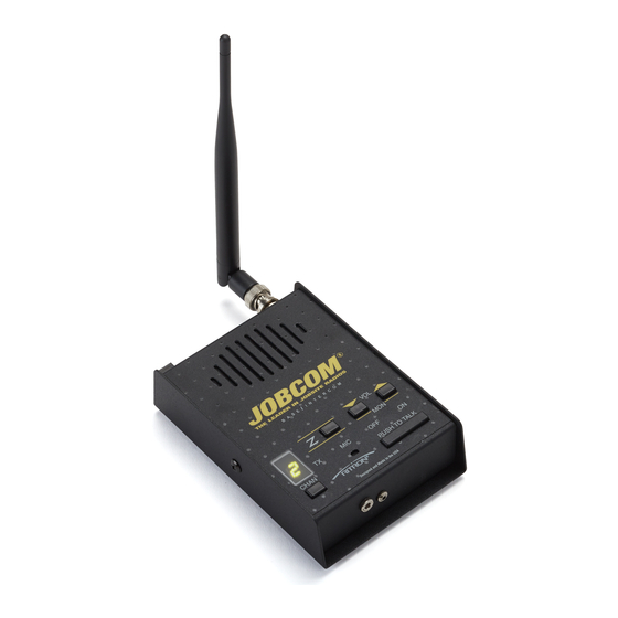
Page 7: Introduction
INTRODUCTION PBS-446D GENERAL EXPOSURE TO RADIO FREQUENCY ENERGY RITRON's PBS-446D base station is a small, The PBS “D-Series” base radios generate programmable two-way radio, designed to operate in electromagnetic energy during transmit mode. This the 450-470 MHz professional FM communications product has been evaluated for compliance with the band. -
Page 8: Operation
OPERATION PBS-446D DESCRIPTION OF CONTROLS AND Power Connector (top end of case) CONNECTORS The power connector on the top end of the radio is used to connect power to the unit, either an external 12 VDC supply or Channel Display the RPS-1A wall-mounted power supply included with the radio. -
Page 9: Basic Radio Operation
Scan radio has been optionally programming for Monitor Beep, then scanning will resume as normal. Lockout. See your Ritron dealer or contact Ritron If the Weather Channel is selected - on a VHF radio directly to disable this option. -
Page 10: Transmit
Priority Channel when scanning. radio except the NOAA Weather Channel. See your Ritron dealer or contact Ritron directly for How Scanning Works PC programming of this option. Using the Channel Selector button, select the Scan Channel. -
Page 11: What The Radio Tones Mean
OPTIONAL RADIO ALERT TONES The PBS "D-Series" base radio can be programmed WHAT THE RADIO ALERT TONES MEAN using the RITRON PC Programmer for optional alert tones. See your Ritron dealer or contact Ritron The radio responds to certain instructions by directly for programming of these options. -
Page 12: Troubleshooting
OPERATION PBS-446D TROUBLESHOOTING Notes If you have trouble operating the base station, review the radio controls and operation sections. If you think the radio is malfunctioning, check the following table. Reception can often be improved by moving a short distance. This effect is more noticeable GENERAL inside of buildings. -
Page 13: Programming The Radio
10 channels. The PBS-446D may be programmed using the Push-to-Talk switch or an 2. Press the Channel Selector button to optional RITRON PC programming kit. select the channel to be read out. The FIELD PROGRAMMING allows you to program any... -
Page 14: How To Field Program Frequency & Tone Codes
PROGRAMMING THE RADIO PBS-446D How to Field Program Frequency & Tone Codes To match other radios, the owner can select 10.Enter the 1 digit of the tone code by Frequency and Tone Codes from Tables 1 and 2 on clicking the PTT button until the page 15. -
Page 15: How To Delete A Channel
PROGRAMMING THE RADIO PBS-446D How to Delete a Channel 14. Turn the radio and then again—the radio is now ready to use. In our example we will delete channel 3. 15. The remaining channels are in the same 1. Follow the instructions in FIG-4 on sequence and will retain their same channel page 12 to place the radio in the number. -
Page 16: Computer Software Copyrights
PROGRAMMING THE RADIO PBS-446D COMPUTER SOFTWARE COPYRIGHTS Code Frequency Description The RITRON, Inc. products described in this manual include copyrighted RITRON, inc. computer 467.7625 programs. Laws in the United States and other 467.8125 countries grant to RITRON, inc. certain exclusive 464.5500... -
Page 17: Programmable Features
PROGRAMMING THE RADIO PBS-446D Programmable Features Descriptions of Features The following features may be programmed on a per Automatic Inactivity Turn-off - The radio automatically channel basis, or will affect all channels together. shuts itself off if four hours go by without the micro- controller detecting input from the volume, PTT or channel controls. -
Page 18: 2-Tone Paging Options
PROGRAMMING THE RADIO PBS-446D PTT Programming Mode Enabled - This feature 2-Tone Squelch When Selected - The radio can be allows channel programming from a table of pre- automatically set for 2-tone paging decode whenever determined frequencies using the radio PTT switch. the channel is selected. -
Page 19: Theory Of Operation
Power is supplied to the PBS-446D base station radio Supply voltage is measured at A/D input Pin 17 of U1 from a Ritron 1A wall-mounted power supply RPS-1A through voltage divider R303/R305. The radio will through J1, a 5.5mm coaxial connector located on the emit a periodic beep if low supply voltage is detected, top end of the case. -
Page 20: Prescaler Divider / Synthesizer Controller
THEORY OF OPERATION PBS-446D Prescaler Divider / Synthesizer Controller DIGITAL POTENTIOMETERS U401 contains both a prescaler and synthesizer U306 contains 6 digital potentiometers programmed controller. The prescaler squares and divides the by U1, sharing the same clock and data outputs used VCO output present at pin 6 by either 8 or 9, by the synthesizer and a separate Digital Pot Latch determined by a synthesizer controller logic signal. -
Page 21: Fm Receiver Subsystem
THEORY OF OPERATION PBS-446D output of Q103 to 43.65 MHz and apply it to YF101, a Voice Band 43.65 MHz two-pole crystal filter. Q104 and Bilateral switch U304D passes the received audio associated components amplify the 43.65 MHz IF signal to the input of U303C, which along with its signal and apply it to the input of the 2nd mixer at Pin associated components for a high-pass filter/amplifier 16 of U101. -
Page 22: Transmitter
THEORY OF OPERATION PBS-446D Two PIN diodes (CR201, CR101) and associated decode filtering is also used for tone encode. Altering components form the antenna switching circuit. With circuit configuration with analog switches U304A, B, the PBS-446D in receive mode, no voltage is applied C, and D permits the use of the same audio filtering to the PIN diodes and they do not conduct. -
Page 23: Microcontroller
THEORY OF OPERATION PBS-446D MICROCONTROLLER 16 T/R SWITCH output is connected to the Synthesizer circuitry to shift the frequency of the The PBS-446D base station transceiver is VCO oscillator used in both transmit and receive. electronically controlled by U1, an 8-bit The output is HIGH in transmit and LOW in microcontroller. -
Page 24: Alignment Procedure
PBS-446D. MODULATION BALANCE Connect the serial programming cable from the Transmitter modulation balance has been set at the PC computer (with the RITRON PC programming factory and should not require adjustment. kit software installed) to the 3.5mm audio accessory jack. -
Page 25: Transmitter Tone Deviation
ALIGNMENT PROCEDURE PBS-446D TRANSMITTER TONE DEVIATION RECEIVER SENSITIVITY Transmitter tone deviation has been set at the factory The PBS-446D receiver is factory tuned for a and should not require adjustment. frequency range of 450 - 470 MHz. Select “Tone” from the PC Programmer Program the radio to a receive frequency in the “Alignment”... -
Page 26: Synthesizer
ALIGNMENT PROCEDURE PBS-446D SYNTHESIZER The synthesizer is preset at the factory for operation between 450 and 470 MHz. There is no manual adjustment to center the control voltage, with all adjustment performed by the factory selection of fixed capacitor C413. Do not attempt to adjust the synthesizer control unless a key component in the synthesizer has been replaced. -
Page 27: Voltage Chart
VOLTAGE CHART PBS-446D Measurement Conditions DESCRIPTION Supply voltage at 13 VDC, radio in operating mode, CR307 12.0 12.0 12.0 Reverse volt protection volume control at minimum, power strobe enabled, → → RX audio amp out transmitter set for full power. CR401 Biasing IMPORTANT: Because the PBS-446D base station is... - Page 28 VOLTAGE CHART PBS-446D DESCRIPTION DESCRIPTION GND GND GND EEPROM U303 Audio processing GND GND GND GND GND GND GND GND GND GND GND GND Audio gate control GND GND GND GND GND GND U306 Audio signal level control GND GND GND 7-Segment LED driver GND GND GND (all segments lit)
- Page 29 VOLTAGE CHART PBS-446D DESCRIPTION DESCRIPTION U401 +5V switching Q 307 Audio amplifier enable Q 101 RX +V switching Q 308 Audio amplifier +V switching Q 102 RX RF amplifier GND GND GND 14.4 MHz oscillator GND GND GND Q 103 RX mixer Audio AGC GND GND GND...
-
Page 30: Case Assembly Parts List
CASE ASSEMBLY PARTS LIST PBS-446D RTN# DESCRIPTION ANTENNA CONNECTOR 06001001 COAX; TEFLON RG 178 B/U (INCHES) 02100030 PHONO PLUG W/STRAIN RELIEF 02100362 Connector, BNC Bulkhead w/Hardware DC POWER CONNECTOR 02100367 JACK,PANEL MOUNT,COAX, 5.5MM OD,2.1MM ID 2142D020 CONNECTOR CABLE ASSEMBLY, 2-POS SST 01801003 BEAD FAIR-RITE 2643000301 02802004...