Siemens SINAMICS G120 Getting Started
For inverter
Hide thumbs
Also See for SINAMICS G120:
- List manual (1256 pages) ,
- Manual (732 pages) ,
- Operating instructions manual (550 pages)
Table of Contents
Advertisement
Quick Links
Advertisement
Table of Contents

Related Manuals for Siemens SINAMICS G120


Summary of Contents for Siemens SINAMICS G120
- Page 3 ___________________ Safety information ___________________ Design of the frequency converter ___________________ Installing SINAMICS G120 ___________________ Commissioning Converter with Control Units ___________________ CU230P-2 More information CU240B-2 CU240E-2 Getting Started Edition 11/2013, Firmware V4.6 11/2013 A5E32885834B AA...
- Page 4 Note the following: WARNING Siemens products may only be used for the applications described in the catalog and in the relevant technical documentation. If products and components from other manufacturers are used, these must be recommended or approved by Siemens. Proper transport, storage, installation, assembly, commissioning, operation and maintenance are required to ensure that the products operate safely and without any problems.
-
Page 5: Table Of Contents
Table of contents Safety information ........................... 7 General safety instructions ......................7 Safety instructions for electromagnetic fields (EMF) ..............11 Handling electrostatic sensitive devices (ESD) ................11 Residual risks of power drive systems ..................12 Design of the frequency converter ......................15 Identifying the converter ....................... - Page 6 Additional information on SINAMICS G120 All manuals for SINAMICS G120 frequency converters can be downloaded from the Internet: Manuals (http://support.automation.siemens.com/WW/view/en/22339653/133300) and are additionally available on DVD: SINAMICS Manual Collection –...
-
Page 7: Safety Information
Safety information Use for the intended purpose The inverter described in this manual is a device for controlling an induction motor. The inverter is designed for installation in electrical installations or machines. It has been approved for industrial and commercial use on industrial networks. Additional measures have to be taken when connected to public grids. - Page 8 Safety information 1.1 General safety instructions WARNING Danger to life through a hazardous voltage when connecting an unsuitable power supply Death or serious injury can result when live parts are touched in the event of a fault. • Only use power supplies that provide SELV (Safety Extra Low Voltage) or PELV- (Protective Extra Low Voltage) output voltages for all connections and terminals of the electronics modules.
- Page 9 Safety information 1.1 General safety instructions WARNING Danger to life due to fire spreading if housing is inadequate Fire and smoke development can cause severe personal injury or material damage. • Install devices without a protective housing in a metal control cabinet (or protect the device by another equivalent measure) in such a way that contact with fire inside and outside the device is prevented.
- Page 10 Safety information 1.1 General safety instructions WARNING Danger of an accident occuring due to missing or illegible warning labels Missing or illegible warning labels can result in death or serious injury. • Check the warning labels are complete based on the documentation. •...
-
Page 11: Safety Instructions For Electromagnetic Fields (Emf)
Safety information 1.2 Safety instructions for electromagnetic fields (EMF) Safety instructions for electromagnetic fields (EMF) WARNING Danger to life from electromagnetic fields Electromagnetic fields (EMF) are generated by the operation of electrical power equipment such as transformers, converters or motors. People with pacemakers or implants are at a special risk in the immediate vicinity of these devices/systems. -
Page 12: Residual Risks Of Power Drive Systems
Safety information 1.4 Residual risks of power drive systems Residual risks of power drive systems The control and drive components of a drive system are approved for industrial and commercial use in industrial line supplies. Their use in public line supplies requires a different configuration and/or additional measures. - Page 13 Safety information 1.4 Residual risks of power drive systems 3. Hazardous shock voltages caused by, for example: – Component malfunctions – Influence of electrostatic charging – Induction of voltages in moving motors – Operating and/or ambient conditions outside of the specification –...
- Page 14 Safety information 1.4 Residual risks of power drive systems Converter with Control Units CU230P-2; CU240B-2; CU240E-2 Getting Started, 11/2013, A5E32885834B AA...
-
Page 15: Design Of The Frequency Converter
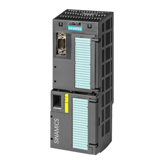
Design of the frequency converter Identifying the converter Main components of the inverter Each SINAMICS G120 inverter comprises a Control Unit and a Power Module. • The Control Unit controls and monitors the Power Module and the connected motor. • The Power Modules are available for motors with a power range of between 0.37 kW and... -
Page 16: Control Units
Design of the frequency converter 2.2 Control Units Control Units Different Control Unit versions The Control Units differ by the following main factors: ● Fieldbus interface type ● Type and scope of the functions – e.g. for CU230P-2… through additional specific technology functions for pumps, fans and compressors –... -
Page 17: Power Module
Design of the frequency converter 2.3 Power Module Power Module Which Power Module can I use with the Control Unit? Control Power Module Unit PM340 PM230 IP20 and PM230 PM240 PM240-2 PM250 PM260 PM330 push-through IP55 IP20 IP20 IP20 IP20 CU230P-2 ✓... - Page 18 Design of the frequency converter 2.3 Power Module PM240-2, 3 AC 400 V - standard areas of application, 2nd generation The PM240-2 Power Module is available without a filter or with an integrated class A line filter. The PM240-2 permits dynamic braking via an external braking resistor. Range of order numbers: 6SL3210-1PE…...
- Page 19 ● Shield connection kit for optimum shield support of the connected cables. For further information, see Overview of the shield connection kits (http://support.automation.siemens.com/WW/news/en/67225884) ● Line filter for achieving a higher radio interference suppression class. ● Line reactor for protecting the converter in harsh industrial networks.
-
Page 20: Assembling Frequency Converter Components
Design of the frequency converter 2.4 Assembling frequency converter components Assembling frequency converter components Attaching the CU Removing the CU Attaching the Operator Panel Converter with Control Units CU230P-2; CU240B-2; CU240E-2 Getting Started, 11/2013, A5E32885834B AA... -
Page 21: Iop Intelligent Operator Panel
Design of the frequency converter 2.5 IOP Intelligent Operator Panel IOP Intelligent Operator Panel The IOP is an operator device with which you can commission the frequency converter locally, enter parameters and monitor operation. The display is subdivided into various areas •... - Page 22 Design of the frequency converter 2.5 IOP Intelligent Operator Panel Menu structure The menu depicted here shows the basic structure. There are different sub-structures, depending on the software version and the Control Unit. Instead of using the application Wizards, you can also use individual parameters to directly change all of the settings.
-
Page 23: Installing
Installing Installing the Power Module WARNING Danger of death caused by high leakage currents when the external protective conductor is interrupted The inverter conducts high leakage currents > 3.5 mA via the protective conductor. When the protective conductor is interrupted, touching live components can result in electric shock, which can lead to death or serious injuries. - Page 24 Installing 3.1 Installing the Power Module Figure 3-2 Connecting the PM230 IP20 and push-through Power Module Figure 3-3 Connecting the PM230 IP55 Power Module Figure 3-4 Connecting the PM240, PM240-2 IP20 and push-through Power Module Converter with Control Units CU230P-2; CU240B-2; CU240E-2 Getting Started, 11/2013, A5E32885834B AA...
- Page 25 Installing 3.1 Installing the Power Module Figure 3-5 Connecting the PM250 Power Module Figure 3-6 Connecting the PM260 Power Module Figure 3-7 Connecting the PM330 Power Module Converter with Control Units CU230P-2; CU240B-2; CU240E-2 Getting Started, 11/2013, A5E32885834B AA...
-
Page 26: Installing Control Unit
Installing 3.2 Installing Control Unit Installing Control Unit 3.2.1 CU230P-2 control unit 3.2.1.1 Interfaces of the CU230P-2 Interfaces at the front of the Control Unit To access the interfaces at the front of the Control Unit, you must lift the Operator Panel (if one is being used) and open the front doors. - Page 27 Installing 3.2 Installing Control Unit Interfaces on the lower side of the Control Unit Converter with Control Units CU230P-2; CU240B-2; CU240E-2 Getting Started, 11/2013, A5E32885834B AA...
-
Page 28: Terminal Strips Of The Cu230P-2
Installing 3.2 Installing Control Unit 3.2.1.2 Terminal strips of the CU230P-2 *) The following applies to systems complying with UL: A maximum of 3 A 30 V DC or 2 A 250 V AC may be connected via terminals 18 / 20 (DO 0 NC) and 23 / 25 (DO 2 NC). ①... -
Page 29: Cu240B / Cu240E Control Unit
Installing 3.2 Installing Control Unit 3.2.2 CU240B / CU240E Control Unit 3.2.2.1 Interfaces of the CU240B-2 and CU240E-2 Figure 3-8 Design of the Control Unit using the example of the CU240E-2 Converter with Control Units CU230P-2; CU240B-2; CU240E-2 Getting Started, 11/2013, A5E32885834B AA... - Page 30 Installing 3.2 Installing Control Unit The converter's fieldbus interface is on the bottom of the Control Unit. Figure 3-9 Fieldbus interface allocation Converter with Control Units CU230P-2; CU240B-2; CU240E-2 Getting Started, 11/2013, A5E32885834B AA...
-
Page 31: Terminal Strips On Cu240B-2 Control Units
Installing 3.2 Installing Control Unit 3.2.2.2 Terminal strips on CU240B-2 Control Units ① The analog input is supplied from the internal 10 V voltage. ② The analog input is supplied from an external 10 V voltage. ③ Wiring when using the internal power supplies. Connection of a contact switching to P potential. ④... -
Page 32: Terminal Strips On Cu240E-2 Control Units
Installing 3.2 Installing Control Unit 3.2.2.3 Terminal strips on CU240E-2 Control Units ① The analog inputs are supplied from an external 10 V source. ② The analog inputs are supplied from the internal 10 V voltage. ③ Wiring when using the internal power supplies. Connection of a contact switching to P potential. ④... -
Page 33: Selecting The Pre-Assignment For The Terminal Strip
Installing 3.2 Installing Control Unit NOTICE Damage to the CU240E-2 PN and CU240E-2 PN-F Control Units in the event of a short- circuit of the 24 V output It is possible that the Control Units are defective if the following conditions occur simultaneously: 1. - Page 34 Installing 3.2 Installing Control Unit Macro 1: Two fixed speeds Macro 2: Two fixed speeds with safety Macro 3: Four fixed speeds function Control Units CU240E-2 Control Units CU240E-2 Control Units CU240E-2 DI 4 and DI 5 = high: the converter Several DIs = high: the converter adds adds both fixed speeds.
- Page 35 Installing 3.2 Installing Control Unit Macro 7: Switch over between fieldbus and jogging via DI 3 Control Units CU240B-2 Factory setting for converters with PROFIBUS interface PROFIdrive telegram 1 Macro 7: Switch over between fieldbus and jogging via DI 3 Macro 8: Motorized potentiometer (MOP) with safety function Control Units CU230P-2 and CU240E-2...
- Page 36 Installing 3.2 Installing Control Unit Macro 9: Motorized potentiometer Macro 9: Motorized potentiometer Macro 12: Two-wire control with (MOP) (MOP) method 1 Control Units CU240B-2 Control Units CU230P-2 and CU240E- Control Units CU240B-2 Factory setting for converters with RS485 interface Macro 12: Two-wire control with Macro 13: Setpoint via analog input method 1...
- Page 37 Installing 3.2 Installing Control Unit Macro 14: Switch over between fieldbus and motorized potentiometer (MOP) via DI 3 Control Units CU230P-2 and CU240E-2 PROFIdrive telegram 1 Macro 15: Switch over between analog setpoint and motorized potentiometer Macro 17: Two-wire control with (MOP) via DI 3 method 2 Control Units CU230P-2 and CU240E-2...
- Page 38 Installing 3.2 Installing Control Unit Macro 17: Two-wire control with Macro 19: Three-wire control with Macro 19: Three-wire control with method 2 method 1 method 1 Macro 18: Two-wire control with Control Units CU240B-2 Control Units CU230P-2 and CU240E2 method 3 Control Units CU230P-2 and CU240E2 Macro 20: Three-wire control with Macro 20: Three-wire control with...
- Page 39 Installing 3.2 Installing Control Unit Macro 21: Fieldbus USS Macro 22: Fieldbus CANopen Control Units CU230P-2 and CU240E2 Control Units CU230P-2 USS setting: 38,400 baud, 2 PZD, CANopen setting: 20 kBaud PKW variable Macro 101: Universal applications Macro 103: Pump pressure control Macro 104: ESM stairwell pressure control Control Units CU230P-2...
- Page 40 Installing 3.2 Installing Control Unit Macro 105: Fan pressure control + Macro 106: Cooling tower with active Macro 107: Cooling tower with LG- ESM with fixed setpoint sensor + hibernation Ni1000 sensor + hibernation Control Units CU230P-2 Control Units CU230P-2 Control Units CU230P-2 Converter with Control Units CU230P-2;...
-
Page 41: Wiring The Terminal Strip
Installing 3.2 Installing Control Unit 3.2.4 Wiring the terminal strip NOTICE Damage to the inverter when using long signal cables Using long cables at the inverter's digital inputs and 24 V power supply can lead to overvoltage during switching operations. Overvoltages can damage the inverter. •... -
Page 42: Description Files For Fieldbuses
See also: EMC installation guideline (http://support.automation.siemens.com/WW/view/en/60612658) 8. Use strain relief. You have now connected up the inverter's terminal strips. Description files for fieldbuses The description files contain the information required to configure and operate the converter on a fieldbus under a higher-level control. -
Page 43: Commissioning
STARTER Commissioning tool (PC software) STARTER on DVD: Connection to the inverter via USB port, PROFIBUS or 6SL3072-0AA00-0AG0 PROFINET Downloading: (http://support.automation.siemens.com/WW/view/en/1080498 5/133200) Drive ES Basic 6SW1700-5JA00-5AA0 As an option to STEP 7 with routing function via network limits for PROFIBUS and PROFINET Converter with Control Units CU230P-2;... -
Page 44: Commissioning
(Page 21)". If the IOP does not contain the actual frequency converter software, a message is displayed "Update is required". You can find the required information on the Internet at "http://support.automation.siemens.com/WW/view/de/67273266 (http://support.automation.siemens.com/WW/view/en/67273266)". In the basic commissioning, select the control mode for the motor, enter the motor data and define the pre-assignment of the frequency converter interfaces. -
Page 45: Settings In The Basic Commissioning Menu
Commissioning 4.2 Commissioning 4.2.1 Settings in the basic commissioning menu Basic commissioning The "Basic Commissioning" wizard guides you through commissioning in a maximum of 28 steps. Depending the modules and software version you are using, you can skip individual steps. Proceed as follows for the basic commissioning of the converter: Start the menu: WIZARD/BASIC COMMISSIONING and make the following settings: Input screen of the IOP... -
Page 46: Enable "Safe Torque Off" Safety Function
Commissioning 4.2 Commissioning Input screen of the IOP Selected setting on the IOP Parameter 27/21 Save settings Save Confirm with OK 28/28 Saving, please wait Confirm with OK 1) If the IOP Assistant does not offer this setting, after completing the basic commissioning, set parameter p1900 to a value of 1 using the parameter menu. - Page 47 Commissioning 4.2 Commissioning Proceed as follows in order to implement the "Safe Torque Off" safety function: Start the menu: "Basic Safety" commissioning 1/18 Enter the password for fail-safe function (factory setting = 0) Confirm with OK 2/18 If you have entered the correct password, the message "Password Confirm with OK correct"...
-
Page 48: The Most Important Parameters At A Glance
Commissioning 4.2 Commissioning 4.2.3 The most important parameters at a glance Table 4- 1 Defining the interfaces of the frequency converter Parameter Possible settings p0015 Macro drive unit Define the pre-assignment for the inputs and outputs using one of the macros 1 to 22 (Section “Selecting the pre-assignment for the terminal strip (page 33”)). - Page 49 Commissioning 4.2 Commissioning Table 4- 5 Set the USS interface Parameter Description p2020 Set the baud rate Value Baud rate Value Baud rate Value Baud rate 2400 38400 115200 4800 57600 187500 9600 76800 19200 93750 p2022 Fieldbus interface USS PZD number Sets the number of 16-bit words in the PZD part of the USS telegram Setting range: 0…...
- Page 50 Commissioning 4.2 Commissioning Table 4- 8 Motor data according to the rating plate Parameter Description p0100 Motor standard IEC/NEMA 0: Europe 50 [Hz] p0300 Motor type selection 0: No motor 1: Induction motor 2: Synchronous motor p0304 Motor voltage in [V] p0305 Motor current in [A] p0307...
- Page 51 Commissioning 4.2 Commissioning Table 4- 11 Digital outputs (relay outputs) Parameter Terminals Terminals Terminals Signal Important status signals CU240B-2 CU240E-2 CU230P-2 p0730 18 / 19 / 20 18 / 19 / 20 18 / 19 / 20 DO 0 r52.2 - operation enabled (motor running) r52.3 - fault active p0731 21 / 22...
- Page 52 Commissioning 4.2 Commissioning Table 4- 15 Analog outputs Parameter Terminals Terminals Terminals Signal Setting CU240B-2 CU240E-2 CU230P-2 p0771[0] 12 / 13 12 / 13 12 / 13 AO 0 Important status signals: 0: Analog output locked p0771[1] 26 / 27 26 / 27 AO 1 21: Speed actual value...
-
Page 53: More Information
Chinese with CU240E Control Units operating fail-safe functions of the inverter. List Manual Graphic function block English, for the SINAMICS G120 inverter with diagrams. German, Control Units CU230P-2 and Control Chinese List of all parameters, Units CU240B-2; CU240E-2 alarms and faults. -
Page 54: Product Support
5.2 Product support Depth of Manual Contents Languages Download or order number information Hardware Installation Manual Installing power German, for the following SINAMICS G120 modules, reactors and English Power Modules: filters. Maintaining power PM230 IP20 • modules. PM230 IP55 •...