Makita DBN600 Repair Manual
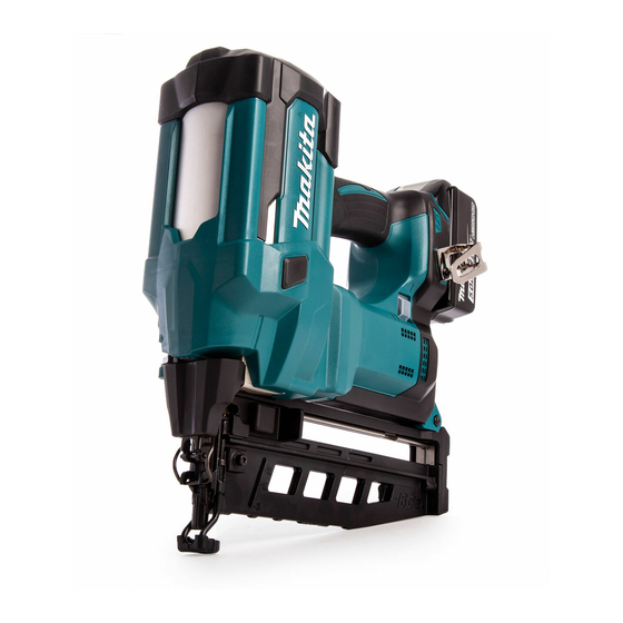
Cordless brad nailer
Hide thumbs
Also See for DBN600:
- Instruction manual (85 pages) ,
- Instruction manual (13 pages) ,
- Instruction manual (57 pages)

Related Manuals for Makita DBN600


Summary of Contents for Makita DBN600
- Page 1 OFFICIAL USE for ASC & Sales Shop CORDLESS BRAD NAILER DBN600 REPAIR MANUAL March 2018 Ver.1...
-
Page 2: Table Of Contents
OFFICIAL USE for ASC & Sales Shop CONTENTS CONTENTS ....................................2 CAUTION ....................................3 NECESSARY REPAIRING TOOLS ............................3 LUBRICANT AND ADHESIVE APPLICATION ........................4 TIGHTENING TORQUE SPECIFICATIONS ..........................4 REPAIR ......................................6 Magazine section.................................. 6 6-1-1 Disassembling ................................6 6-1-2 Assembling .................................. -
Page 3: Caution
OFFICIAL USE for ASC & Sales Shop CAUTION Repair the machine in accordance with “Instruction manual” or “Safety instructions”. Follow the instructions described below in advance before repairing: Wear gloves. In order to avoid wrong reassembly, draw or write down where and how the parts are assembled, and what the parts are. It is also recommended to have boxes ready to keep disassembled parts by group. -
Page 4: Lubricant And Adhesive Application
OFFICIAL USE for ASC & Sales Shop LUBRICANT AND ADHESIVE APPLICATION Description Amount Isoflex NB52 A little if not indicated TIGHTENING TORQUE SPECIFICATIONS 4 / 41... - Page 5 OFFICIAL USE for ASC & Sales Shop Parts to fasten Fastener Tightening torque (N・m) Quantity M5x18 Hex socket Top cap Main cylinder 4.5 – 6.5 *1 head bolt M4x12 Hex socket Top cap Stem holder 2.7 – 4.2 head bolt Shaft Crank Shaft...
-
Page 6: Repair
OFFICIAL USE for ASC & Sales Shop REPAIR Note: Be sure to remove battery and Nails before reparing. Magazine section 6-1-1 Disassembling Fig. 1 1 1 1 1 Remove an M5x28 Pan head screw [2] and 3x16 Tapping screws [3] (12 pcs) from Housing L [1]. Then remove Housing R [4]. - Page 7 OFFICIAL USE for ASC & Sales Shop Fig. 3 3 3 3 3 Compress [3] Compression spring 9 [2] using Slotted screwdriver [1]. Remove Compression spring 9 [2] from Adjuster base [4]. Fig. 4 [10] 4 4 4 4 Remove [6] the bent portion of Arm [4] from Adjuster base [5] while lifting up [3] Driver guide [1] by turning [2] it.
- Page 8 OFFICIAL USE for ASC & Sales Shop Fig. 5 [4、5] 5 5 5 5 Remove M4x12 Hex socket head bolts [4] (2 pcs) and Sleeves 4 [5] (2 pcs) from Driver guide [3] by supporting [2] Pusher lever [1]. Remove [7] Driver guide section [3] from Magazine section [6]. ・Guide plate [8] Note Be sure not to lose Sleeve 4 [5].
-
Page 9: Assembling
OFFICIAL USE for ASC & Sales Shop Fig. 7 7 7 7 7 Remove 3x16 Tapping screws [2] (2 pcs) from Magazine [1]. Remove Magazine end [3] and End plate [4]. 6-1-2 Assembling 1 1 1 1 Reverse the procedure. (6-1-1) Fig. - Page 10 OFFICIAL USE for ASC & Sales Shop Fig. 10 4 4 4 4 Set [4] to Magazine [3] by supporting [2] Spiral spring [1] so that Spiral spring [1] does not come off. Fig. 11 1R268 [10] [11] 5 5 5 5 Set [8] the protrusion of Pusher lever [6] in the groove of Magazine end [7] while setting [5] Pusher [3] in the groove of Magazine [4] by pushing [2] Button [1].
- Page 11 OFFICIAL USE for ASC & Sales Shop 7 7 7 7 Set [5] the groove of Nail rail [3] in Pusher [4] while pushing [2] Button [1] of (Fig. 11) and aligning the cutout portion of Nail rail [3] to the arrowed direction. Set [7] the edge of Nail rail [3] to the groove of End plate [6]. Fig.
-
Page 12: Armature And Gear Assembly
OFFICIAL USE for ASC & Sales Shop Fig. 16 Set to Housing so that the bent portion of Arm [1] comes closer to the Trigger side [3] than Leaf spring [2]. Fig. 17 Facing the flat sides of Driver [1] to the door side [2], and applying the side surface of Driver guide [3] to the side surface of Crank case [4], tighten M5x25 Hex socket head bolts [5] (2 pcs). - Page 13 OFFICIAL USE for ASC & Sales Shop Fig. 19 3 3 3 3 Remove M4x16 Hex socket head bolts [2] (4 pcs) from Crank case [1]. Remove [6] Flat washer 23 [3], Gear assembly [4] and Motor housing [5]. Note Be sure not to lose Flat washer 23 [3].
- Page 14 OFFICIAL USE for ASC & Sales Shop Fig. 22 6 6 6 6 Remove [3] Gear assembly [2] from Motor housing [1]. Fig. 23 7 7 7 7 Remove 3x16 Tapping screws [2] (4 pcs) from Motor housing L [1]. Remove Motor housing R [3]. Fig.
-
Page 15: Assembling
OFFICIAL USE for ASC & Sales Shop Fig. 25 9 9 9 9 Hook [3] Torsion spring [1] to the groove of Brush holder [2]. Float [6] Carbon brush [5]. Tips Hold the illustrated parts [4] so that Torsion spring [1] does not come off. - Page 16 OFFICIAL USE for ASC & Sales Shop Fig. 28 Facing the cutout portion of York unit [1] to the gear side of Armature [2], assemble them. Fig. 29 Assemble Armature [1] and York unit [2] to Brush holder [3]. Fig. 30 Set Torsion spring [2] that is hooked to the groove of Brush holder side [1] to the initial position [3].
- Page 17 OFFICIAL USE for ASC & Sales Shop Fig. 31 Assemble by facing the cutout portion of York unit [1] to the protrusion of Motor housing L [2]. Tips ・ Be sure that the flat surface of Brush holder [4] is fit vertically when viewed from arrow side [3]. ・...
- Page 18 OFFICIAL USE for ASC & Sales Shop Fig. 33 Align Plate [1] and Gear assembly [2] as shown. Align the other side of Plate [1] to the groove of Motor housing [3]. Opposite side can be done in the same way. Fig.
- Page 19 OFFICIAL USE for ASC & Sales Shop Fig. 35 Assemble Flat washer 23 [2] to Gear assembly [1]. Set Gear assembly [1] by aligning [5] the hexagonal part [4] of Shaft [4] to the hexagonal part [3] of Gear assembly [1]. Setting the protrusion [6] of Gear assembly [1], tighten with M4x16 Hex socket head bolts [7] (4 pcs) applied a little bit of Loctite 272.
-
Page 20: Crank Section, Main Piston Section And Driver
OFFICIAL USE for ASC & Sales Shop Crank section, Main piston section and Driver 6-3-1 Disassembling Remove Housing R, Driver guide and Magazine. (6-1-1) Remove Gear assembly and Motor housing. (6-2-1) Fig. 36 Remove M5x12 Hex bolts [2] (2 pcs) from Top cap [1]. Remove [6] Spring bracket [3], Rear cushion [4] and Compression spring 15 [5]. - Page 21 OFFICIAL USE for ASC & Sales Shop Fig. 38 Push through [3] Head valve [2] from Top cap [1]. Fig. 39 Remove [3] Cushion P [2] from Head valve [1]. Fig. 40 Remove M4x12 Hex socket head bolts [2] (2 pcs) from Top cap [1]. Remove [4] Stem holder [3]. Note Be sure that O ring 6 [5] does not come off.
- Page 22 OFFICIAL USE for ASC & Sales Shop Fig. 41 Remove M4x28 Hex socket head bolts [2] (4 pcs) from Main cylinder [1]. Remove [6] Crank case [3], Driver [4] and Main piston [5]. Fig. 42 Remove [3] Con-rod [2] from Crank [1]. Fig.
- Page 23 OFFICIAL USE for ASC & Sales Shop Fig. 44 Remove O ring 80 [2] and Stopper [3] from Main piston [1]. Pull out [5] Piston pin 8 [4] and remove [7] Con-rod [6] from Main piston [1]. Fig. 45 Inserting Slotted screwdriver [1] to the gap [4] between Front cushion [2] and Crank case [3], prying it up [5], remove [6] Front cushion [2] from Crank case [3].
- Page 24 OFFICIAL USE for ASC & Sales Shop Fig. 46 Remove M4x12 Hex socket head bolt [2] from Crank case [1]. Remove [4] Spur gear 14 section [3]. Fig. 47 1R267 1R258 Supporting Holder [1] with 1R258, tapping [3] Spring pin 2.5-9 [2] with 1R267, remove [7] Spur gear 44 [4], Bracket [5] and Holder [6].
-
Page 25: Assembling
OFFICIAL USE for ASC & Sales Shop Fig. 49 [12] [13] [10] 1R041 [11] [14] Fixing the flat two surfaces of the edge [3] of Crank [2] with Vice [1] and 1R041, and using Nut spinner handle [4], Bit adapter assembly [5] and Socket bit 13 [6], remove [10] Crank [2] and Spur gear 44 [9] by turning Shaft [7] counterclockwise [8]. - Page 26 OFFICIAL USE for ASC & Sales Shop Fig. 50 1R220 1R219 1R222 1R041 Fixing the flat two surfaces of the edge [3] of Crank [2] with Vice [1] and 1R041, setting 1R219 to 15-18 N・m, using 1R220, 1R222, Bit adapter assembly [4] and Socket bit 13 [5], tighten Shaft [6] by turning it clockwise [7]. Fig.
- Page 27 OFFICIAL USE for ASC & Sales Shop Fig. 52 [10] Aligning [3] the two surfaces of Bracket [2] to the groove of Crank case [1], assembling Spur gear 44 [4] while being careful of the engaged position (see the Note below) with Spur gear 44 [4] of Crank side [5], tighten M4x12 Hex socket head bolt [7] (1 pc).
- Page 28 OFFICIAL USE for ASC & Sales Shop Fig. 54 Inserting Con-rod [1] to Main piston [3] as shown [2], insert [5] Piston pin 8 [4] to all the way inside. Fig. 55 Fit up [3] Rubber ring [1] to the position that seals the Cylinder’s holes [2].
- Page 29 OFFICIAL USE for ASC & Sales Shop Fig. 57 Cover [3] Main piston [2] with Main cylinder [1]. Put a little bit of Loctite 272 on M4x28 Hex socket head bolts [4] (4 pcs). Fasten Crank case [5] to Main cylinder [1]. Fig.
- Page 30 OFFICIAL USE for ASC & Sales Shop Fig. 59 Push [4] Cushion P [1] to Head valve [3] with stepped side of Cushion P set [2] as shown. Fig. 60 Aligning [5] the protrusion [2] of Head valve [1] to the groove [4] of Top cap [3], push [6] Head valve [1]. Fig.
-
Page 31: Door Section
OFFICIAL USE for ASC & Sales Shop Fig. 62 Insert [3] Compression spring 15 [1] into Head valve [2]. Insert Rear cushion [4] into Top cap [5]. Supporting [8] Spring bracket [7], put a little bit of Loctite 272 on M5x12 Hex bolts (2 pcs) [9]. Fasten Spring bracket [7] to Top cap [5]. -
Page 32: Assembling
OFFICIAL USE for ASC & Sales Shop Fig. 64 1R268 1R026 Supporting Latch [1] with 1R026 etc., tap [3] Spring pin 3-22 [2] with 1R268 and remove [5] Latch [1] from Door [4]. Fig. 65 Pinching [3] Headed pin 3 [2] with Long nose pliers [1], remove [5] Urethane washer [4]. Pull out [6] Headed pin 3 [2] and remove [9] Plate [8] from Door [7]. - Page 33 OFFICIAL USE for ASC & Sales Shop Fig. 67 1R268 1R026 Set Latch [2] to Door [1] as shown. Supporting Latch [2] with 1R026 etc., tap [4] Spring pin 3-22 [3] with 1R268. Pushing to the other side [6] of Water pump plier [5], tap Spring pin 3-22 [3] again. Set the Spring pin 3-22 [3] as shown.
-
Page 34: Arm Section, Contact Top, Driver Guide
OFFICIAL USE for ASC & Sales Shop Fig. 68 Press into [4] the groove [3] of Latch cover [2] to Latch [1]. Push into [6] the shown part [5] of Latch cover [2] and fit in the groove [7] of Latch [1]. Arm section, Contact top, Driver guide 6-5-1 Disassembling... - Page 35 OFFICIAL USE for ASC & Sales Shop Fig. 69 Remove [3] Driver guide [2] from Contact top [1]. Fig. 70 Remove [3] Stop ring E-3 [2] using Precision driver [1]. Fig. 71 Remove Contact top [1] by turning it counterclockwise [2]. 35 / 41...
- Page 36 OFFICIAL USE for ASC & Sales Shop Fig. 72 Remove parts from Arm [6] by fixing Adjuster shaft [2] with Wrench 8 [1] and turning M8 Hex nut [4] with Wrench 13 [3] counterclockwise [5]. Note Do not lose Steel ball 3 [7] and Compression spring 2 [8]. ・...
-
Page 37: Assembling
OFFICIAL USE for ASC & Sales Shop Fig. 74 Remove O rings 3 [1] (2 pcs). 6-5-2 Assembling Reverse the procedure (6-5-1). Pusher section 6-6-1 Disassembling Remove Pusher lever section from Magazine. (6-1-1) Fig. 75 Disassembled parts are as follow when 3x8 Tapping screw [1] gets removed: ・... -
Page 38: Circuit Diagram
OFFICIAL USE for ASC & Sales Shop CIRCUIT DIAGRAM Fig. 76 Color index of lead wires' sheath White Blue Yellow Orange Gray Purple Green Brown Black 38 / 41... - Page 39 OFFICIAL USE for ASC & Sales Shop Flag receptacle (without lock/#187/t=0.5) Brush holder Receptacle sleeve Switch unit Switch unit Switch unit (mode selection) (for contact (for arm) trigger) Print circuit LED circuit board AWG 24 AWG 24 AWG 16 AWG 16 (Crank shaft sensor)...
-
Page 40: Wiring Diagram
OFFICIAL USE for ASC & Sales Shop WIRING DIAGRAM Fig. 77 ●Put LED in Housing L so that the lead wire comes from the back side. lead wires ●Put connected to LED in the groove A and B. ●Put lead wires for Switch unit (for Contact arm) in these grooves. - Page 41 OFFICIAL USE for ASC & Sales Shop Fig. 78 ●Put the protrusion of Closed end splice connected to lead wires (red, red) in the space circled with dots. ※Do not put as shown on the right <NG example>. <NG example> protrusion protrusion Closed end splice...