Table of Contents
Advertisement
Contents
Component Overview . . . . . . . . . . . . . . . .2
Quick Start Installation Instructions . . . . . .3
Detailed Installation Instructions . . . . . . . .4
• Mounting the Receiver . . . . . . . . . . . . .4
• Receiver Control Wire Connection . . .4-5
• Receiver Power Wire Connection . . . . .6
• Initial Receiver Testing . . . . . . . . . . . . .7
• Rainfall Adjustment . . . . . . . . . . . . . . .7
• Testing Signal Strength . . . . . . . . . . . .7
• Testing Control System Operation . . . .7
• Installing the Sensor/Transmitter . . . . .8
Wireless RainSensor Operation . . . . . . . .9
• Normal Operation . . . . . . . . . . . . . . . . .9
• Smart Bypass . . . . . . . . . . . . . . . . . . .9
• Power Down . . . . . . . . . . . . . . . . . . . .9
• Receiver Learn Mode . . . . . . . . . . . . . .9
• Attention Required . . . . . . . . . . . . . . . .9
Battery Replacement . . . . . . . . . . . . . . .10
Changing Sensor/Transmitter Code . . . .10
Troubleshooting . . . . . . . . . . . . . . . . .10-11
Electromagnetic Compatibility . . . . . . . . .11
Specifications . . . . . . . . . . . . . . . . . . . . .12
Warranty . . . . . . . . . . . . . . . . . . . . . . . .12
Introduction
The Toro Wireless RainSensor connects to your irrigation system controller/timer to
suspend automatic watering operation in the event of rain. Designed for ease of
installation, your sensor-controlled irrigation system will be up and running in minutes.
Before attempting the installation, please read through these instructions in their
entirety, and refer the installation instructions for your irrigation system controller/timer
in regards to connecting a rain sensor or rain switch. The Wireless RainSensor is
designed to work with either Normally Open or Normally Closed sensor circuits.
Important: Please note the following information regarding installation and use
of the Wireless RainSensor components:
• The RainSensor Receiver is designed to operate with 24 V ac power only.
Connecting the Receiver wiring to 120/240 V ac power may result in severe
equipment damage.
• Installation methods must comply with all applicable national and local building
codes. If you are unsure about proper wiring practices, have a qualified contrac-
tor perform the installation for you.
• The Receiver cover should always be used when the Receiver is installed out-
doors.
• The Sensor/Transmitter should never be submerged in water or installed inside a
rain gutter.
Wireless RainSensor
Model 53770
User's Guide
Page
. . . . . .7
Sensor/Transmitter
™
Receiver
Advertisement
Table of Contents

Related Manuals for Toro Wireless RainSensor 53770


Summary of Contents for Toro Wireless RainSensor 53770
-
Page 1: Table Of Contents
Warranty ......12 Introduction The Toro Wireless RainSensor connects to your irrigation system controller/timer to suspend automatic watering operation in the event of rain. Designed for ease of installation, your sensor-controlled irrigation system will be up and running in minutes. -
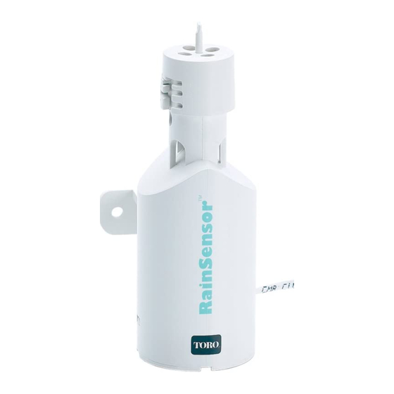
Page 2: Component Overview
Component Overview Receiver (Figure 1) Figure 1 1 - Weather-resistant Cover: Slides upward to remove. Protects the Receiver module when located outdoors. Keep the cover installed at all times other than when manu- ally operating the Receiver. 2 - Antenna wire: Straighten the antenna wire verti- cally for the best reception. -
Page 3: Quick Start Installation Instructions
Quick Start Installation Instructions The following instructions are provided for the experienced installer. If you are installing a Toro Wireless Rainsensor for the first time, use the Detailed Installation Instructions starting on page 4. 1. Disconnect power to the irrigation system controller. -
Page 4: Detailed Installation Instructions
White Common Wire From Valves Yellow* Note: Use the Yellow wire in place of the Brown wire if the controller requires a Normally Open sensor. For example, the Toro ECx and GreenKeeper ® controllers. Locate the controller sensor terminals (generally marked “SENSOR”, “SEN” or “S”) and directly connect the White and Brown* wires to these terminals in any order. - Page 5 Controllers with no sensor inputs and no pump start or master valve: Irrigation System Controller PUMP/ 24 VAC To Valves Brown White Common Wire From Valves Yellow- Not Used Wire Connector Remove the valve common wire from the valve common terminal (generally marked “C”, “COM”, or “VC”).
-
Page 6: Receiver Power Wire Connection
Part 2 - Power Wire Connection Note: The Receiver requires 24 V ac to operate. It should only be connected to an irrigation controller that uses a 24 V ac UL listed Class 2 transformer to supply power. Caution: Do not connect the Receiver directly to 120/240 V ac power as this may result in irreversible damage. -
Page 7: Initial Receiver Testing
Initial Receiver Testing Reconnect power to the controller and verify the Receiver’s Power Indicator is illumi- nated. Hold the Sensor/Transmitter at close range to the Receiver, then lightly press and hold the Test Spindle. The Sensor Status Indicator should illuminate and remain on until the Test Spindle is released. - Page 8 Installation Procedure The Sensor/Transmitter should be mounted vertically with the antenna wire extending straight down. Avoid installations where the antenna wire would contact any metal object. Figure 7 Thumbscrew Antenna wire extended straight down Rain gutter (cross section view) A rain gutter is an ideal location for the Sensor/Transmitter. Simply position the bracket with the thumbscrew under the gutter lip and tighten to secure (do not over-tighten).
-
Page 9: Wireless Rainsensor Operation
RainSensor Operation Normal Operation When the RainSensor activates due to sufficient rainfall, the Sensor Status Indicator will remain illuminated on the Receiver and the sprinkler system will remain inactive until the moisture-absorbent discs inside the Sensor/Transmitter have dried out. The rate at which the discs dry out will vary dependent on ambient conditions such as temperature, sun exposure, humidity and wind—... -
Page 10: Battery Replacement
Sensor/Transmitter Battery Replacement 1. Remove the bottom housing cover of the Figure 9 Sensor/Transmitter by gently pressing in and down on the lower opposing tabs using a small flat-blade screwdriver, then carefully slide the circuit board out. See Figure 9. 2. -
Page 11: Electromagnetic Compatibility
The obstacles will all affect the transmitted signal and typically reduce the radiated power that will be read by the Receiver. Different objects such as walls and floors affect the transmitted signal differently depending on the material composition, geom- etry and thickness. Typically, most residential and light commercial construction mate- rials do not reduce the effective transmitted signal enough to pose problems under normal installation conditions. -
Page 12: Specifications
Neither The Toro Company nor Toro Warranty Company is liable for failure of products not manufactured by them even though such products may be sold or used in conjunction with Toro products.