Emerson Micro Motion 1700 Configuration And Use Manual
Transmitters with
analog outputs
Hide thumbs
Also See for Micro Motion 1700:
- Configuration and use manual (328 pages) ,
- Installation manual (122 pages) ,
- Product data sheet (28 pages)

Related Manuals for Emerson Micro Motion 1700


Summary of Contents for Emerson Micro Motion 1700
- Page 1 Configuration and Use Manual MMI-20019028, Rev AB March 2018 ® Micro Motion Model 1700 Transmitters with Analog Outputs Configuration and Use Manual...
- Page 2 Micro Motion employees. Micro Motion will not accept your returned equipment if you fail to follow Micro Motion procedures. Return procedures and forms are available on our web support site at www.emerson.com, or by phoning the Micro Motion Customer Service department.
-
Page 3: Table Of Contents
Contents Contents Part I Getting started Chapter 1 Before you begin ......................3 About this manual ......................... 3 Transmitter model code ........................ 3 Communications tools and protocols .................... 4 Additional documentation and resources ..................4 Chapter 2 Quick start ........................5 Power up the transmitter .......................5 Check meter status ........................6 2.2.1... - Page 4 Contents 4.5.2 Configure two-phase flow parameters ................40 4.5.3 Configure Density Damping ..................42 4.5.4 Configure Density Cutoff ....................43 Configure temperature measurement ..................44 4.6.1 Configure Temperature Measurement Unit ..............44 4.6.2 Configure Temperature Damping ................44 4.6.3 Effect of Temperature Damping on process measurement ........... 45 4.6.4 Configure Temperature Input ..................
- Page 5 Contents 6.3.2 Configure Frequency Output Scaling Method ...............81 6.3.3 Configure Frequency Output Fault Action and Frequency Output Fault Level ....82 Configure the Discrete Output ....................83 6.4.1 Configure Discrete Output Source ................84 6.4.2 Configure Discrete Output Polarity ................86 6.4.3 Configure Discrete Output Fault Action ................86 Configure events .........................
- Page 6 Contents Zero the meter .......................... 134 Validate the meter ........................135 9.6.1 Alternate method for calculating the meter factor for volume flow ......136 Perform a (standard) D1 and D2 density calibration ..............137 9.7.1 Perform a D1 and D2 density calibration using ProLink III ..........138 9.7.2 Perform a D1 and D2 density calibration using the Field Communicator .....
- Page 7 Contents Appendices and reference Appendix A Using the transmitter display ..................189 Components of the transmitter interface .................. 189 Use the optical switches ......................190 Access and use the display menu system ................... 191 A.3.1 Enter a floating-point value using the display .............. 192 Display codes for process variables ....................
- Page 8 Contents Micro Motion Model 1700 Transmitters with Analog Outputs...
-
Page 9: Part I Getting Started
Getting started Part I Getting started Chapters covered in this part: • Before you begin • Quick start Configuration and Use Manual... - Page 10 Getting started Micro Motion Model 1700 Transmitters with Analog Outputs...
-
Page 11: Before You Begin
Before you begin Before you begin Topics covered in this chapter: • About this manual • Transmitter model code • Communications tools and protocols • Additional documentation and resources About this manual This manual helps you configure, commission, use, maintain, and troubleshoot Micro Motion Model 1700 transmitters with analog outputs. -
Page 12: Communications Tools And Protocols
Topic Document Hazardous area installa- See the approval documentation shipped with the transmitter, or tion download the appropriate documentation at www.emerson.com. ™ Product Data Sheet Micro Motion Series 1000 and Series 2000 Transmitters with MVD Tech‐ nology Product Data Sheet... -
Page 13: Chapter 2 Quick Start
Quick start Quick start Topics covered in this chapter: • Power up the transmitter • Check meter status • Make a startup connection to the transmitter • (Optional) Adjust digital communications settings • Verify mass flow measurement • Verify the zero Power up the transmitter The transmitter must be powered up for all configuration and commissioning tasks, or for process measurement. -
Page 14: Check Meter Status
Quick start Check meter status Check the meter for any error conditions that require user action or that affect measurement accuracy. Wait approximately 10 seconds for the power-up sequence to complete. Immediately after power-up, the transmitter runs through diagnostic routines and checks for error conditions. -
Page 15: Make A Startup Connection To The Transmitter
Quick start Make a startup connection to the transmitter For all configuration tools except the display, you must have an active connection to the transmitter to configure the transmitter. Follow this procedure to make your first connection to the transmitter. Identify the connection type to use, and follow the instructions for that connection type in the appropriate appendix. -
Page 16: Verify The Zero
Quick start On-Line Menu > Overview > Primary Purpose Variables Postrequisites If the reported mass flow rate is not accurate: • Check the characterization parameters. • Review the troubleshooting suggestions for flow measurement issues. Verify the zero Verifying the zero helps you determine if the stored zero value is appropriate to your installation, or if a field zero can improve measurement accuracy. -
Page 17: Terminology Used With Zero Verification And Zero Calibration
Quick start d. Repeat the zero verification procedure. e. If it fails again, zero the meter. Postrequisites Restore normal flow through the sensor by opening the valves. Related information Zero the meter 2.6.1 Terminology used with zero verification and zero calibration Term Definition... - Page 18 Quick start Micro Motion Model 1700 Transmitters with Analog Outputs...
-
Page 19: Part Ii Configuration And Commissioning
Configuration and commissioning Part II Configuration and commissioning Chapters covered in this part: • Introduction to configuration and commissioning • Configure process measurement • Configure device options and preferences • Integrate the meter with the control system Complete the configuration •... - Page 20 Configuration and commissioning Micro Motion Model 1700 Transmitters with Analog Outputs...
-
Page 21: Introduction To Configuration And Commissioning
Introduction to configuration and commissioning Introduction to configuration and commissioning Topics covered in this chapter: • Configuration flowchart • Default values and ranges • Enable access to the off‐line menu of the display • Disable write‐protection on the transmitter configuration •... - Page 22 Introduction to configuration and commissioning Figure 3-1: Configuration flowchart Configure device options and Test and move to production Configure process measurement preferences Configure mass flow Test or tune transmitter Configure display measurement using sensor simulation parameters Configure volume flow meaurement Configure fault handling Back up transmitter parameters...
-
Page 23: Default Values And Ranges
Introduction to configuration and commissioning Default values and ranges Section D.1 to view the default values and ranges for the most commonly used parameters. Enable access to the off-line menu of the display Display OFF-LINE MAINT > OFF-LINE CONFG > DISPLAY ProLink III Device Tools >... -
Page 24: Restore The Factory Configuration
Introduction to configuration and commissioning Restore the factory configuration Display Not available ProLink III Device Tools > Configuration Transfer > Restore Factory Configuration Field Communicator Service Tools > Maintenance > Reset/Restore > Restore Factory Configuration Overview Restoring the factory configuration returns the transmitter to a known operational configuration. -
Page 25: Configure Process Measurement
Configure process measurement Configure process measurement Topics covered in this chapter: • Configure mass flow measurement • Configure volume flow measurement for liquid applications • Configure GSV flow measurement • Configure Flow Direction • Configure density measurement • Configure temperature measurement •... - Page 26 Configure process measurement Options for Mass Flow Measurement Unit The transmitter provides a standard set of measurement units for Mass Flow Measurement Unit, plus one user-defined special measurement unit. Different communications tools may use different labels for the units. Label Display ProLink III Field Communica-...
- Page 27 Configure process measurement Define a special measurement unit for mass flow Display Not available ProLink III Device Tools > Configuration > Process Measurement > Flow > Special Units Field Communicator Configure > Manual Setup > Measurements > Special Units > Mass Special Units Overview A special measurement unit is a user-defined unit of measure that allows you to report process data, totalizer data, and inventory data in a unit that is not available in the...
-
Page 28: Configure Flow Damping
Configure process measurement a. 1 lb/sec = 16 oz/sec b. Mass Flow Conversion Factor = 1 ÷ 16 = 0.0625 Set Mass Flow Conversion Factor to 0.0625. Set Mass Flow Label to oz/sec. Set Mass Total Label to oz. 4.1.2 Configure Flow Damping Display Not available... -
Page 29: Configure Mass Flow Cutoff
Configure process measurement Effect of flow damping on volume measurement Flow damping affects volume measurement for liquid volume data. Flow damping also affects volume measurement for gas standard volume data. The transmitter calculates volume data from the damped mass flow data. Interaction between Flow Damping and mA Output Damping In some circumstances, both Flow Damping and mA Output Damping are applied to the... -
Page 30: Configure Volume Flow Measurement For Liquid Applications
Configure process measurement Interaction between Mass Flow Cutoff and mA Output Cutoff Mass Flow Cutoff defines the lowest mass flow value that the transmitter will report as measured. mA Output Cutoff defines the lowest flow rate that will be reported via the mA output. -
Page 31: Configure Volume Flow Type For Liquid Applications
Configure process measurement Restriction You cannot implement both liquid volume flow and gas standard volume flow at the same time. Choose one or the other. Note If you need to switch from gas standard volume to liquid volume, polling for base density will automatically be disabled. - Page 32 Configure process measurement Prerequisites Before you configure Volume Flow Measurement Unit, be sure that Volume Flow Type is set to Liquid. Procedure Set Volume Flow Measurement Unit to the unit you want to use. The default setting for Volume Flow Measurement Unit is l/sec (liters per second). If the measurement unit you want to use is not available, you can define a special measurement unit.
- Page 33 Configure process measurement Label Unit description Display ProLink III Field Communicator UKGPH Imp gal/hr Impgal/h Imperial gallons per hour UKGPD Imp gal/day Impgal/d Imperial gallons per day BBL/S barrels/sec bbl/s Barrels per second BBL/MN barrels/min bbl/min Barrels per minute Barrels per hour BBL/H barrels/hr bbl/h...
-
Page 34: Configure Volume Flow Cutoff
Configure process measurement Calculate Volume Flow Conversion Factor as follows: a. x base units = y special units b. Volume Flow Conversion Factor = x ÷ y Enter Volume Flow Conversion Factor. The original volume flow rate value is divided by this conversion factor. Set Volume Flow Label to the name you want to use for the volume flow unit. -
Page 35: Configure Gsv Flow Measurement
Configure process measurement Interaction between Volume Flow Cutoff and mAO Cutoff Volume Flow Cutoff defines the lowest liquid volume flow value that the transmitter will report as measured. mAO Cutoff defines the lowest flow rate that will be reported via the mA Output. -
Page 36: Configure Volume Flow Type For Gas Applications
Configure process measurement Restriction You cannot implement both liquid volume flow and gas standard volume flow at the same time. Choose one or the other. 4.3.1 Configure Volume Flow Type for gas applications Display Not available ProLink III Device Tools > Configuration > Process Measurement > Flow Field Communicator Configure >... - Page 37 Configure process measurement Option Description Fixed Value or Digital A host writes gas base density data to the meter at appropriate intervals. Communications Continue to Configure fixed value or digital communications. Poll for external value The meter polls an external HART device for gas base density data in order to then compute gas standard volume from the mass flow and gas base density.
-
Page 38: Configure Gas Standard Volume Flow Unit
Configure process measurement • The device being polled (slave) cannot have special units set for density. Otherwise, the master will reject the base density and report the following alarm: A115: No External Input or Polled Data Alert • On the slave side, setup the HART Primary Variable for Base Density. The master will reject anything other than Base Density for the HART Primary Variable and trigger an A115 alarm. - Page 39 Configure process measurement Options for Gas Standard Volume Flow Unit The transmitter provides a standard set of measurement units for Gas Standard Volume Flow Unit, plus one user-defined special measurement unit. Different communications tools may use different labels for the units. Label Unit description Display...
- Page 40 Configure process measurement Overview A special measurement unit is a user-defined unit of measure that allows you to report process data, totalizer data, and inventory data in a unit that is not available in the transmitter. A special measurement unit is calculated from an existing measurement unit using a conversion factor.
-
Page 41: Configure Gas Standard Volume Flow Cutoff
Configure process measurement Set Gas Standard Volume Total Label to MSCF. 4.3.4 Configure Gas Standard Volume Flow Cutoff Display Not available ProLink III Device Tools > Configuration > Process Measurement > Flow Field Communicator Configure > Manual Setup > Measurements > GSV > GSV Cutoff Overview Gas Standard Volume Flow Cutoff specifies the lowest gas standard volume flow rate that will reported as measured. -
Page 42: Configure Flow Direction
Configure process measurement Example: Cutoff interaction with mA Output Cutoff higher than Gas Standard Volume Flow Cutoff Configuration: • mA Output Process Variable for the primary mA Output: Gas Standard Volume Flow Rate • Frequency Output Process Variable: Gas Standard Volume Flow Rate •... -
Page 43: Options For Flow Direction
Configure process measurement 4.4.1 Options for Flow Direction Flow Direction setting Relationship to Flow Direction arrow ProLink III Field Communicator on sensor Forward Forward Appropriate when the Flow Direction ar- row is in the same direction as the major- ity of flow. Reverse Reverse Appropriate when the Flow Direction ar-... - Page 44 Configure process measurement Figure 4-1: Effect of Flow Direction on the mA Output: Lower Range Value = 0 Flow Direction = Forward Flow Direction = Reverse, Negate Forward Flow Direction = Absolute Value, Bidirectional, Negate Bidirectional Reverse flow Forward flow Reverse flow Forward flow Reverse flow...
- Page 45 Configure process measurement Result: • Under conditions of zero flow, the mA Output is 4 mA. • Under conditions of forward flow, up to a flow rate of 100 g/sec, the mA Output varies between 4 mA and 20 mA in proportion to the flow rate. •...
- Page 46 Configure process measurement Effect of flow direction on Frequency Outputs Flow direction affects how the transmitter reports flow values via the Frequency Outputs. The Frequency Outputs are affected by flow direction only if Frequency Output Process Variable is set to a flow variable. Table 4-1: Effect of the flow direction parameter and actual flow direction on Frequency Outputs...
-
Page 47: Configure Density Measurement
Configure process measurement Table 4-3: Effect of the flow direction on flow values Actual flow direction Flow Direction setting Forward Zero flow Reverse Forward Positive Negative Reverse Positive Negative Bidirectional Positive Negative Absolute Value Positive Positive Negate Forward Negative Positive Negate Bidirectional Negative Positive... -
Page 48: Configure Two-Phase Flow Parameters
Configure process measurement Procedure Set Density Measurement Unit to the option you want to use. The default setting for Density Measurement Unit is g/cm3 (grams per cubic centimeter). Options for Density Measurement Unit The transmitter provides a standard set of measurement units for Density Measurement Unit. - Page 49 Configure process measurement Procedure Set Two-Phase Flow Low Limit to the lowest density value that is considered normal in your process. Values below this will cause the transmitter to post Alert A105 (Two-Phase Flow). Gas entrainment can cause your process density to drop temporarily. To reduce the occurrence of two-phase flow alerts that are not significant to your process, set Two-Phase Flow Low Limit slightly below your expected lowest process density.
-
Page 50: Configure Density Damping
Configure process measurement • The two-phase flow alert is deactivated, but remains in the active alert log until it is acknowledged. If the two-phase flow condition does not clear before Two-Phase Flow Timeout expires, the outputs that represent flow rate report a flow rate of 0. If Two-Phase Flow Timeout is set to 0.0 seconds, the outputs that represent flow rate will report a flow rate of 0 as soon as two-phase flow is detected. -
Page 51: Configure Density Cutoff
Configure process measurement • Whenever the damping value is non-zero, the reported measurement will lag the actual measurement because the reported value is being averaged over time. • In general, lower damping values are preferable because there is less chance of data loss, and less lag time between the actual measurement and the reported value. -
Page 52: Configure Temperature Measurement
Configure process measurement Configure temperature measurement The temperature measurement parameters control how temperature data from the sensor is reported. 4.6.1 Configure Temperature Measurement Unit Display OFF-LINE MAINT > OFF-LINE CONFG > UNITS > TEMP ProLink III Device Tools > Configuration > Process Measurement > Temperature Field Communicator Configure >... -
Page 53: Effect Of Temperature Damping On Process Measurement
Configure process measurement Overview Temperature Damping controls the amount of damping that will be applied to the line temperature value, when the on-board temperature data is used (RTD). Damping is used to smooth out small, rapid fluctuations in process measurement. Damping Value specifies the time period (in seconds) over which the transmitter will spread changes in the process variable. -
Page 54: Configure Pressure Compensation
Not all sensors or applications require pressure compensation. The pressure effect for a specific sensor model can be found in the product data sheet located at www.emerson.com. If you are uncertain about implementing pressure compensation, contact customer service. Prerequisites You will need the flow factor, density factor, and calibration pressure values for your sensor. -
Page 55: Configure Pressure Compensation Using The Field Communicator
Configure process measurement Example: If the density factor is 0.000006 g/cm /PSI, enter −0.000006g/cm3/PSI. Set Pressure Source to the method that the transmitter will use to obtain pressure data. Option Description Poll for external value The transmitter will poll an external pressure device, using HART protocol over the primary mA Output. - Page 56 Configure process measurement Set Pressure Compensation to Enabled. Enter Flow Cal Pressure for your sensor. The calibration pressure is the pressure at which your sensor was calibrated, and defines the pressure at which there is no pressure effect. If the data is unavailable, enter 20 PSI.
-
Page 57: Options For Pressure Measurement Unit
Configure process measurement Postrequisites If you are using an external pressure value, verify the setup by choosing Service Tools > Variables > External Variables and checking the value displayed for External Pressure. 4.7.3 Options for Pressure Measurement Unit The transmitter provides a standard set of measurement units for Pressure Measurement Unit. - Page 58 Configure process measurement Micro Motion Model 1700 Transmitters with Analog Outputs...
-
Page 59: Configure Device Options And Preferences
Configure device options and preferences Configure device options and preferences Topics covered in this chapter: • Configure the transmitter display • Enable or disable operator actions from the display • Configure security for the display menus • Configure response time parameters •... - Page 60 Configure device options and preferences Overview You can control the process variables and diagnostic variables shown on the display, and the order in which they appear. The display can scroll through up to 15 variables in any order you choose. In addition, you can repeat variables or leave slots unassigned. Restrictions •...
-
Page 61: Configure The Number Of Decimal Places (Precision) Shown On The Display
Configure device options and preferences Configure Display Variable 1 to track the primary mA Output Display OFF-LINE MAINT > OFF-LINE CONFG > DISPLY > VAR 1 ProLink III Device Tools > Configuration > Transmitter Display > Display Security Field Communicator Configure > Manual Setup > Display > Display Variables Overview You can configure Display Variable 1 to track mA Output Process Variable for the primary mA Output. -
Page 62: Configure The Refresh Rate Of Data Shown On The Display
Configure device options and preferences For temperature and density process variables, the default value is 2 decimal places. For all other variables, the default value is 4 decimal places. The range is 0 to 5. The lower the precision, the greater the change must be for it to be reflected on the display. Do not set the precision too low or too high to be useful. -
Page 63: Enable Or Disable The Display Backlight
Configure device options and preferences Option Description Enabled The display automatically scrolls through each display variable as specified by Scroll Rate. The operator can move to the next display variable at any time using Scroll. Disabled (de- The display shows Display Variable 1 and does not scroll automatically. The operator can move to the next display variable at any time using Scroll. -
Page 64: Enable Or Disable Operator Actions From The Display
Configure device options and preferences The default setting is Enabled. Enable or disable operator actions from the display You can configure the transmitter to let the operator perform specific actions using the display. • Enable or disable Totalizer Start/Stop from the display (Section 5.2.1) •... -
Page 65: Enable Or Disable Totalizer Reset From The Display
Configure device options and preferences 5.2.2 Enable or disable Totalizer Reset from the display Display OFF-LINE MAINT > OFF-LINE CONFG > DISPLAY > TOTALS RESET ProLink III Device Tools > Configuration > Totalizer Control Methods Field Communicator Configure > Manual Setup > Display > Display Variable Menu Features > Totalizer Reset Overview You can configure whether or not the operator is able to reset totalizers from the display. -
Page 66: Configure Security For The Display Menus
Configure device options and preferences Procedure Ensure that the alert menu is accessible from the display. To acknowledge alerts from the display, operators must have access to the alert menu. Enable or disable Acknowledge All Alerts as desired. Option Description Enabled (default) Operators can use a single display command to acknowledge all alerts at once. -
Page 67: Configure Response Time Parameters
Configure device options and preferences Option Description Disabled Operator cannot access the alert menu. Note The transmitter status LED changes color to indicate that there are active alerts, but does not show specific alerts. To require a password for access to the maintenance section of the off-line menu and the Smart Meter Verification menu, enable or disable Off-Line Password. -
Page 68: Configure Update Rate
Configure device options and preferences 5.4.1 Configure Update Rate Display Not available ProLink III Device Tools > Configuration > Process Measurement > Response > Update Rate Field Communicator Configure > Manual Setup > Measurements > Update Rate Overview Update Rate controls the rate at which process data is polled and process variables are calculated. -
Page 69: Configure Response Time
Configure device options and preferences Effects of Update Rate = Special Incompatible features and functions Special mode is not compatible with the following features and functions: • Enhanced events. Use basic events instead. • All calibration procedures. • Zero verification. •... -
Page 70: Configure Alert Handling
Configure device options and preferences Restriction Response Time is available only on systems with the enhanced core processor. Procedure Set Response Time as desired. Option Description Normal (Legacy) Transmitter calculates process variables at the standard speed. This op- tion is selected if this parameter was configured on an earlier version of ProLink III software. -
Page 71: Configure Status Alert Severity
Configure device options and preferences Procedure Set Fault Timeout as desired. The default value is 0 seconds. The range is 0 to 60 seconds. If you set Fault Timeout to 0, fault actions are performed as soon as the alert condition is detected. - Page 72 Configure device options and preferences Option Description Fault Actions when fault is detected: • The alert is posted to the Alert List. • Outputs go to the configured fault action (after Fault Timeout has expired, if applicable). • Digital communications go to the configured fault action (after Fault Time- out has expired, if applicable).
- Page 73 Configure device options and preferences Table 5-2: Status alerts and Status Alert Severity (continued) Alert code Status message Default severity Notes Configurable? Fault A014 Transmitter Failure Fault A016 Sensor RTD Failure Fault A017 T-Series RTD Failure Fault A018 EEPROM Error (Transmit- ter) Fault A019...
- Page 74 Configure device options and preferences Table 5-2: Status alerts and Status Alert Severity (continued) Alert code Status message Default severity Notes Configurable? Informational A103 Data Loss Possible (Totals Applies only to flowmeters with the and Inventories) enhanced core processor. Can be set to either Informational or Ignore, but cannot be set to Fault.
-
Page 75: Configure Informational Parameters
Configure device options and preferences Table 5-2: Status alerts and Status Alert Severity (continued) Alert code Status message Default severity Notes Configurable? Informational A141 DDC trigger(s) have com- Applies only to flowmeters with the pleted enhanced core processor. Can be set to either Informational or Ignore, but cannot be set to Fault. -
Page 76: Configure Sensor Liner Material
Configure device options and preferences Procedure Obtain the material used for your sensor’s wetted parts from the documents shipped with your sensor, or from a code in the sensor model number. To interpret the model number, refer to the product data sheet for your sensor. Set Sensor Material to the appropriate option. -
Page 77: Configure Descriptor
Configure device options and preferences 5.6.5 Configure Descriptor Display Not available ProLink III Device Tools > Configuration > Informational Parameters > Transmitter Field Communicator Configure > Manual Setup > Info Parameters > Transmitter Info > Descriptor Overview Descriptor lets you store a description in transmitter memory. The description is not used in processing and is not required. - Page 78 Configure device options and preferences Procedure Enter the date you want to use, in the form mm/dd/yyyy. ProLink III provides a calendar tool to help you select the date. Micro Motion Model 1700 Transmitters with Analog Outputs...
-
Page 79: Integrate The Meter With The Control System
Integrate the meter with the control system Integrate the meter with the control system Topics covered in this chapter: • Configure the transmitter channels • Configure the mA Output • Configure the Frequency Output • Configure the Discrete Output • Configure events •... -
Page 80: Configure The Ma Output
Integrate the meter with the control system Postrequisites For each channel that you configured, perform or verify the corresponding input or output configuration. When the configuration of a channel is changed, the channel’s behavior will be controlled by the configuration that is stored for the selected input or output type, and the stored configuration may not be appropriate for your process. - Page 81 Integrate the meter with the control system • If you have configured Display Variable 1 to track mA Output Process Variable, be aware that changing the configuration of mA Output Process Variable will change the contents of Display Variable 1. Procedure Set mA Output Process Variable as desired.
-
Page 82: Configure Lower Range Value (Lrv) And Upper Range Value (Urv)
Integrate the meter with the control system Table 6-2: PVR mA Output process variables (continued) Label Process variable Display ProLink III Field Communicator Shrinkage factor corrected SFM60 SF Volume Flow Rate At Refer- Shrinkage Factor Volume Flow ence Rate at Reference volume of mix at 60F 6.2.2 Configure Lower Range Value (LRV) and Upper Range... -
Page 83: Configure Ao Cutoff
Integrate the meter with the control system • URV is the value of mA Output Process Variable represented by an output of 20 mA. The default value for URV depends on the setting of mA Output Process Variable. Enter URV in the measurement units that are configured for mA Output Process Variable. For best performance: •... - Page 84 Integrate the meter with the control system Restriction AO Cutoff is applied only if mA Output Process Variable is set to Mass Flow Rate, Volume Flow Rate, or Gas Standard Volume Flow Rate. If mA Output Process Variable is set to a different process variable, AO Cutoff is not configurable, and the transmitter does not implement the AO cutoff function.
-
Page 85: Configure Added Damping
Integrate the meter with the control system 6.2.4 Configure Added Damping Display Not available ProLink III Device Tools > Configuration > I/O > Outputs > mA Output Field Communicator Configure > Manual Setup > Inputs/Outputs > mA Output > mA Output Settings > PV Added Damping Overview Added Damping controls the amount of damping that will be applied to the mA Output. -
Page 86: Configure Ma Output Fault Action And Ma Output Fault Level
Integrate the meter with the control system Table 6-4: Valid values for Added Damping (continued) Update rate Setting of Update Rate Process variable in effect Valid values for Added Damping 100 Hz variable (if not as- 6.25 Hz 0.0, 0.32, 0.96, 2.40, 5.12, 10.56, 20.8, 43.2, 88, signed to the mA Output) 176, 352 All other process variables... -
Page 87: Configure The Frequency Output
Integrate the meter with the control system Procedure Set mA Output Fault Action to the desired value. The default setting is Downscale. Restriction If Digital Communications Fault Action is set to NAN (not a number), you cannot set mA Output Fault Action or Frequency Output Fault Action to None. If you try to do this, the transmitter will not accept the configuration. -
Page 88: Configure Frequency Output Polarity
Integrate the meter with the control system Restriction The process variable assigned to the primary mA Output is automatically assigned to the Frequency Output. You cannot assign a different process variable. Important Whenever you change a Frequency Output parameter, verify all other Frequency Output parameters before returning the flowmeter to service. -
Page 89: Configure Frequency Output Scaling Method
Integrate the meter with the control system 6.3.2 Configure Frequency Output Scaling Method Display OFF-LINE MAINT > OFF-LINE CONFG > IO > CH B > SET FO > FO SCALE ProLink III Device Tools > Configuration > I/O > Outputs > Frequency Output Field Communicator Configure >... -
Page 90: Configure Frequency Output Fault Action And Frequency Output Fault Level
Integrate the meter with the control system Factor to convert selected time base to seconds N Number of pulses per flow unit, as configured in the receiving device The resulting Frequency Factor must be within the range of the Frequency Output (0 to 10,000 Hz : •... -
Page 91: Configure The Discrete Output
Integrate the meter with the control system Options for Frequency Output Fault Action Table 6-5: Options for Frequency Output Fault Action Label Frequency Output behavior Upscale Goes to configured Upscale value: • Range: 10 Hz to 15000 Hz • Default: 15000 Hz Downscale 0 Hz Internal Zero... -
Page 92: Configure Discrete Output Source
Integrate the meter with the control system 6.4.1 Configure Discrete Output Source Display OFF-LINE MAINT > OFF-LINE CONFG > IO > CH B > SET DO > DO SRC ProLink III Device Tools > Configuration > I/O > Outputs > Discrete Output Field Communicator Configure >... - Page 93 Integrate the meter with the control system Important If you assign Flow Switch to the Discrete Output, you should also configure Flow Switch Variable, Flow Switch Setpoint, and Hysteresis. Related information Configure an enhanced event Fault indication with the Discrete Output Configure Flow Switch parameters Display OFF-LINE MAINT >...
-
Page 94: Configure Discrete Output Polarity
Integrate the meter with the control system 6.4.2 Configure Discrete Output Polarity Display OFF-LINE MAINT > OFF-LINE CONFG > IO > CH B > DO > POLAR ProLink III Device Tools > Configuration > I/O > Outputs > Discrete Output Field Communicator Configure >... -
Page 95: Configure Events
Integrate the meter with the control system Note For some faults only: If Fault Timeout is set to a non-zero value, the transmitter will not implement the fault action until the timeout has elapsed. CAUTION! Do not use Discrete Output Fault Action as a fault indicator. If you do, you may not be able to distinguish a fault condition from a normal operating condition. -
Page 96: Configure A Basic Event
Integrate the meter with the control system • Enhanced event model 6.5.1 Configure a basic event Display Not available ProLink III Device Tools > Configuration > Events > Basic Events Field Communicator Not available Overview A basic event is used to provide notification of process changes. A basic event occurs (is ON) if the real-time value of a user-specified process variable moves above (HI) or below (LO) a user-defined setpoint. - Page 97 Integrate the meter with the control system Overview An enhanced event is used to provide notification of process changes and, optionally, to perform specific transmitter actions if the event occurs. An enhanced event occurs (is ON) if the real-time value of a user-specified process variable moves above (HI) or below (LO) a user-defined setpoint, or in range (IN) or out of range (OUT) with respect to two user- defined setpoints.
-
Page 98: Configure Digital Communications
Integrate the meter with the control system Options for Enhanced Event Action Label Action Display ProLink III Field Communicator Standard None (default) NONE None None Start sensor zero START ZERO Start Sensor Zero Perform auto zero Start/stop all totalizers START STOP Start/Stop All Totalization Start/stop totals Reset mass total... - Page 99 Integrate the meter with the control system Configure basic HART parameters Display OFF-LINE MAINT > OFF-LINE CONFG > COMM ProLink III Device Tools > Configuration > Communications > Communications (HART) Field Communicator Configure > Manual Setup > Inputs/Outputs > Communications > HART Communica- tions Overview Basic HART parameters include the HART address, HART tags, and the operation of the...
- Page 100 Integrate the meter with the control system Important If you use ProLink III to set HART Address to 0, the program automatically enables mA Output Action. If you use ProLink III to set HART Address to any other value, the program automatically disables mA Output Action.
- Page 101 Integrate the meter with the control system • If you set Burst Mode Output to send four user-specified variables, set the four process variables to be sent in each burst. • If you set Burst Mode Output to any other option, ensure that the HART variables are set as desired.
- Page 102 Integrate the meter with the control system Table 6-7: PVR-only HART process variables Process variable Primary Varia- Secondary Third Variable Fourth Varia- ble (PV) Variable (SV) (TV) ble (QV ) ✓ ✓ ✓ Corrected Oil Flow ✓ Corrected Oil Total ✓...
-
Page 103: Configure Hart/Rs-485 Communications
Integrate the meter with the control system Table 6-10: PVR, TBR, and TMR HART process variables Process variable Primary Varia- Secondary Third Variable Fourth Varia- ble (PV) Variable (SV) (TV) ble (QV ) ✓ Total Remediated Time Interaction of HART variables and transmitter outputs The HART variables are automatically reported through specific transmitter outputs. -
Page 104: Configure Modbus/Rs-485 Communications
Integrate the meter with the control system Restriction The transmitter uses the same RS-485 terminals for HART/RS-485, Modbus RTU, and Modbus ASCII communications. All RS-485 connection requests must use the same protocol and connection parameters that are configured in the transmitter. Procedure Set Protocol to HART RS-485. - Page 105 Integrate the meter with the control system Option Description Modbus RTU (default) 8–bit communications Modbus ASCII 7–bit communications If support for Modbus ASCII is disabled, you must use Modbus RTU. Set Modbus Address to a unique value on the network. Set Parity, Stop Bits, and Baud Rate as appropriate for your network.
-
Page 106: Configure Digital Communications Fault Action
Integrate the meter with the control system 6.6.4 Configure Digital Communications Fault Action Display Not available ProLink III Device Tools > Configuration > Fault Processing Field Communicator Configure > Alert Setup > I/O Fault Actions > Comm Fault Action Overview Digital Communications Fault Actionspecifies the values that will be reported via digital communications if the device encounters an internal fault condition. - Page 107 Integrate the meter with the control system Label ProLink III Field Communicator Description Not a Number Not-a-Number • Process variables are reported as IEEE NAN. • Drive gain is reported as measured. • Modbus scaled integers are reported as Max Int.
- Page 108 Integrate the meter with the control system Micro Motion Model 1700 Transmitters with Analog Outputs...
-
Page 109: Complete The Configuration
Complete the configuration Complete the configuration Topics covered in this chapter: • Test or tune the system using sensor simulation • Back up transmitter configuration • Enable write‐protection on the transmitter configuration Test or tune the system using sensor simulation Use sensor simulation to test the system's response to a variety of process conditions, including boundary conditions, problem conditions, or alert conditions, or to tune the loop. -
Page 110: Sensor Simulation
Complete the configuration Option Required values Sine Period Minimum Maximum For density, set Wave Form as desired and enter the required values. Option Required values Fixed Fixed Value Sawtooth Period Minimum Maximum Sine Period Minimum Maximum For temperature, set Wave Form as desired and enter the required values. Option Required values Fixed... -
Page 111: Back Up Transmitter Configuration
Complete the configuration • All mass flow rate, temperature, and density values displayed or reported via outputs or digital communications • The mass total and mass inventory values • All volume calculations and data, including reported values, volume totals, and volume inventories •... - Page 112 Complete the configuration Overview If the transmitter is write-protected, the configuration is locked and nobody can change it until it is unlocked. This prevents accidental or unauthorized changes to the transmitter configuration parameters. Micro Motion Model 1700 Transmitters with Analog Outputs...
-
Page 113: Part Iii Operations, Maintenance, And Troubleshooting
Operations, maintenance, and troubleshooting Part III Operations, maintenance, and troubleshooting Chapters covered in this part: • Transmitter operation • Measurement support • Troubleshooting Configuration and Use Manual... - Page 114 Operations, maintenance, and troubleshooting Micro Motion Model 1700 Transmitters with Analog Outputs...
-
Page 115: Chapter 8 Transmitter Operation
Transmitter operation Transmitter operation Topics covered in this chapter: • Record the process variables • View process variables • View transmitter status using the status LED • View and acknowledge status alerts • Read totalizer and inventory values • Start and stop totalizers and inventories •... -
Page 116: View Process Variables
Transmitter operation View process variables Display Scroll to the desired process variable. If AutoScroll is enabled, you can wait until the process variable is displayed. See Section 8.2.1 for more information. ProLink III View the desired variable on the main screen under Process Variables. See Section 8.2.2 for more information. -
Page 117: View Process Variables And Other Data Using Prolink Iii
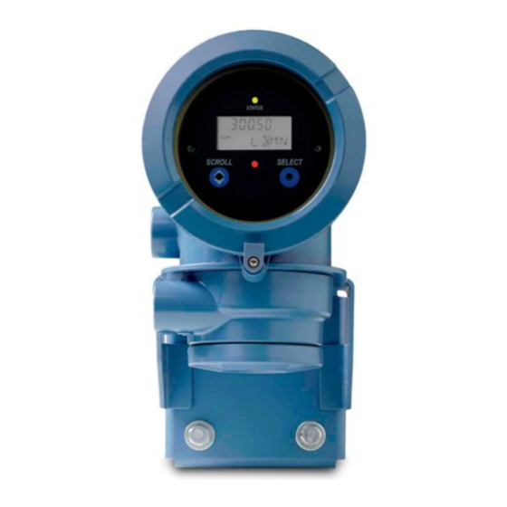
Transmitter operation Figure 8-1: Transmitter display features A. Status LED B. Display (LCD panel) C. Process variable D. Scroll optical switch E. Optical switch indicator: turns red when either Scroll or Select is activated F. Select optical switch G. Unit of measure for process variable H. -
Page 118: View Transmitter Status Using The Status Led
Transmitter operation • To view a more complete set of process variables, plus the current state of the outputs, choose Service Tools > Variables. View transmitter status using the status LED The status LED shows the current alert condition of the transmitter. The status LED is located on the face of the transmitter. -
Page 119: View And Acknowledge Status Alerts
Transmitter operation Table 8-1: Transmitter status reported by status LED (continued) LED state Description Recommendation Flashing red (if ena- One or more high-severity alerts are active A high-severity alert condition affects meas- bled) and have not been acknowledged. urement accuracy and output behavior. Re- solve the alert condition before continuing. - Page 120 Transmitter operation Figure 8-2: Using the display to view and acknowledge the status alerts Scroll and Select simultaneously for 4 seconds SEE ALARM Select Is ACK ALL enabled? ACK ALL Select Scroll EXIT Select Scroll Active/ unacknowledged alarms? Alarm code NO ALARM Scroll Select...
-
Page 121: View And Acknowledge Alerts Using Prolink Iii
Transmitter operation Postrequisites • To clear the following alerts, you must correct the problem, acknowledge the alert, then power-cycle the transmitter: A001, A002, A010, A011, A012, A013, A018, A019, A022, A023, A024, A025, A028, A029, A031. • For all other alerts: If the alert is inactive when it is acknowledged, it will be removed from the list. -
Page 122: View Alerts Using The Field Communicator
Transmitter operation 8.4.3 View alerts using the Field Communicator You can view a list containing all alerts that are active, or inactive but unacknowledged. • To view active or unacknowledged alerts, choose Service Tools > Alerts. All active alerts and unacknowledged alerts are listed. Note Only Fault and Informational alerts are listed. -
Page 123: Start And Stop Totalizers And Inventories Using The Display
Transmitter operation Overview When you start a totalizer, it tracks process measurement. In a typical application, its value increases with flow. When you stop a totalizer, it stops tracking process measurement and its value does not change with flow. Inventories are started and stopped automatically, when totalizers are started and stopped. -
Page 124: Reset Totalizers
Transmitter operation 3. Scroll until STOP appears beneath the current totalizer value. 4. Select. 5. Select again to confirm. 6. Scroll to EXIT. Reset totalizers Display Section 8.7.1. ProLink III Device Tools > Totalizer Control > Totalizer and Inventories > Reset Mass Total Device Tools >... - Page 125 Transmitter operation 2. Select. Exit displays beneath the current totalizer value. 3. Scroll until Reset displays beneath the current totalizer value. 4. Select. Reset and Yes? alternately flash beneath the current totalizer value. 5. Select again to confirm. 6. Scroll to EXIT. 7.
-
Page 126: Reset Inventories
Transmitter operation Reset inventories ProLink III Device Tools > Totalizer Control > Totalizer and Inventories > Reset Mass Inventory Device Tools > Totalizer Control > Totalizer and Inventories > Reset Volume Inventory Device Tools > Totalizer Control > Totalizer and Inventories > Reset Gas Inventory Device Tools >... -
Page 127: Chapter 9 Measurement Support
Measurement support Measurement support Topics covered in this chapter: • Options for measurement support • Use Smart Meter Verification (SMV) • Use PVR, TBR, and TMR • Piecewise linearization (PWL) for calibrating gas meters • Zero the meter • Validate the meter •... -
Page 128: Use Smart Meter Verification (Smv)
Measurement support Use Smart Meter Verification (SMV) You can run an SMV test, view and interpret the results, and set up automatic execution. 9.2.1 SMV requirements To use SMV, the transmitter must be paired with an enhanced core processor. Table 9‐1 for the minimum version of the transmitter, enhanced core processor, and communication tool needed to support SMV. -
Page 129: Run Smv
Measurement support SMV has an output mode called Continuous Measurement that allows the transmitter to keep measuring while the test is in progress. If you choose to run the test in Last Measured Value or Fault modes instead, the transmitter outputs will be held constant for the two minute duration of the test. - Page 130 Measurement support Option Description Last Value During the test, all outputs will report the last measured value of their as- signed process variable. The test will run for approximately 140 seconds. While the test is in progress, dots traverse the display and test progress is shown. Postrequisites View the test results and take any appropriate actions.
- Page 131 Measurement support SMV flowchart: Running a test using the display Figure 9-2: Running an SMV test using the display RUN VERFY Select OUTPUTS EXIT Scroll Select CONTINUE MEASR FAULT LAST VALUE EXIT Scroll Scroll Scroll Select Select Select ARE YOU SURE/YES? Select .
- Page 132 Measurement support You may need to wait a few seconds while ProLink III synchronizes its database with the transmitter data. Enter any desired information on the Test Definition screen, and click Next. All information on this screen is optional. Choose the desired output behavior. Option Description Continue Measur-...
-
Page 133: View Test Data
Measurement support Postrequisites View the test results and take any appropriate actions. 9.2.4 View test data You can view the results of the current test. You can also view results from previous tests. You must use ProLink III to view test results. Important You can view previous test results and see detailed test reports only if SMV is licensed. - Page 134 Measurement support Figure 9-3: SMV – Top-level menu Scroll and Select simultaneously for 4 seconds Scroll ENTER METER VERFY Select RUN VERFY RESULTS READ SCHEDULE VERFY EXIT Scroll Scroll Scroll Select Select Select Scroll Select b. Scroll to Results Read and press Select. The runcount of the most recent test is displayed.
- Page 135 Measurement support SMV flowchart: Viewing test results using the display Figure 9-4: Viewing SMV test results using the display RESULTS READ Select RUNCOUNT x Select Scroll Pass Result type Abort Fail xx HOURS xx HOURS xx HOURS Select Select Select PASS FAIL Abort Type...
- Page 136 Measurement support Procedure Choose Device Tools > Diagnostics > Meter Verification and click Previous Test Results. The chart shows test results for all tests stored in the ProLink III database. (Optional) Click Next to view and print a test report. (Optional) Click Export Data to CSV File to save the data to a file on your PC.
-
Page 137: Schedule Automatic Execution Of The Smv Test
Measurement support Table 9-3: SMV abort codes Code Description Recommended actions User-initiated abort None required. Wait 15 seconds before starting an- other test. Frequency drift Ensure that temperature, flow, and density are sta- ble, and rerun the test. High drive gain Ensure that flow is stable, minimize entrained gas, and rerun the test. - Page 138 Measurement support Figure 9-5: SMV – Top-level menu Scroll and Select simultaneously for 4 seconds Scroll ENTER METER VERFY Select RUN VERFY RESULTS READ SCHEDULE VERFY EXIT Scroll Scroll Scroll Select Select Select Scroll Select Scroll to Schedule Verfy and press Select. To schedule a single test or the first test in recurring execution: a.
- Page 139 Measurement support SMV flowchart: Scheduling test execution using the display Figure 9-6: Scheduling SMV test execution using the display SCHEDULE VERFY Select Schedule set? SCHED IS OFF TURN OFF SCHED/YES? Scroll Scroll Select Schedule deleted HOURS LEFT Scroll Select xx HOURS Select SET NEXT SET RECUR...
-
Page 140: Use Pvr, Tbr, And Tmr
Measurement support To schedule recurring execution, specify a value for Hours Between Recurring Runs. To disable scheduled execution: • To disable execution of a single scheduled test, set Hours Until Next Run to 0. • To disable recurring execution, set Hours Between Recurring Runs to 0. •... -
Page 141: Pvr, Tbr, And Tmr Applications
Measurement support 9.3.1 PVR, TBR, and TMR applications PVR, TBR, and TMR are applications designed to provide more accurate process data in the presence of multiple phases. For example, if bubbles are present in the process fluid, or the process fluid is flashing, the volume measurements are often incorrect. Production Volume Reconciliation (PVR) •... -
Page 142: Piecewise Linearization (Pwl) For Calibrating Gas Meters
PWL does not apply when measuring liquid flow. When better accuracy is required over the published gas measurement specifications, an Emerson-approved independent gas laboratory can calibrate gas up to 10 PWL adjustment points. -
Page 143: Validate The Meter
Measurement support • Verify that there is no flow through the sensor, then retry. • Remove or reduce sources of electromechanical noise, then retry. • Set Zero Time to a lower value, then retry. • If the zero continues to fail, contact customer service. Validate the meter Display OFF-LINE MAINT >... -
Page 144: Alternate Method For Calculating The Meter Factor For Volume Flow
Measurement support Obtain a reference device (external measurement device) for the appropriate process variable. Important For good results, the reference device must be highly accurate. Procedure Determine the meter factor as follows: a. Set the meter factor to 1 to take a sample measurement. b. -
Page 145: Perform A (Standard) D1 And D2 Density Calibration
Measurement support Procedure Calculate the meter factor for density, using the standard method (see Section 9.6). Calculate the meter factor for volume flow from the meter factor for density: MeterFactor Volume MeterFactor Density Note The following equation is mathematically equivalent to the first equation. You may use whichever version you prefer. -
Page 146: Perform A D1 And D2 Density Calibration Using Prolink Iii
Measurement support • If LD Optimization is enabled on your meter, disable it. To do this, choose Configure > Manual Setup > Measurements > LD Optimization. LD Optimization is used only with large sensors in hydrocarbon applications. In some installations, only customer service has access to this parameter. -
Page 147: Perform A D1 And D2 Density Calibration Using The Field Communicator
Measurement support Postrequisites If you disabled LD Optimization before the calibration procedure, re-enable it. 9.7.2 Perform a D1 and D2 density calibration using the Field Communicator Read the Prerequistes on page 137 if you have not already done so. See the following figure. Postrequisites If you disabled LD Optimization before the calibration procedure, re-enable it. -
Page 148: Perform A D3 And D4 Density Calibration (T-Series Sensors Only)
Measurement support Perform a D3 and D4 density calibration (T- Series sensors only) For T-Series sensors, the optional D3 and D4 calibration could improve the accuracy of the density measurement if the density of your process fluid is less than 0.8 g/cm or greater than 1.2 g/cm If you perform the D3 and D4 calibration, note the following:... -
Page 149: Perform A D3 Or D3 And D4 Density Calibration Using The Field Communicator
Measurement support Figure 9-7: D3 or D3 and D4 density calibration using ProLink III Close shutoff valve downstream from sensor D3 Calibration D4 Calibration Fill sensor with D3 fluid Fill sensor with D4 fluid Device Tools > Device Tools > Calibration >... -
Page 150: Perform Temperature Calibration
Measurement support Figure 9-8: D3 or D3 and D4 density calibration using the Field Communicator D3 Calibration D4 Calibration Close shutoff valve Fill sensor with D3 fluid Fill sensor with D4 fluid downstream from sensor On-Line Menu > Service Tools > Service Tools >... -
Page 151: Perform Temperature Calibration Using The Display
Measurement support Prerequisites The temperature calibration is a two-part procedure: temperature offset calibration and temperature slope calibration. The two parts must be performed without interruption, in the order shown. Ensure that you are prepared to complete the process without interruption. You will need a low-temperature calibration fluid and a high-temperature calibration fluid. - Page 152 Measurement support Temperature Offset Calibration Temperature Slope Calibration Fill sensor with Fill sensor with low-temperature fluid high-temperature fluid Wait until sensor achieves Wait until sensor achieves thermal equilibrium thermal equilibrium Device Tools > Device Tools > Calibration > Calibration > Temperature Calibration >...
-
Page 153: Perform Temperature Calibration Using The Field Communicator
Measurement support 9.9.3 Perform temperature calibration using the Field Communicator Temperature Offset calibration Temperature Slope calibration Fill sensor with low- Fill sensor with high- temperature fluid temperature fluid Wait until sensor achieves Wait until sensor achieves thermal equilibrium thermal equilibrium Service Tools >... - Page 154 Measurement support Micro Motion Model 1700 Transmitters with Analog Outputs...
-
Page 155: Chapter 10 Troubleshooting
Troubleshooting Troubleshooting Topics covered in this chapter: • Status LED states • Status alerts, causes, and recommendations • Flow measurement problems • Density measurement problems • Temperature measurement problems • Milliamp output problems • Frequency Output problems • Using sensor simulation for troubleshooting •... -
Page 156: Status Led States
Troubleshooting 10.1 Status LED states The status LED on the transmitter indicates whether or not alerts are active. If alerts are active, view the alert list to identify the alerts, then take appropriate action to correct the alert condition. Your transmitter has a status LED only if it has a display. If the transmitter has a display and LED Blinking is disabled, the status LED does not flash to indicate an unacknowledged alert. - Page 157 Troubleshooting Alert num- Alert title Possible cause Recommended actions A002 RAM Error (Core Pro- The core processor has experienced • Cycle power to the meter. cessor) a memory error. • Replace the core processor. • Contact customer support. A003 No Sensor Response The transmitter is not receiving one •...
- Page 158 Troubleshooting Alert num- Alert title Possible cause Recommended actions A008 Density Overrange The line density is greater than • If other alerts are present, resolve those 10 g/cm (10000 kg/m alert conditions first. If the current alert persists, continue with the recommen- ded actions.
- Page 159 Troubleshooting Alert num- Alert title Possible cause Recommended actions A011 Zero Calibration Many possible causes, such as too • Verify that there is no flow through the Failed: Low much flow, especially reverse flow, sensor, cycle power to the meter, then through the sensor during a calibra- retry the procedure.
- Page 160 Troubleshooting Alert num- Alert title Possible cause Recommended actions A017 Sensor Case Tem- The values computed for the resist- • Check your process conditions against perature (RTD) Fail- ance of the meter and case RTDs the values reported by the device. Tem- are outside limits.
- Page 161 Troubleshooting Alert num- Alert title Possible cause Recommended actions A020 Calibration Factors Some calibration factors have not • Verify all of the characterization or cali- Missing been entered or are incorrect. bration parameters. See the sensor tag or the calibration sheet for your meter. •...
- Page 162 Troubleshooting Alert num- Alert title Possible cause Recommended actions A026 Sensor/Transmitter The transmitter has lost communi- • Check the wiring between the sensor Communications cation with the core processor. and the transmitter. Failure There may be a problem with the •...
- Page 163 Troubleshooting Alert num- Alert title Possible cause Recommended actions A033 Insufficient Pickoff The signal from the sensor pick- • Check for air in the flow tubes, tubes Signal off(s) is insufficient. This suggests not filled, foreign material in the tubes, that the sensor tubes or vibrating coating in the tubes, or other process elements are not vibrating.
- Page 164 Troubleshooting Alert num- Alert title Possible cause Recommended actions A102 Drive Overrange The drive power (current/voltage) is • Check the drive gain and the pickoff at its maximum. voltage. • Check the wiring between the sensor and the transmitter. • Verify that internal wiring is secure and that there are no internal electrical problems.
- Page 165 Troubleshooting Alert num- Alert title Possible cause Recommended actions A108 Basic Event 1 On The process has triggered Basic • No action required. Event 1. • Review event configuration if you be- lieve the event was triggered errone- ously. A109 Basic Event 2 On The process has triggered Basic •...
- Page 166 Troubleshooting Alert num- Alert title Possible cause Recommended actions A114 mA Output 2 Fixed The mA Output is configured to • Check whether the output is in loop test send a constant value. mode. If it is, unfix the output. •...
-
Page 167: Flow Measurement Problems
Troubleshooting 10.3 Flow measurement problems Problem Possible causes Recommended actions Non-zero flow reading • Misaligned piping (especially in new instal- • If the reading is not excessively high, re- at no-flow conditions lations) view the live zero. You may need to restore or at zero offset •... - Page 168 Troubleshooting Problem Possible causes Recommended actions Erratic non-zero flow • Two-phase flow • Verify that the sensor orientation is appro- rate when flow is • Damping value too low priate for your application (refer to the steady • Plugged or coated sensor tube sensor installation manual).
-
Page 169: Density Measurement Problems
Troubleshooting 10.4 Density measurement problems Problem Possible causes Recommended actions Inaccurate density • Problem with process fluid • Check your process conditions against the reading • Incorrect density calibration factors values reported by the device. • Wiring problem • Ensure that all of the calibration parame- •... -
Page 170: Temperature Measurement Problems
Troubleshooting 10.5 Temperature measurement problems Problem Possible causes Recommended actions Temperature reading • RTD failure • Check junction box for moisture or verdi- significantly different • Incorrect compensation factors gris. from process temper- • Line temperature in bypass does not •... -
Page 171: Milliamp Output Problems
Troubleshooting 10.6 Milliamp output problems Table 10-2: Milliamp output problems and recommended actions Problem Possible causes Recommended actions No mA Output • Wiring problem • Check the power supply and power supply • Circuit failure wiring. • Channel not configured for desired output •... -
Page 172: Frequency Output Problems
Troubleshooting Table 10-2: Milliamp output problems and recommended actions (continued) Problem Possible causes Recommended actions Consistently incorrect • Loop problem • Check the mA Output trim. mA measurement • Output not trimmed correctly • Verify that the measurement units are con- •... -
Page 173: Using Sensor Simulation For Troubleshooting
Troubleshooting 10.8 Using sensor simulation for troubleshooting When sensor simulation is enabled, the transmitter reports user-specified values for basic process variables. This allows you to reproduce various process conditions or to test the system. You can use sensor simulation to help distinguish between legitimate process noise and externally caused variation. -
Page 174: Check Sensor-To-Transmitter Wiring
Troubleshooting Ensure that the power supply wires are connected to the correct terminals. Ensure that the power supply wires are making good contact, and are not clamped to the wire insulation. Inspect the voltage label inside the wiring compartment. The voltage supplied to the transmitter should match the voltage specified on the label. -
Page 175: Check Grounding
Troubleshooting Verify that the wires are making good contact with the terminals. Check the continuity of all wires from the transmitter to the sensor. 10.11 Check grounding A sensor and the transmitter must be grounded. If the core processor is installed as part of the transmitter or the sensor, it is grounded automatically. - Page 176 Troubleshooting b. Read the mA current at the receiving device and compare it to the transmitter output. The readings do not need to match exactly. If the values are slightly different, you can correct the discrepancy by trimming the output. c.
-
Page 177: Perform Loop Tests Using Prolink Iii
Troubleshooting Postrequisites • If the mA Output readings are within 20 microamps of the expected values, you can correct this discrepancy by trimming the output. • If the discrepancy between the mA Output readings is greater than 20 microamps, or if at any step the reading was faulty, verify the wiring between the transmitter and the remote device, and try again. -
Page 178: Perform Loop Tests Using The Field Communicator
Troubleshooting e. Click UnFix FO. Test the Discrete Output(s). a. Choose Device Tools > Diagnostics > Testing > Discrete Output Test. b. Set Fix To: to ON. c. Verify the signal at the receiving device. d. Set Fix To: to OFF. e. -
Page 179: Check The Hart Communication Loop
Troubleshooting g. Choose End. Test the Frequency Output(s). Note If the Weights & Measures application with NTEP approval is enabled on the transmitter, it is not possible to perform a loop test of the Frequency Output, even when the transmitter is unsecured. -
Page 180: Check Hart Address And Ma Output Action
Troubleshooting • Optional: the HART Application Guide, available at www.hartcomm.org Procedure Verify that the loop wires are connected as shown in the wiring diagrams in the transmitter installation manual. If your HART network is more complex than the wiring diagrams in the transmitter installation manual, contact either customer service or the HART Communication Foundation. -
Page 181: Check Hart Burst Mode
Troubleshooting 10.15 Check HART burst mode HART burst mode is normally disabled, and should be enabled only if a HART Triloop is being used. Check to see if burst mode is enabled or disabled. If burst mode is enabled, disable it. 10.16 Check the trimming of the mA Output If the trim values for the mA Output are inaccurate, the transmitter will under-compensate... -
Page 182: Check For Radio Frequency Interference (Rfi)
Troubleshooting 10.19 Check for radio frequency interference (RFI) The transmitter's Frequency Output or Discrete Output can be affected by radio frequency interference (RFI). Possible sources of RFI include a source of radio emissions, or a large transformer, pump, or motor that can generate a strong electromagnetic field. Several methods to reduce RFI are available. -
Page 183: Check Flow Direction
Troubleshooting 10.22 Check Flow Direction If Flow Direction is set inappropriately for your process, the transmitter may report flow data that is not appropriate for your requirements. The Flow Direction parameter interacts with actual flow direction to affect flow values, flow totals and inventories, and output behavior. -
Page 184: Check The Drive Gain
Troubleshooting You can reduce the occurrence of two-phase flow alerts by setting Two-Phase Flow Low Limit to a lower value, Two-Phase Flow High Limit to a higher value, or Two-Phase Flow Timeout to a higher value. Micro Motion recommends leaving the Two-Phase Flow High Limit at the default value. -
Page 185: Collect Drive Gain Data
Troubleshooting Table 10-4: Possible causes and recommended actions for excessive (saturated) drive gain (continued) Possible cause Recommended actions Sensor imbalance Contact customer support. Sensor tubes Correct process conditions so that the sensor tubes are full. not completely full Two-phase flow Check for two-phase flow. -
Page 186: Collect Pickoff Voltage Data
Troubleshooting Table 10-6: Possible causes and recommended actions for low pickoff voltage Possible cause Recommended actions Cavitation or flashing; settling • Increase the inlet or back pressure at the sensor. Increasing of two-phase or three-phase back pressure is recommended. Applying back pressure down- fluids stream from the sensor can prevent flashing inside the sensor tubes. -
Page 187: Check The Sensor Coils
Troubleshooting Possible cause Recommended action Moisture inside the sensor junction Ensure that the junction box is dry and no corrosion is present. Liquid or moisture inside the sensor Contact customer support. case Internally shorted feedthrough Contact customer support. Faulty cable Replace the cable. - Page 188 Troubleshooting Table 10-7: Coils and test terminal pairs (continued) Coil Sensor model Terminal colors Composite RTD All CMFSs, T-Series, H300, and Yellow to orange F300 Fixed resistor (see note) CMFS007, CMFS010, CMFS015, Yellow to orange CMF400, and F300 Note The F300/H300/CMF400 fixed resistor applies to only certain specific sensor releases. Contact customer support for more information.
-
Page 189: Check The Core Processor Led
Troubleshooting There should be infinite resistance for each pair. If there is any resistance at all, there is a short between terminals. Postrequisites To return to normal operation: Plug the terminal blocks into the terminal board. Replace the end-cap on the core processor housing. Replace the lid on the sensor junction box. - Page 190 Troubleshooting Figure 10-1: Integral installation components A. Transmitter B. Transition ring C. 4 x cap screws (4 mm) D. Base E. Core processor b. Rotate the transmitter counter-clockwise so that the cap screws are in the unlocked position. c. Gently lift the transmitter straight up, disengaging it from the cap screws. Important Do not disconnect or damage the wires that connect the transmitter to the core processor.
- Page 191 Troubleshooting Figure 10-2: 9-wire remote installation components A. Transmitter B. Core processor C. 4 x cap screws (4 mm) D. End cap b. Inside the core processor housing, loosen the three screws that hold the core processor mounting plate in place. Do not remove the screws.
-
Page 192: Core Processor Led States
Troubleshooting Postrequisites To return to normal operation: • For a 4-wire remote installation or a remote core processor with remote transmitter installation, replace the core processor lid. • For an integral installation: 1. Without pinching or stretching the wires, lower the transmitter onto the base, inserting the cap screws into the slots. - Page 193 Troubleshooting Table 10-8: Standard core processor LED states (continued) LED state Description Recommended actions Core processor receiving less • Verify power supply wiring to core processor. than 5 volts • If transmitter status LED is lit, transmitter is re- ceiving power. Check voltage across terminals 1 (VDC+) and 2 (VDC–) in core processor.
-
Page 194: Perform A 700 Core Processor Resistance Test
Troubleshooting Table 10-9: Enhanced core processor LED states (continued) LED state Description Recommended action Core processor internal failure The meter requires factory service. 10.29 Perform a 700 core processor resistance test Note You can perform a resistance test only on a 700 core processor. Procedure Power down the transmitter. - Page 195 Troubleshooting c. Gently lift the transmitter straight up, disengaging it from the cap screws. If you have a 9-wire remote installation: a. Remove the end-cap. Figure 10-3: 9-wire remote installation components A. Transmitter B. Core processor C. 4 x cap screws (4 mm) D.
- Page 196 Troubleshooting Measure the resistance between core processor terminal pairs 3–4, 2–3, and 2–4. Terminal pair Function Expected resistance 3–4 RS-485/A and RS-485/B 40 kΩ to 50 kΩ 2–3 VDC– and RS-485/A 20 kΩ to 25 kΩ 2–4 VDC– and RS-485/B 20 kΩ...
-
Page 197: Appendix A Using The Transmitter Display
Using the transmitter display Appendix A Using the transmitter display Topics covered in this appendix: • Components of the transmitter interface • Use the optical switches • Access and use the display menu system • Display codes for process variables •... -
Page 198: Use The Optical Switches
Using the transmitter display Figure A-1: Transmitter interface Status LED Display (LCD panel) Process variable Scroll optical switch Optical switch indicator Select optical switch Unit of measure for process variable Current value of process variable Use the optical switches Use the optical switches on the transmitter interface to control the transmitter display. The transmitter has two optical switches: Scroll and Select. -
Page 199: Access And Use The Display Menu System
Using the transmitter display Table A-1: Optical switch indicator and optical switch states Optical switch indicator State of optical switches Solid red One optical switch is activated. Flickering red Both optical switches are activated. Access and use the display menu system The display menu system is used to perform various configuration, administrative, and maintenance tasks. -
Page 200: Enter A Floating-Point Value Using The Display
Using the transmitter display Use the Scroll and Select optical switches to navigate to your destination in the display menu system. • Use Scroll to move through a list of options. • Use Select to choose the current option. If Scroll flashes on the display, activate the Scroll optical switch, then the Select optical switch, and then the Scroll optical switch again. - Page 201 Using the transmitter display Procedure • To change the value: 1. Activate Select until the digit you want to change is active (flashing). Select moves the cursor one position to the left. From the leftmost position, Select moves the cursor to the rightmost digit. 2.
- Page 202 Using the transmitter display If the displayed value is the same as the value in transmitter memory, you will be returned to the previous screen. If the displayed value is not the same as the value in transmitter memory, SAVE/ YES? flashes on the display.
-
Page 203: Display Codes For Process Variables
Using the transmitter display d. Activate Scroll until the desired character is displayed. e. Activate Select to move the cursor one digit to the left. f. Activate Scroll until the desired character is displayed. g. Activate Select to move the cursor one digit to the left. h. -
Page 204: Codes And Abbreviations Used In Display Menus
Using the transmitter display Table A-2: Display codes for process variables (continued) Code Definition Comment or reference LVOLI Volume inventory LZERO Live zero flow MASSI Mass inventory MTR_T Case temperature (T-Series sensors only) NET M Net mass flow rate Concentration measurement application only NET V Net volume flow rate Concentration measurement application only... - Page 205 Using the transmitter display Table A-3: Codes and abbreviations used in display menus (continued) Code or abbrevia- tion Definition Comment or reference Analog output 2 (secondary mA Output) AUTO SCRLL Auto Scroll BKLT Backlight B LIGHT Calibrate CH A Channel A CHANGE PASSW Change password Change the password or passcode required for...
- Page 206 Using the transmitter display Table A-3: Codes and abbreviations used in display menus (continued) Code or abbrevia- tion Definition Comment or reference EXTRN External FAC Z Factory zero Flow calibration factor FLDIR Flow direction FL SW Flow switch FLSWT Frequency Output FO FREQ Frequency factor FO RATE...
- Page 207 Using the transmitter display Table A-3: Codes and abbreviations used in display menus (continued) Code or abbrevia- tion Definition Comment or reference QUAD Quadrature Revision SCALE Scaling method SFM60 Shrinkage factor PVR applications only corrected volume of mix at 60F SFO60 Shrinkage Fac Corr PVR applications only...
- Page 208 Using the transmitter display Micro Motion Model 1700 Transmitters with Analog Outputs...
-
Page 209: Appendix B Using Prolink Iii With The Transmitter
In most ProLink III installations, the manual is installed with the ProLink III program. Additionally, the ProLink III manual is available on the documentation CD or at www.emerson.com. ProLink III features and functions ProLink III offers complete transmitter configuration and operation functions. ProLink III also offers a number of additional features and functions, including: •... -
Page 210: Connect With Prolink Iii
Using ProLink III with the transmitter • The ability to connect to and view information for more than one device • A guided connection wizard These features are documented in the ProLink III manual. They are not documented in the current manual. -
Page 211: Connect With Prolink Iii To The Service Port
Using ProLink III with the transmitter • You cannot make concurrent Modbus connections if the connections use the same terminals. You can make concurrent Modbus connections if the connections use different terminals. B.2.2 Connect with ProLink III to the service port CAUTION! If the transmitter is in a hazardous area, do not use a service port connection. -
Page 212: Make A Hart/Bell 202 Connection
Using ProLink III with the transmitter Figure B-1: Connection to service port A. PC B. Signal converter C. Service port terminal 7 (RS‐485/A) D. Service port terminal 8 (RS‐485/B) E. Transmitter, with wiring compartment and power supply compartment opened Note This figure shows a serial port connection. - Page 213 Using ProLink III with the transmitter CAUTION! If the transmitter is in a hazardous area, do not connect directly to the transmitter terminals. Connecting directly to the transmitter terminals requires opening the wiring compartment, and opening the wiring compartment while the transmitter is powered up could cause an explosion.
- Page 214 Using ProLink III with the transmitter Figure B-2: Connection to transmitter terminals A. Computer B. Signal converter C. Transmitter Note This figure shows a serial port connection. USB connections are also supported. To connect to a point in the local HART loop: a.
- Page 215 Using ProLink III with the transmitter Figure B-3: Connection over local loop A. PC B. Signal converter C. Any combination of resistors R1, R2, and R3 as necessary to meet HART communication resistance requirements D. DCS or PLC E. Transmitter, with wiring compartment and power supply compartment opened Note This figure shows a serial port connection.
- Page 216 Using ProLink III with the transmitter Figure B-4: Connection over multidrop network A. Signal converter Ω resistance B. 250–600 C. Devices on the network D. Master device Start ProLink III. Choose Connect to Physical Device. Set Protocol to HART Bell 202. HART/Bell 202 connections use standard connection parameters.
-
Page 217: Make A Hart/Rs-485 Connection
Using ProLink III with the transmitter Option Description Primary Use this setting if no other primary host is on the network. The Field Communicator is a secondary host. Click Connect. Need help? If an error message appears: • Verify the HART address of the transmitter, or poll HART addresses 1–15. •... - Page 218 Using ProLink III with the transmitter HART connections are not polarity-sensitive, but RS-485 connections are. Figure B-5: Connection to transmitter terminals A. PC B. Signal converter C. Transmitter, with wiring compartment and power supply compartment opened Note This figure shows a serial port connection. USB connections are also supported. To connect over the RS-485 network: a.
- Page 219 Using ProLink III with the transmitter Figure B-6: Connection over network A. PC B. Adapter, if necessary C. Signal converter Ω , 1/2‐watt resistors at both ends of the segment, if necessary for noise suppression D. 120- E. DCS or PLC F.
-
Page 220: Connect With Prolink Iii To The Rs-485 Port
Using ProLink III with the transmitter Set Master as appropriate. Option Description Secondary Use this setting if a primary HART host such as a DCS is on the network. Primary Use this setting if no other primary host is on the network. The Field Communicator is a secondary host. - Page 221 Using ProLink III with the transmitter a. Remove the transmitter end-cap to access the wiring compartment. b. Connect the leads from the signal converter to terminals 5 (RS-485/A) and 6 (RS-485/B). Usually, but not always, the black lead is RS-485/A and the red lead is RS-485/B. Figure B-7: Connection to transmitter terminals A.
- Page 222 Using ProLink III with the transmitter Figure B-8: Connection over network A. Computer B. Signal converter Ω , 1/2‐watt resistors at both ends of the segment, if necessary for noise suppression C. 120- D. DCS or PLC E. Transmitter, with wiring compartment and power supply compartment opened Note This figure shows a serial port connection.
- Page 223 Using ProLink III with the transmitter Select Connect. Need help? If an error message appears: • Verify the Modbus address of the transmitter. • Ensure that you have specified the correct port on your PC. • Check the wiring between the PC and the transmitter. •...
- Page 224 Using ProLink III with the transmitter Micro Motion Model 1700 Transmitters with Analog Outputs...
-
Page 225: Appendix C Using A Field Communicator With The Transmitter
If you are unable to perform these tasks, consult the Field Communicator manual before attempting to use the Field Communicator. The Field Communicator manual is available on the documentation CD or at www.emerson.com. Device descriptions (DDs) In order for the Field Communicator to work with your device, the appropriate device... -
Page 226: Connect With The Field Communicator
Using a Field Communicator with the transmitter Field Communicator menus and messages Many of the menus in this manual start with the On-Line menu. Ensure that you are able to navigate to the On-Line menu. As you use the Field Communicator with a Micro Motion transmitter, you will see a number of messages and notes. - Page 227 Using a Field Communicator with the transmitter Figure C-1: Field Communicator connection to transmitter terminals A. Field Communicator Ω resistance B. 250–600 C. Transmitter, with wiring compartment and power supply compartment opened To connect to a point in the local HART loop, attach the leads from the Field Communicator to any point in the loop and add resistance as necessary.
- Page 228 Using a Field Communicator with the transmitter Figure C-3: Field Communicator connection to multidrop network A. Field Communicator Ω resistance B. 250–600 C. Devices on the network D. Master device Turn on the Field Communicator and wait until the main menu is displayed. If you are connecting across a multidrop network: •...
-
Page 229: Appendix D Default Values And Ranges
Default values and ranges Appendix D Default values and ranges Default values and ranges The default values and ranges represent the typical factory transmitter configuration. Depending on how the transmitter was ordered, certain values may have been configured at the factory and are not represented in the default values and ranges. Table D-1: Transmitter default values and ranges Type... - Page 230 Default values and ranges Table D-1: Transmitter default values and ranges (continued) Type Parameter Default Range Comments Volume factor Density Density damping 1.6 sec 0.0 – 51.2 sec User-entered value is corrected to nearest valid value in a list of preset values.
- Page 231 Default values and ranges Table D-1: Transmitter default values and ranges (continued) Type Parameter Default Range Comments Special units Base mass unit Base mass time Mass flow conversion factor Base volume unit Base volume time Volume flow conversion factor Variable map- Primary variable Mass flow ping...
- Page 232 Default values and ranges Table D-1: Transmitter default values and ranges (continued) Type Parameter Default Range Comments 0.00 g/cm Read-only. LSL is calculated based on the sensor size and characterization parameters. 10.00 g/cm Read only. USL is calculated based on the sensor size and characterization parameters.
- Page 233 Default values and ranges Table D-1: Transmitter default values and ranges (continued) Type Parameter Default Range Comments Frequency Output polarity Active high Last measured value timeout 0.0 seconds 0.0 – 60.0 sec Discrete Out- Source Flow direction Fault Indicator None Power Internal Polarity...
- Page 234 Default values and ranges Micro Motion Model 1700 Transmitters with Analog Outputs...
-
Page 235: Appendix E Transmitter Components And Installation Wiring
Transmitter components and installation wiring Appendix E Transmitter components and installation wiring Topics covered in this appendix: • Installation types • Power supply terminals and ground • Input/output (I/O) wiring terminals Installation types The transmitter was ordered and shipped to be installed in one of several possible configurations. - Page 236 Transmitter components and installation wiring Figure E-2: High-temperature meters with factory connection The transmitter is shipped with a flexible connection factory installed between the sensor and the transmitter. The transmitter must be dismounted from its shipping location (spot‐welded to the sensor case) and then mounted separately.
- Page 237 Transmitter components and installation wiring Figure E-4: Remote core processor with remote sensor installation The transmitter, core processor, and sensor are all mounted separately. The 4‐wire connection between the transmitter and core processor must be field wired. The 9‐wire connection between the core processor and the sensor must be field wired.
-
Page 238: Power Supply Terminals And Ground
Transmitter components and installation wiring Power supply terminals and ground Figure E-5: Power supply wiring terminals Warning flap Equipment ground Power supply wiring terminals (9 and 10) Micro Motion Model 1700 Transmitters with Analog Outputs... -
Page 239: Input/Output (I/O) Wiring Terminals
Transmitter components and installation wiring Input/output (I/O) wiring terminals Figure E-6: I/O wiring terminals mA/HART Frequency Output or Discrete Output RS‐485 Configuration and Use Manual... - Page 240 Transmitter components and installation wiring Micro Motion Model 1700 Transmitters with Analog Outputs...
-
Page 241: Appendix F Ne 53 History
NE 53 history Appendix F NE 53 history NE 53 history Important Not all features and capabilities described in this section may apply to your transmitter or configuration. August 2000, Version 1.x Modification type Change Expansion Added writing of the device tag using Modbus Adjustment Improved communication handling with the HART Tri-Loop prod- Feature... - Page 242 NE 53 history December 2001, version 3.x Modification type Change Expansion • Added support for the configurable I/O option board • Software version information available via the display or Modbus • Configurable density cutoff • Additional HART variables can be assigned to QV •...
- Page 243 NE 53 history September 2006, version 5.x Modification type Change Expansion • Discrete Output assignable as a flow switch • Discrete Output fault indication configurability • Discrete Input support for multiple action assignments • Added support for querying the display LED status via Mod- •...
- Page 244 NE 53 history Modification type Change Feature • Configurable hysteresis for flow switch • Field Verification Zero added to support Weights & Measures application • Transmitter firmware checksum and core processor firmware checksum assignable as display variables and viewable in Pro- Link February 2018, version 8.x Modification type...
- Page 245 NE 53 history Modification type Change Adjustment • Sensors that are not straight tube sensors are now correctly identified • The mA Output fixed alert is now set • The Factory Configuration Invalid status bit is now set cor- rectly when connected to a 700 core processor — as the 700 core processor does not support saving and restoring the fac- tory configuration •...
- Page 246 NE 53 history Modification type Change An AMS Field Device did not respond message no longer displays when the concentration offset is con- figured even though the value was changed When the volume flow type is changed, the new setting is updated from the transmitter without having to rescan the device Feature...
- Page 247 NE 53 history Configuration and Use Manual...
- Page 248 © 2018 Micro Motion, Inc. All rights reserved. The Emerson logo is a trademark and service mark of Emerson Electric Co. Micro Motion, ELITE, ProLink, MVD and MVD Direct Connect marks are marks of one of the Emerson Automation Solutions family of companies. All other marks are property of their respective owners.