Table of Contents
Advertisement
Quick Links
INSTALLATION AND MAINTENANCE INSTRUCTIONS
SK-Beam, SK-Beam-T
Single-ended Reflected Type
Projected Beam Smoke Detector
SPECIFICATIONS
GENERAL
Range:
Sensitivity:
Spacing:
Response Time:
Trouble Conditions:
Test/Reset Features:
Indicators:
Style 7 Operation:
ENVIRONMENTAL
Temperature:
Humidity:
Mechanical
Shipping Weight:
Shipping Size:
Mounting:
Wiring:
Adjustment Angle:
Paintable Trim Ring:
Electrical
Voltage:
Standby Current:
External Supply (SK-Beam-T only):
Remote Output: (alarm)
GENERAL DESCRIPTION
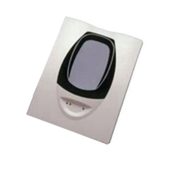
Model SK-Beam/SK-Beam-T is a long range projected beam smoke detector
designed to provide open area protection. It is to be used with UL-listed com-
patible control panels only. The detector consists of a transmitter/receiver unit
and a reflector. Smoke entering the area between the transmitter/receiver and
reflector causes a reduction in signal. When the obscuration reaches alarm
thresholds (chosen at the transmitter/receiver unit), the detector generates
an alarm signal. Complete blockage of the beam causes a trouble signal. Slow
changes in obscuration due to a build up of dirt or dust on the lens of the
detector are compensated for by a microcontroller that continuously monitors
16 to 230 Feet (5 to 70 m); 230 to 328 Feet (70 to 100 m) using optional accessory BEAMLRK
25% to 50% Total Obscuration in 6 levels
Level 1 = 25%
Level 2 = 30%
Level 3 = 40%
Level 4 = 50%
Level 5 = 30% to 50% (Acclimate)
Level 6 = 40% to 50% (Acclimate)
30 to 60 Feet (9.1 to 18.3 m)
ALARM - 20 seconds typical
TROUBLE - 30 seconds typical
Beam Blockage (96% or More Obscuration)
Improper Initial Alignment
Self-compensation limit reached (service needed)
In Alignment mode
Integral Sensitivity Test Filter (SK-Beam-T only, requires additional external power supply)
Sensitivity Filter (Incremental scale on reflector)
Local Alarm Test Switch
Local Alarm Reset Switch
Remote Test and Reset Switch Capability (compatible with RTS451/RTS451KEY/RTS151/RTS151KEY)
ALARM - Remote Output, Local LED (red)
TROUBLE - Remote Output, Local LED (yellow) Blink Pattern Indicates Trouble Diagnostics
NORMAL OPERATION - Local LED (flashing green with communication)
ALIGNMENT AIDS - Optical Gunsight (coarse adjustment) 00 to 99 Digital Display (fine adjustment)
SENSITIVITY - Digital Display Readout in Percent Obscuration
On-board isolators provide style 7 operation. (may be disabled via shunts on circuit board)
–22°F to 131°F (–30°C to 55°C);
NOTE: for applications below 32°F (0°C) see Special Applications section of this manual.
10% to 93% RH Noncondensing
3.9 lbs. (1.77 kg)
15˝ × 10.5˝ × 6.5˝ (381 mm × 267 mm × 165 mm)
Wall only without optional accessories
Plug-in Terminal Blocks (12 to 22 AWG)
±10° Horizontal and Vertical
May be painted using enamel or acrylic type paints
15 to 32 VDC
Avg. Standby:
Max. Alarm (LED on):
Max. Trouble (LED on):
Max. Alignment:
VOLTAGE - 15 to 32 VDC
CURRENT - 0.5 A Max.
VOLTAGE - 15 to 32 VDC; NOTE: Output voltage same as device input voltage.
CURRENT - 15 mA maximum; 6 mA minimum; NOTE: Output current is limited by 2.2 kΩ resistor.
2 mA Max. (1 communication every 5 sec., LED flashing, SLC @ 24 V)
8.5 mA Max.
4.5 mA Max.
20 mA Max.
the signal strength and periodically updates the alarm and trouble thresh-
olds. When the self-compensation circuit reaches its limit, the detector gen-
erates a trouble signal, indicating the need for service.
Three LEDs on the detector indicate the current status: a red LED for alarm,
a yellow LED for trouble, and a blinking green LED for standby operation.
Note: The panel controls the status of the red and green LEDs. The local
reset button is accessible by removing the outer paintable trim ring. The
yellow LED will blink in specific patterns to provide a diagnostic aid when
diagnosing the cause of a trouble signal. It will also blink the amount of drift
compensation that has been used at the conclusion of the test. Trouble sig-
1
12 Clintonville Road, Northford, CT 06472-1610
Phone: 203-484-7161 Fax: 203-484-7118
www.silentknight.com
I56-3433-004
04-12
Advertisement
Table of Contents

Related Manuals for Honeywell SK-Beam


Summary of Contents for Honeywell SK-Beam
- Page 1 Improper Initial Alignment Self-compensation limit reached (service needed) In Alignment mode Test/Reset Features: Integral Sensitivity Test Filter (SK-Beam-T only, requires additional external power supply) Sensitivity Filter (Incremental scale on reflector) Local Alarm Test Switch Local Alarm Reset Switch Remote Test and Reset Switch Capability (compatible with RTS451/RTS451KEY/RTS151/RTS151KEY)
- Page 2 BEAMHK nals automatically reset upon removing the cause of trouble. Red and yellow LEDs can be remotely connected to the remote Alarm and Trouble outputs. The BEAMHK allows the transmitter/receiver unit to operate in environments These outputs mimic the functions of the detector’s red and yellow LEDs. prone to the formation of condensation.
-
Page 3: Mounting Locations
FIGURE 3. SLOPED CEILING (SHED TYPE): In a room with a smooth ceiling, detectors should be spaced between 30 and 60 feet (9.1 to 18.3 m). One-half that spacing between the beam and the side- 3 F T . ( 0 . 9 M wall may be used as a guide. -
Page 4: Wiring Installation Guidelines
line of sight to the transmitter/receiver unit. The maximum tolerance for non- detector will not be able to distinguish these reflections from those of the re- perpendicular mounting locations is 10°. See Figure 5b. If the reflector cannot flector and the protected space will be compromised. be mounted within 10°... -
Page 5: Installation / Alignment
FIGURE 6. WIRING CONNECTIONS AT DETECTOR FIGURE 8. WIRING DIAGRAM (RTS451/RTS151) DETECTOR T1-1 SLC IN + SLC OUT + T1-3 PIN 1 T1-2 SLC IN – SLC OUT – T1-4 PIN 2 T2-1 REMOTE ALARM OUT PIN 4 T2-2 AUX (–) T2-4 RESET INPUT PIN 3... -
Page 6: Step 1. Coarse Alignment
STEP 1. COARSE ALIGNMENT FIGURE 10. SWITCH LOCATIONS Refer to Figures 11 and 12 for this step. Ensure that both optics lock-down screws are loose (Figure 11). Look through the alignment mirror and find the reflector (Figure 12). If it is difficult to spot, use the orange adhesive-backed paper installed with the reflector as a reference. - Page 7 40 to 50 80 to 220 24.4 to 67 nance. The sensitivity of the SK-Beam/SK-Beam-T may be tested as follows: Level 2 NOTE: Before testing the detector, check for the presence of the flashing green In addition to the four standard sensitivity selections the detector has two Ac- LED at the receiver, making sure not to disturb or block the beam.
-
Page 8: Maintenance
NOTE: For the SK-Beam this test does not satisfy the requirements of NFPA72 for periodic maintenance and sensitivity verification of beam type detectors. For the SK-Beam-T this test in conjunction with the complete reflector block-... -
Page 9: Appendix I. Operation Modes And Troubleshooting Guide
Blink Depressing RESET switch after alignment exit complete alignment Local Test Blinking Panel or RTS451, RTS451KEY, Remains in alarm until reset or time-out (SK-Beam-T) RTS151, or RTS151KEY Pass Result amount of drift used Local Test On until Blink Blink Panel or RTS451, RTS451KEY,... - Page 10 I56-3433-004 04-12...
-
Page 11: Appendix Ii. Detector Drilling Template
APPENDIX II. DETECTOR DRILLING TEMPLATE 6.190˝ (157 mm) 4.345˝ (110 mm) Scale = 1:1 C0278-00 I56-3433-004 04-12... - Page 12 I56-3433-004 04-12...
-
Page 13: Appendix Iii. Reflector Drilling Template
APPENDIX III. REFLECTOR DRILLING TEMPLATE 5.512˝ (140mm) 8.465˝ (215mm) Scale = 1:1 C0279-00 I56-3433-004 04-12... -
Page 14: Fcc Statement
This equipment generates, uses, and Silent Knight ® and Honeywell ® are registered trademarks of Honeywell International, Inc. I56-3433-004 ©2017 Honeywell. 04-12...