Alcatel OMNIPCX OFFICE Technical Documentation Manual
Hide thumbs
Also See for OMNIPCX OFFICE:
- User manual (63 pages) ,
- Technical communication (27 pages) ,
- Manual (16 pages)
Advertisement
Table of Contents
- 1 Main Features
- 2 General Description
- 3 Hardware Requirements
- 4 Answering a Call
- 5 Making a Call
- 6 System Limits
- 7 System Features
- 8 Automated Attendant
- 9 User Interfaces
- 10 Available Features
- 11 General Operation
- 12 Installation Guide
- 13 Internet Access
- 14 Operating Mode
- 15 Downloading the Software
- Download this manual
Advertisement
Table of Contents

Related Manuals for Alcatel OMNIPCX OFFICE


Summary of Contents for Alcatel OMNIPCX OFFICE
- Page 1 ALCATEL OMNIPCX OFFICE TECHNICAL DOCUMENTATION REF3EH 21000 BSAA Ed. 04...
- Page 3 SOFTWARE KEYS Section REF3EH 21000 BSAA Ed. 04 MAINTENANCE Copyright © ALCATEL. 2001. All rights reserved. Alcatel Business Systems, in keeping with its policy of constant product improvement for Section the customer, reserves the right to modify product specifications without prior notice.
- Page 5 Alcatel OmniPCX Office GENERAL INDEX REF3EH 21000 BSAA Ed. 04...
- Page 7 AOCC (Alcatel Office Call Center) ....... . APPLI File 4...
- Page 8 ALCATEL OMNIPCX OFFICE GENERAL INDEX ARS (internal destinations)........PRIVNET File 2 ARS (overview) .
- Page 9 ALCATEL OMNIPCX OFFICE GENERAL INDEX Collective Speed Dial ......... . FEATURES File 22 Complementary services (cost) .
- Page 10 ALCATEL OMNIPCX OFFICE GENERAL INDEX Enquiry call ..........FEATURES File 26 Euro (call metering) .
- Page 11 ALCATEL OMNIPCX OFFICE GENERAL INDEX Importing/exporting files ........PM5 File 1 Initializing mailboxes .
- Page 12 ALCATEL OMNIPCX OFFICE GENERAL INDEX MMC Station password......... MMC File 1 Mobile Reflexes (implementation) .
- Page 13 ALCATEL OMNIPCX OFFICE GENERAL INDEX Protecting calls..........FEATURES File 22 Proxy.
- Page 14 ALCATEL OMNIPCX OFFICE GENERAL INDEX Speed dial rights, barring, traffic sharing (link categories) ....FEATURES File 6 Splitting (MMC station) ......... MMC File 17 Splitting .
- Page 15 ALCATEL OMNIPCX OFFICE GENERAL INDEX Voice server dimensions ........VMU File 1 Voice server operating modes.
- Page 16 ALCATEL OMNIPCX OFFICE GENERAL INDEX 10/10 3EH 21000 BSAA Ed. 04...
- Page 17 Alcatel OmniPCX Office Preliminary SECTION PRELIMINARY REF3EH 21000 BSAA Ed. 04...
- Page 19 ALCATEL OMNIPCX OFFICE PRELIMINARY Section Preliminary REASONS FOR CHANGING ISSUE FILE 1 CLAUSES FILE 2 Ed. 04 Réf. 3EH 21000 BSAA...
- Page 20 ALCATEL OMNIPCX OFFICE SECTION PRELIMINARY (INDEX) PRELIMINARY Section Preliminary (Index) CLAUSES FILE 2 REASONS FOR CHANGING ISSUE FILE 1 Réf. 3EH 21000 BSAA Ed. 04...
- Page 21 • "Capacities and limits" file: miscellaneous updates ; addition of boards implementation and power supply limits. "Environment compatibility between Alcatel OmniPCX Office" file: addition of this new fi- "Hardware" section: • "Main power supplies" file: addition of batteries maintenance recommendations.
- Page 22 REASONS FOR CHANGING ISSUE PRELIMINARY "Data transfer problem with Windows NT4" file: addition of this new file. Réf. 3EH 21000 BSAA Ed. 04...
- Page 23 PRELIMINARY CLAUSES File CLAUSES Copyright and Trademarks Datalight is a registered trademark of Datalight, Inc. FlashFXtm is a trademark of Datalight, Inc. Copyright 1993 - 2000 Datalight, Inc., All Rights Reserved. Ed. 04 Réf. 3EH 21000 BSAA...
- Page 24 CLAUSES PRELIMINARY Réf. 3EH 21000 BSAA Ed. 04...
- Page 25 Alcatel OmniPCX Office Product presentation SECTION PRODUCT PRESENTATION REF3EH 21000 BSAA Ed. 04...
- Page 27 ALCATEL OMNIPCX OFFICE PRODUCT PRESENTATION Section Product presentation GENERAL DESCRIPTION FILE 1 CAPACITIES AND LIMITS FILE 2 COMPLIANCE WITH STANDARDS FILE 3 ENVIRONMENT COMPATIBILITY BETWEEN ALCATEL OMNIPCX OFFICE FILE 4 Ed. 04 Réf. 3EH 21000 BSAA...
- Page 28 ALCATEL OMNIPCX OFFICE SECTION PRODUCT PRESENTATION PRODUCT PRESENTATION (INDEX) Section Product presentation (Index) CAPACITIES AND LIMITS FILE 2 COMPLIANCE WITH STANDARDS FILE 3 ENVIRONMENT COMPATIBILITY BETWEEN ALCATEL OMNIPCX OFFICE FILE 4 GENERAL DESCRIPTION FILE 1 Réf. 3EH 21000 BSAA Ed. 04...
-
Page 29: Main Features
File GENERAL DESCRIPTION Alcatel OmniPCX Office is an "e-communication server", a new "all-in-one" concept combining proven telephony functions with data management and access to all the resources of the Internet. This "multi- purpose" server provides a turnkey global communication solution for small and medium-scale enter- prises with 6 to 200 employees. -
Page 30: General Description
GENERAL DESCRIPTION PRODUCT PRESENTATION INSTALLATION SYNOPSIS Private network (QSIG/ISVPN) ISDN Analog terminal Analog public network DECT 4070 IO/EO b ase - Integrated CTI server - Integrated voice server Integrated Internet applications: Reflexes terminals - Internet Access - Proxy Server - Cache Server - Firewall - Mail server Reflexes terminals... - Page 31 In order to cover the entire market segment for small and medium-sized enterprises (6 to 200 users), Alcatel OmniPCX Office is available in 3 modules in 19" rack format, which can be mounted in a com- puter cabinet or placed on a shelf:...
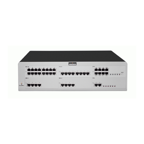
- Page 32 GENERAL DESCRIPTION PRODUCT PRESENTATION Rack 3 96 ports 1 CPU slot + 4 specific general-purpose slots (no UAI16 and MIX boards) Energy consumption 2,3 A / 150 W. Dimensions: H = 154 mm; W = 442 mm; D = 400 mm. Weight: 13 kg.
- Page 33 Based on more advanced telephony requirements (voice mail service on 6 or 8 ports), these packages allow upgrading to provide the most comprehensive Internet services (electronic mail server, Proxy and cache server, VPN and Voice over IP). Alcatel OmniPCX Office thus becomes an e-communication ser- ver.
- Page 34 Add-on module controller with an HSL1 board) MIX244 0, 2 or 4 T0 basic accesses ISDN network, analog Z MIX484 + 4 or 8 UA interfaces terminals and Alcatel MIX448 + 4 or 8 Z interfaces Reflexes stations MIX044 MIX084 MIX048 PRA-T2...
- Page 35 Optional boards Connections SLI4 4, 8 or 16 Z interfaces Analog Z terminals SLI8 SLI16 UAI4 4, 8 or 16 UA interfaces Alcatel Reflexes stations UAI8 Multi-Reflexes UAI16 4070 IO/EO DECT base stations FUNCTIONS PROVIDED AND HARDWARE REQUIRED e-SOLUTION VOICE only...
- Page 36 GENERAL DESCRIPTION PRODUCT PRESENTATION Réf. 3EH 21000 BSAA Ed. 04...
- Page 37 PRODUCT PRESENTATION CAPACITIES AND LIMITS File CAPACITIES AND LIMITS The following table gives the capacities provided by the various Alcatel OmniPCX Office solutions. S / e-S M / e-M L / e-L XL / e-XL Maximum limits System Type of module...
- Page 38 CAPACITIES AND LIMITS PRODUCT PRESENTATION S / e-S M / e-M L / e-L XL / e-XL Maximum limits Primary T2 access Basic T0 access IP trunks Total trunk lines and B-chan- nels Terminals + Work stations User directory numbers (***) Reflexes terminals + simple terminals (Z) Reflexes terminals...
- Page 39 File PRODUCT PRESENTATION CAPACITIES AND LIMITS S / e-S M / e-M L / e-L XL / e-XL Maximum limits Preannouncement from 4 to 8 Languages from 2 to 4 Directory entries 3000 Speed dial numbers 2200 Basic on hold music 16 seconds Customizable on hold music up to 2 minutes...
- Page 40 CAPACITIES AND LIMITS PRODUCT PRESENTATION cascading of the LAN switches (Uplink = always reserved on each LAN board) (**): Available from version R1.1 onwards (***): Subscribers numbersinclude all terminals and virtual users 13 auxiliary ports (VMU, Internet ac- cess, Remote access), main operator terminal number. (****): Hard disk obligatory (*****): Be aware that radio base station number dimensionning is adapted to mobile sets number.
- Page 41 File PRODUCT PRESENTATION CAPACITIES AND LIMITS BOARDS IMPLEMENTATION Rack 1 SLOT1 SLOT2 SLOT C PU BOARD SLOT 1 SLOT 2 CPU SLOT CPU, CPUe, MEX Obligatory MIX x/y/z Yes + UAI4, UAI8, UAI16 Yes + SLI4, SLI8 Yes + SLI16 PRA-T2, PRA-T1, DASS2, Yes + DLT2...
- Page 42 CAPACITIES AND LIMITS PRODUCT PRESENTATION BOARD SLOT 1-3 SLOT 2-4 SLOT 5 CPU SLOT CPU, CPUe, MEX Obligatory MIX x/y/z Yes + UAI4, UAI8, UAI16 Yes + SLI4, SLI8, SLI16 Yes + PRA-T2, PRA-T1, DASS2, Yes + DLT2 ATA2, ATA4 Yes + BRA2, BRA4, BRA8 Yes +...
- Page 43 File PRODUCT PRESENTATION CAPACITIES AND LIMITS PRA-T2, PRA-T1, DASS2, Yes + DLT2 ATA2, ATA4 Yes + BRA2, BRA4, BRA8 Yes + CoCPU, CoCPU@ Yes + LANX8, LANX16 Yes + Empty slot blanking cover Yes +: recommended slot Ed. 04 Réf. 3EH 21000 BSAA 7/10...
- Page 44 CAPACITIES AND LIMITS PRODUCT PRESENTATION POWER SUPPLY LIMITS The following tables give the details power consumption of the different items (boards and terminals) and the limit not to be exceeded for each model (all values are in W unit). The maximum budget at the charger level is also indicaded for each model and you have just to add the values for all items presents in the system.
- Page 45 File PRODUCT PRESENTATION CAPACITIES AND LIMITS Boards and terminals Rack 1 Rack 2 Rack 3 Datacom boards LANX 8 3,64 4,51 LANX 16 6,88 8,53 Mixed boards 4T0/8UA/4Z 2,90 4T0/4UA/8Z 3,45 4T0/4UA/4Z 2,13 8UA/4Z 2,39 4UA/8Z 2,96 4UA/4Z 1,86 Extension boards UAI 16 2,21 UAI 8...
- Page 46 CAPACITIES AND LIMITS PRODUCT PRESENTATION 10/10 Réf. 3EH 21000 BSAA Ed. 04...
- Page 47 Z interface for Alcatel Reflexes station (AP board) Analog trunk line interface (ATA board) SELV Alcatel Reflexes station interface (UAI board or Multi-Reflexes option 4099) 4070 IO/EO base station interface (UAI board) T0 interface (BRA board) T2/T1 interface (PRA board)
- Page 48 COMPLIANCE WITH STANDARDS PRODUCT PRESENTATION ESSENTIAL REQUIREMENTS This product complies with the core requirements of European Community R&TTE Directive 1999/5/ Electromagnetic compatibility : EN 5502 Ed. 1998 class B: Limits and methods of measuring the characteristics of radioelectric disturbances produced by information technology equipment. EN 55024 Ed.
- Page 49 BETWEEN ALCATEL OMNIPCX OFFICE File ENVIRONMENT COMPATIBILITY BETWEEN ALCATEL OMNIPCX OFFICE On the new generation Alcatel OmniPCX Office, it is possible to re use some equipments and terminals from the Alcatel Office range. TERMINAL COMPATIBILITY ON THE ALCATEL OMNIPCX OFFICE Compatible Alcatel Reflexes The complete range 2G : 4001, 4003, 4011, 4012, 4023, 4034, 4081L, 4081M and 4088.
- Page 50 INCOMPATIBLE HARDWARE PARTS ON ALCATEL OMNIPCX OFFICE The complete range of Alcatel Reflexes 1G (first generation). Alcatel mobile DECT sets 4075, 4074 B, 4074 Bex, 4074 H. Base station DECT RBS Alcatel 4070 IA and 4070 EA. The complete range Alcatel 160 sets.
- Page 51 Alcatel OmniPCX Office Hardware SECTION HARDWARE REF3EH 21000 BSAA Ed. 04...
- Page 53 ALCATEL OMNIPCX OFFICE HARDWARE Section Hardware RACK 1 - RACK 2 - RACK 3 MODULES FILE 1 CPU - CPUE BOARDS FILE 2 MEX BOARD FILE 3 COCPU - COCPU@ BOARDS FILE 4 BRA BOARD FILE 5 PRA BOARD FILE 6...
- Page 54 ALCATEL OMNIPCX OFFICE SECTION HARDWARE (INDEX) HARDWARE Section Hardware (Index) ATA BOARD FILE 7 BRA BOARD FILE 5 COCPU - COCPU@ BOARDS FILE 4 CPU - CPUE BOARDS FILE 2 LANX BOARD FILE 11 MAIN POWER SUPPLIES FILE 12 MEX BOARD...
- Page 55 HARDWARE RACK 1 - RACK 2 - RACK 3 MODULES File RACK 1 - RACK 2 - RACK 3 MODULES RACK 1 The RACK 1 module consists essentially of a plastic frame. The plastic frame receives all the parts for attaching the power supply board, the fans, the battery and the mains power connector, and everything needed to facilitate the routing of the cables.
- Page 56 RACK 1 - RACK 2 - RACK 3 MODULES HARDWARE RACK 2 AND RACK 3 The frame consists of a "U"-shaped sheath closed on the top by a riveted plate. The boards are guided by 2 (Rack 2) or 3 (Rack 3) rails riveted vertically to the frame. The enclosure consists of a metal top part, two metal side parts and a plastic front face.
- Page 57 HARDWARE CPU - CPUE BOARDS File CPU - CPUe BOARDS The CPU and CPUe boards (Processing Unit) present the following characteristics: CPU: call handling, 100-MHz processor, 32 MB SDRAM. CPUe: call handling, management of the router function for accessing the Internet, 133 MHz pro- cessor, 64 Mb S-DRAM, more powerful DSPs.
- Page 58 CPU - CPUE BOARDS HARDWARE DAUGHTER BOARDS The CPU - CPUe boards can take the following daughter boards: HSL (High Speed Link): for cabinet interconnections XMEM (eXtended MEMory): memory extension + 2.5-inch hard drive connection VoIP (Voice over IP): converts voice signals into data packets and back again AFU (Auxiliary Function Unit): support for auxiliary functions: general bell, doorphone, audio In, audio Out, etc.
- Page 59 File HARDWARE CPU - CPUE BOARDS OUTPUT PORTS (BOARD STIFFENER) PROCESSING UNIT AUDIO-OUT CONFIG POWER MODULE MODULE1 MODULE2 AUDIO-IN DOORPHONE PROCESSING UNIT CPUe AUDIO-OUT CONFIG POWER MODULE MODULE1 MODULE2 AUDIO-IN DOORPHONE Available functions: LAN: 10/100 base T Ethernet port (MDI-II/straight) AUDIO-OUT: loudspeaker, alarm and general bell interfaces;...
- Page 60 CPU - CPUE BOARDS HARDWARE MEANING OF THE LED INDICATIONS Name Color Function Green CPU functioning LED (flashing) POWER Red/Green Mains operation: steady green LED Battery operation: steady yellow LED Idle: flashing red LED Red/Green Both fans functioning: steady green LED 1 or both fans down: steady red LED Green LAN functioning LED (flashes when there is traffic)
- Page 61 File HARDWARE CPU - CPUE BOARDS GENERAL CONNECTION DIAGRAM Configuration without SLANX4 (recommended configuration) CoCPU board + SLanX4 board COPROCESSIN G UN IT CoCPU CPU board CoCPU COPROCESSIN G UNIT External LAN Switch LANX board LANX8 ETHERN ET LAN SWITCH General bell Loudspeaker Alarm...
- Page 62 CPU - CPUE BOARDS HARDWARE Configuration with SLANX4 CoCPU board + SLanX4 board CoCPU COPROCESSING UNIT CPU board CoCPU COPROCESSING UNIT External LAN Switch LANX board LANX8 ETHERNET LANSWITCH General bell Loudspeaker Alarm 12V serviceable voltage CPU board PROCESSING UNIT PC (PM5, NMC) Doorphone MEX board (extension unit 1)
- Page 63 File HARDWARE CPU - CPUE BOARDS CONNECTING A HARD DISK Hard disks are fitted using an XMEM board. Hard disk Support XMEM board CPU board 44-point connectors connected by a flat cable Important : During installation, always take anti-static precautions (wristband, heelpiece, etc.) befo- re handling the hard disk.
- Page 64 CPU - CPUE BOARDS HARDWARE Contact characteristics (same characteristics for the alarm and doorphone control contacts): Max. power: 10 W Max. voltage: 100 V Max. current: 500 mA CONNECTING A BACKGROUND MUSIC TUNER This is connected via the AUDIN input of the AUDIO-IN connector. PROCESSING UNIT Distribution panel Audio In A...
- Page 65 File HARDWARE CPU - CPUE BOARDS Distribution panel PROCESSING UNIT Alarm A Alarm device Alarm B Power supply Ed. 04 Réf. 3EH 21000 BSAA 9/12...
- Page 66 CPU - CPUE BOARDS HARDWARE CONNECTING A DOORPHONE The doorphone interface comprises an intercom and an optional doorstrike powered by the mains supply through a SELV (Safety Extra Low Voltage) transformer. It is connected via the DOORPHA and DOORPHB outputs (control contacts open when idle) of the DOORPHONE connector.
- Page 67 File HARDWARE CPU - CPUE BOARDS CONNECTING A GENERAL BELL The general bell is connected via the CENRG output of the AUDIO-OUT connector. PROCESSING UNIT Distribution panel CenRg A General call ringer CenRg B Power supply CONNECTING A BROADCAST LOUDSPEAKER Broadcast loudspeakers are connected via the AUDOUT output of the AUDIO-OUT connector.
- Page 68 CPU - CPUE BOARDS HARDWARE 12/12 Réf. 3EH 21000 BSAA Ed. 04...
- Page 69 HARDWARE MEX BOARD File MEX BOARD The MEX board (Module EXpansion) performs the controller functions in the add-on modules. Plug-in to BACKX board HSL1 Ed. 04 Réf. 3EH 21000 BSAA...
- Page 70 MEX BOARD HARDWARE DAUGHTER BOARD The MEX board is equipped with an HSL1 (High Speed Link) board for interconnecting with the basic module. OUTPUT PORTS (BOARD STIFFENER) MODULE EXPANSION POWER MAIN Available functions: MAIN: HSL to basic module. RJ45 pin MAIN outputs MEANING OF THE LED INDICATIONS Name...
- Page 71 HARDWARE COCPU - COCPU@ BOARDS File CoCPU - CoCPU@ BOARDS The CoCPU and CoCPU@ (CoProcessing Unit) boards offer applications such as Voice over IP and access to the Internet and to Internet services. Plug-in to BACKX board XMEM VOIP SDRAM ASPEN CoCPU CoCPU@...
- Page 72 COCPU - COCPU@ BOARDS HARDWARE DAUGHTER BOARDS The CoCPU - CoCPU@ boards can take the following daughter boards: VoIP (Voice Over IP): Gateway H323 with integrated Gatekeeper function; supports the manage- ment of CODECs and DSPs for IP telephony and IP Trunk (IP trunk lines) applications SLANX (Switched LANX): 4 LAN switch ports WAN: Ethernet link allowing the connection of an external DSL modem or an external router DAUGHTER BOARDS...
- Page 73 File HARDWARE COCPU - COCPU@ BOARDS OUTPUT PORTS (BOARD STIFFENER) COPROCESSING UNIT CoCPU Unit1 Unit 2 Unit 3 Uplink UNIT1 UNIT2 UNIT3 UP-LINK COPROCESSING UNIT CoCPU@ Unit1 Unit 2 Unit 3 Uplink UNIT1 UNIT2 UNIT3 UP-LINK Available functions: LAN: 10/100 base T Ethernet port (MDI-II/straight) WAN: Ethernet 10/100 Base T port (MDI-II/straight);...
- Page 74 COCPU - COCPU@ BOARDS HARDWARE CONNECTION The CoCPU boards are connected either to the CPU board (LAN port) or to a LAN switch port. See General Diagram in the CPU - CPUe board section. CONNECTING A HARD DISK Hard disks are fitted using an XMEM board. Hard disk Support XMEM board...
- Page 75 HARDWARE BRA BOARD File BRA BOARD The BRA board The BRA (Basic Rate Access) board provides the basic access points (2 x 64-Kbps B- channels + 1 x 16-Kbps D-channel per access) for connecting the system to the ISDN digital public network (point-to-point or multipoint T0 link).
- Page 76 Female RJ45, front RJ45 pin Outputs CONNECTING A T0 ACCESS The Alcatel OmniPCX system can be installed near the digital network termination or at a certain dis- tance (up to 350 m), as required. BRA8 ISDN ACCESS - T0 Distribution panel...
- Page 77 File PRA BOARD The PRA (Primary Rate Access) board provides 1 primary access for connecting the Alcatel OmniPCX system to the ISDN digital public network or to private networks: PRA -T2, DASS2, DLT2: 30 B-channels + 1 D-channel; 2048 kbps)
- Page 78 PRA BOARD HARDWARE OUTPUT PORTS (BOARD STIFFENER) T2 board example ISDN ACCESS - E1 PRA-T2 BUSY NETW II PBX X Female RJ45, front RJ45 pin NETW outputs PBX outputs NETW: connection to public network DLT. PBX: network operation (QSIG). BOARD TYPE DEFINITION (CITROEN STRAPS) The board type is defined by the Citroën strap solder: T2 (ex-factory) : no solders...
- Page 79 File HARDWARE PRA BOARD ALARM LEDS BUSY T2 Name T1 Name Function BUSY BUSY B-channels busy (red LED lights up if at least 1 B-channel is busy) RAI (ATD) Remote frame alarm (red LED lights up on alarm) AIS (SIA2M) Too many "1"s in the 2-Mbit binary train (red LED lights up on alarm) NOS (MS)
- Page 80 PRA BOARD HARDWARE Réf. 3EH 21000 BSAA Ed. 04...
- Page 81 HARDWARE ATA BOARD File ATA BOARD The ATA (Analog Trunk Access) board serves to connect analog trunk lines (TL). 2 board versions are available: ATA-2: 2 trunk lines ATA-4: 4 trunk lines Plug-in to BACKX board DSLAC DSLAC X1, X2, X3, X4: plug-in connectors for MET daughter boards (call charge metering receivers). Ed.
- Page 82 ATA BOARD HARDWARE OUTPUT PORTS (BOARD STIFFENER) ANALOG TRUNK ACCESS ATA4 PHONE Female RJ45, front RJ45 pin Outputs 1 to 4 SLI outputs PHONE outputs ZSETA ZSETB CONNECTING A TL Without TL forwarding ATA4 ANALOG TRUNK ACCESS Distribution panel Analog Public Network Réf.
- Page 83 File HARDWARE ATA BOARD With TL forwarding In the event of a power cut or CPU failure, this solution forwards the analog line connected to device 1 on the ATA board to another analog set in the system. ANALOG INTERFACES SLI16 ZA, ZB ATA4...
- Page 84 ATA BOARD HARDWARE ADAPTATION TO UK PROTOCOLS In accordance with the UK analogue public network, 2 types of ATA boards are available: ATA board (2 or 4 equipments) equipped with polarity inversion detectors. ATA LCG board (2 or 4 equipments) equipped with calibrated power failure detectors. Protocol Board type Supported functionality...
- Page 85 File MIX BOARD The MIX board The MIX (Mixed Lines) board serves to connect ISDN basic accesses (T0), Alcatel Re- flexes stations (UA) and 2-wire analog terminals (Z). 6 board versions are available: MIX244: 2 T0 accesses, 4 UA interfaces and 4 Z interfaces...
- Page 86 T0 outputs CONNECTING AN ANALOG STATION (Z) Follow the rules in the "SLI board" section. CONNECTING AN ALCATEL REFLEXES STATION Follow the rules in the "UAI board" section. CONNECTING A T0 BASIC ACCESS Follow the rules in the "BRA board" section.
- Page 87 HARDWARE UAI BOARD File UAI BOARD The UAI board allows the connection of Alcatel Reflexes stations (UA). 3 board versions are available: UAI4: 4 UA interfaces UAI8: 8 UA interfaces UAI16: 16 UA interfaces Plug-in to BACKX board UA interfaces 13 to 16...
- Page 88 UAI BOARD HARDWARE OUTPUT PORTS (BOARD STIFFENER) UAI16 DIGITAL INTERFACES Female RJ45, front RJ45 pin Outputs CONNECTING A REFLEXES STATION The terminals are equipped with a cable and a self-acting switch that plugs into the wall socket. Each terminal is connected up by a pair of 0.5 or 0.6 mm diameter wires. System - Reflexes station distances: 0.5 mm SYT type cable: 800 m (station without option) or 600 m (station with S0 or Z option) 278 type 0.6 mm cable: 1200 m (station without option) or 850 m (station with S0 or Z option)
- Page 89 HARDWARE SLI BOARD File SLI BOARD The SLI board (Single Line) allows the connection of 2-wire analog terminals (Z). 3 board versions are available: SLI4: 4 Z interfaces SLI8: 8 Z interfaces SLI16: 16 Z interfaces Plug-in to BACKX board Ed.
- Page 90 SLI BOARD HARDWARE OUTPUT PORTS (BOARD STIFFENER) ANALOG INTERFACES SLI16 Female RJ45, front RJ45 pin Outputs CONNECTING AN ANALOG Z STATION The sets are equipped with a cable and self-acting switch for connection to a wall socket. Each set is connected up with a pair of 0.5 or 0.6-mm wires (the maximum distance with 0.5-mm cabling is 1.3 km).
- Page 91 HARDWARE LANX BOARD File LANX BOARD The LanX board (Ethernet LAN Switch) serves to connect Ethernet terminals (IEEE 802.3 compatible). 2 board versions are available: LanX8: eight 10/100 BT Ethernet ports (ports 1 to 7: MDI-X/crossover; Uplink: MDI-II/straight) LanX16: sixteen 10/100 BT Ethernet ports (ports 1 to 15: MDI-X/crossover; Uplink: MDI-II/straight) Plug-in to BACKX board Converter KS8998...
- Page 92 LANX BOARD HARDWARE OUTPUT PORTS (BOARD STIFFENER) LANX16 ETHERNET LANSWITCH UP-LINK LANX8 ETHERNET LANSWITCH UP-LINK Each category-5 RJ45 connector has 2 green LEDs: LED A = link status and activity: • off: link disconnected • on: link connected blinking: link active LED B = full duplex/collision: •...
- Page 93 File HARDWARE LANX BOARD CONFIGURATION EXAMPLE Alcatel Server 1 Ethernet 10/100 Mbits SWITCH Ethernet 10/100 Mbits Up- Link Server 2 LANX8 ETHERNET LANSWITCH PROCESSING UNIT Port 4 Port 3 Ethernet 10/100 Mbits Port 2 Ethernet 10/100 Mbits Host 1 Port 1...
- Page 94 LANX BOARD HARDWARE Réf. 3EH 21000 BSAA Ed. 04...
- Page 95 HARDWARE MAIN POWER SUPPLIES File MAIN POWER SUPPLIES POWER SUPPLY PS1 Power supply PS1 provides the different voltages required to operate a Rack 1 module and also acts as a backplane board (slots 1, 2 and CPU). Power supply connectors for fans SLOT 1 12V CPU fuse...
- Page 96 MAIN POWER SUPPLIES HARDWARE POWER SUPPLY PS2 Power supply PS2, which provides the different voltages required to operate a Rack 2 module, compri- ses 2 boards: PCH2 :charger board PCO2 :converter board Fan power supply connectors Mains power connexion 12V fuse for CPU (1A fast-acting) 110V/230V selection: -jumpers in 1-2: 110 V...
- Page 97 File HARDWARE MAIN POWER SUPPLIES POWER SUPPLY PS3 Power supply PS3, which provides the different voltages required to operate a Rack 3 module, compri- ses 2 boards: PCH3 :charger board PCO3 :Converter board Fan power supply connectors Mains power connexion 12V fuse for CPU (1A fast-acting) 110V/230V selection:...
- Page 98 MAIN POWER SUPPLIES HARDWARE BATTERIES Equipment: Rack 1: 1 battery Rack 2: 2 batteries mounted in parallel Rack 3: 3 batteries mounted in series Battery characteristics: sealed lead battery 1.2 Ah / 12 V fire resistance better than or equal to UL94-V2 Maintenance To guarantee system shutdown without data loss in the event of a mains power failure or the mains plug is unplugged at the wall socket, replace the batteries every two years.
- Page 99 UPS (Uninterruptible Power Source) A Pulsar ellipse UPS (Uninterruptible Power Source) increases the backup time generally provided by the system batteries.A maximum of 2 Alcatel OmniPCX modules can be connected to a UPS. Cable provided with UPS Mains power cable provided with...
- Page 100 MAIN POWER SUPPLIES HARDWARE Equipment: The following table indicates the UPS models to use with each Alcatel OmniPCX Office system for a power autonomy of about 1 hour (40 minutes for the XL model used with a standard configuration). System...
- Page 101 Alcatel OmniPCX Office Terminals SECTION TERMINALS REF3EH 21000 BSAA Ed. 04...
- Page 103 ALCATEL OMNIPCX OFFICE TERMINALS Section Terminals ALCATEL REFLEXES 3G TERMINALS FILE 1 MULTI-REFLEXES 4099 HUB FILE 2 DECT 4070 IO/EO BASE STATIONS FILE 3 MOBILE REFLEXES 100/200 HANDSETS FILE 4 FAST IP REFLEXES TERMINALS FILE 5 PIMPHONY REFLEXES WORKSTATIONS FILE 6...
- Page 104 ALCATEL OMNIPCX OFFICE SECTION TERMINALS (INDEX) TERMINALS Section Terminals (Index) ALCATEL REFLEXES 3G TERMINALS FILE 1 DECT 4070 IO/EO BASE STATIONS FILE 3 MOBILE REFLEXES 100/200 HANDSETS FILE 4 PIMPHONY REFLEXES WORKSTATIONS FILE 6 EARLIER GENERATION SETS FILE 8 FAST IP REFLEXES TERMINALS...
- Page 105 TERMINALS ALCATEL REFLEXES 3G TERMINALS File ALCATEL REFLEXES 3G TERMINALS TERMINAL FEATURES FEATURE DEDICATED DIGITAL SETS FIRST EASY PREMIUM ADVANCED Handset Loudspeaker Buzzer 1 x 20 character display 2 x 40 character display Pictograms associated with programma- ble keys Soft keys...
- Page 106 ALCATEL REFLEXES 3G TERMINALS TERMINALS Station 4004/FIRST Station 4010/EASY Station 4020/PREMIUM Station 4035/ADVANCED Réf. 3EH 21000 BSAA Ed. 04...
- Page 107 ALCATEL REFLEXES 3G TERMINALS 4097 CBL ADAPTER Alcatel Advanced sets can be equipped with a 4097 CBL UA/DECT adapter and can therefore com- municate with the system over a DECT radio link. This device means you no longer have to worry about cabling constraints.
- Page 108 Optional Alcatel UA3G station Module Notas : The optional modules can also be used with Reflexes2G sets (the previous generation). Alcatel Premium and Advanced sets have a slot under the panel for the optional module. Optional port Optional Alcatel module...
- Page 109 File TERMINALS ALCATEL REFLEXES 3G TERMINALS 4093 ASY-CTI module This module allows the device to be connected to the system via a UA link, a PC-type peripheral device by means of an RS232 link (CTI port) and an DTE data terminal (V24 port).
- Page 110 ALCATEL REFLEXES 3G TERMINALS TERMINALS 4094 ISW module This module connects an S0 terminal to the system via a UA link. This optional module provides an S0 power bus which requires an external power supply (230V AC/ 42V DC adapter), allowing terminals without their own power supply (ISDN terminals, etc.) to be con- nected to the bus.
- Page 111 File TERMINALS ALCATEL REFLEXES 3G TERMINALS 4095 AP module This interface connects an analog peripheral such as a modem, teletext or answering machine to the system via a UA link. The optional module supplies the terminal (DTMF signaling, ringer) and therefore requires an external power supply (230V AC/30V DC mains adapter).
- Page 112 ALCATEL REFLEXES 3G TERMINALS TERMINALS Réf. 3EH 21000 BSAA Ed. 04...
- Page 113 TERMINALS MULTI-REFLEXES 4099 HUB File MULTI-REFLEXES 4099 HUB Multi-Reflexes option 4099 connects up 3 Alcatel Reflexes terminals using just one UA system link; this option makes it easier to install additional Reflexes terminals. UA/Reflexes 2 UA/Reflexes 3 UA/PBX UA/Reflexes 1 Option 4099 separates out the 3 B-channels of the UA interface into 3 terminal interfaces.
- Page 114 Alcatel Reflexes 2G sets with or without add-on modules (a maximum of 3 modules per option 4099). Alcatel Reflexes 3G sets with or without add-on modules or the 4091 CTI option (the 2 sub-groups are mutually exclusive). a 4088 adapter with a V24 4083 ASM board.
- Page 115 TERMINALS DECT 4070 IO/EO BASE STATIONS File DECT 4070 IO/EO BASE STATIONS The DECT 4070 IO/EO (internal/external) base station can be connected to: 1 UA interface: 3 DECT channels 2 UA interfaces: 6 DECT channels Antennae Local power supply Screw terminal block Impenetrable plastic Case...
- Page 116 DECT 4070 IO/EO BASE STATIONS TERMINALS Local power supply It is possible to connect a local power supply (230V/42V – 150 mA adapter) to an accessible socket on the lower part of the 4070 IO/EO base. The local power supply is used in the following cases: main power supply not authorized on the line's wires (depending on specific installation require- ments) to increase the cable length between the interface and the station...
- Page 117 TERMINALS MOBILE REFLEXES 100/200 HANDSETS File MOBILE REFLEXES 100/200 HANDSETS FEATURE Mobile Reflexes 100 Mobile Reflexes 200/ 200 Ex Graphic matrix display: 96 x 48 pixels Backlighting Vibrator YES (except Mobile Reflexes 200 Ex) Navigator Headset socket Loudspeaker Belt clip Color Dark green Aluminum...
- Page 118 MOBILE REFLEXES 100/200 TERMINALS HANDSETS Réf. 3EH 21000 BSAA Ed. 04...
- Page 119 File TERMINALS MOBILE REFLEXES 100/200 HANDSETS CHARGERS Mobile Reflexes handsets are listed separately from the various battery charging devices available. The charger must therefore be ordered separately and selected from the models on offer, all of which are compatible with the Ni-MH or Li-Ion batteries used in Mobile Reflexes handsets. The Mobile Reflexes 200 Ex handset does not support battery charging and therefore has to be used in conjunction with a "Dual-desktop "...
- Page 120 MOBILE REFLEXES 100/200 TERMINALS HANDSETS Réf. 3EH 21000 BSAA Ed. 04...
- Page 121 TERMINALS FAST IP REFLEXES TERMINALS File FAST IP REFLEXES TERMINALS Fast IP Reflexes terminals are Reflexes sets with a 4098 FRE ("IP Enabler") module. There are two mo- dels: Fast IP Advanced Reflexes / 4037F Fast IP Premium Reflexes / 4022F Mains power IP ENABLER 4098 FRE...
- Page 122 FAST IP REFLEXES TERMINALS TERMINALS 4098 FRE MODULE (IP Enabler) UA output (to station) LAN CPU PC connection Leds Switch External power supply LAN connection The switch can be used to reset the module with the previous software version (only possible in boot phase).
- Page 123 File PIMPHONY REFLEXES WORKSTATIONS The standard Alcatel OmniPCX Office offering includes an integrated CTI server (TAPI 2.0) that opens up a broad range of third party CTI applications. PIMphony Reflexes is a PC-based workstation equipped with the following PIMphony applications:...
- Page 124 PIMPHONY REFLEXES TERMINALS WORKSTATIONS Réf. 3EH 21000 BSAA Ed. 04...
- Page 125 TERMINALS VBTEL VISUALLY IMPAIRED OPERATOR STATION File VBTEL VISUALLY IMPAIRED OPERATOR STATION The VBTEL terminal is designed to act as a display for visually impaired operators, conveying the in- formation presented on Reflexes terminals. There are 2 models: VBTEL 20: equipped with a piezoelectric Braille touchpad with 20 characters and 32 command keys.
- Page 126 VBTEL VISUALLY IMPAIRED OPERATOR TERMINALS STATION Perkins alphabetical order, the 2 others being the backspace (7) and space keys (8). A set of 20 or 40 piezoelectric cells located above the Braille keyboard enables Braille characters to be displayed. Each cell contains 8 points: points 1 to 6 serve to form the 64 characters of the Braille alphabet;...
- Page 127 DECT 4075, 4074B, 4074H and 4074 BEx mobile sets Alcatel 160 sets Alcatel 4120 sets (900A and 900B) REFLEXES 2G 40XX* SETS Reflexes terminals from the 2G range are supported by Alcatel OmniPCX Office for migration purpo- ses. *Depending on country/distribution network FEATURE...
- Page 128 EARLIER GENERATION SETS TERMINALS Station 4012 Station 4011 Station 4003 Station 4023 Station 4034 2/14 Réf. 3EH 21000 BSAA Ed. 04...
- Page 129 File TERMINALS EARLIER GENERATION SETS MOUNTING THE ADD-ON MODULES A kit (a 10-cm cable with two 8-pin modular jacks) connects the 4081M or 4081L add-on modules to 4012, 4023 and 4034 sets (there is no limit on the number of add-on modules in the system). Procedure Turn the set and the module upside down Connect the cable to the set and the module...
- Page 130 TERMINALS CONNECTING THE 4088 ADAPTER The 4088 adapter is connected directly to an Alcatel UA set interface and enables the installation of an optional 4083 ASM, 4083 PCT, 4084 IS/ISW or 4085 AB board. Output pins of the 6-pin Modular jack for connection to UAI :...
- Page 131 File TERMINALS EARLIER GENERATION SETS REFLEXES 2G 50XX * SETS Reflexes terminals from the 2G range are supported by Alcatel OmniPCX Office for migration purpo- ses. *Depending on country/distribution network FEATURE Characteristics 5010 5015 5018 5022 5028 Handset Loudspeaker Display...
- Page 132 EARLIER GENERATION SETS TERMINALS STATION 5018 STATION 5010 STATION 5015 STATION 5028 STATION 5022 6/14 Réf. 3EH 21000 BSAA Ed. 04...
- Page 133 TERMINALS EARLIER GENERATION SETS OPTIONS FOR UA 2G SETS 4012, 4034, 5022 and 5028 sets on the Alcatel OmniPCX system can take an optional interface that plugs into the rear of the set: 4083 (or 5083) ASM: V24 - MAC/PC option...
- Page 134 EARLIER GENERATION SETS TERMINALS X401: 8 pin female connector for PCs Female outlet Signal Function Circuit (view from the bottom of the station PCRTS Request to send 7 (not used) Clear to send PCCTS 8 (not used) 6 (not used) PCTD Data transmission PCSG...
- Page 135 File TERMINALS EARLIER GENERATION SETS X301: connector for the S0 bus 1 and 2 - not used 5 - TX - 3 - RX + 6 - RX - 4 - TX + 7 and 8 - not used Short passive bus Long point-to-point bus (X102 across 1-2) (X102 across 2-3) X302...
- Page 136 EARLIER GENERATION SETS TERMINALS Connecting analog terminals The Z station interface is of type TNV (Telecommunication Network Voltage) with mains supply. The connection distance of an analog terminal to this interface is limited to 20 meters. The user of a set connected to this interface has the same operation possibilities as a user using a classic Z interface (restriction: the set's Message LED cannot be used).
- Page 137 File TERMINALS EARLIER GENERATION SETS DECT 4074 HANDSETS FEATURE DECT HANDSETS 4074 GB 4074 GH 4074GI 4074GC Handset with adjustable volume ON/OFF switch (or keys) 16 character display Numeric keypad keys Line keys Programmable keys Navigator keys Headset socket Keypad backlighting Protective cover Integrated vibrator Charger...
- Page 138 EARLIER GENERATION SETS TERMINALS Fri 15 Mar 14:30 Fri 15 Mar 14:30 4074 GB/GC station 4074 GH/GI station 4071 DA charger 4071 BC charger 4071 BA charger 12/14 Réf. 3EH 21000 BSAA Ed. 04...
- Page 139 File TERMINALS EARLIER GENERATION SETS 4073 GS SMART DECT HANDSET FEATURE 4073 GS SMART Handset On/Off Key Display: 2 x 16 alphanumeric characters + 1 line of 8 icons Numeric keypad keys Navigator keys Function keys Vibrator Ed. 04 Réf. 3EH 21000 BSAA 13/14...
- Page 140 EARLIER GENERATION SETS TERMINALS 14/14 Réf. 3EH 21000 BSAA Ed. 04...
- Page 141 Alcatel OmniPCX Office CALL SERVER : Telephone features SECTION CALL SERVER : TELEPHONE FEATURES REF3EH 21000 BSAA Ed. 04...
- Page 143 ALCATEL OMNIPCX OFFICE CALL SERVER : TELEPHONE FEATURES Section CALL SERVER : Telephone features RESOURCE KEYS (ASSOCIATED OPERATING MODES) FILE 1 TRUNK GROUPS FILE 2 HUNTING GROUPS FILE 3 OPERATOR STATIONS (OPERATOR GROUPS) FILE 4 SPECIFIC OPERATOR STATION SERVICES FILE 5...
- Page 144 ALCATEL OMNIPCX OFFICE SECTION CALL SERVER : TELEPHONE CALL SERVER : TELEPHONE FEATURES FEATURES MAKING/ANSWERING A CALL FILE 22 PRIORITY CALLS FILE 23 CAMP-ON ON BUSY STATION OR GROUP FILE 24 ANSWERING CAMPED-ON CALLS FILE 25 THREE PARTY CALLS FILE 26...
- Page 145 Fiche ALCATEL OMNIPCX OFFICE CALL SERVER : TELEPHONE FEATURES SECTION CALL SERVER : TELEPHONE FEATURES CUSTOMIZING STATIONS FILE 46 TEAMWORK FILE 47 ACCOUNT CODE/SUBSTITUTION FILE 48 ALLOCATION OF A TRUNK LINE FILE 49 METER TOTAL RECALL FILE 50 REMOTE SUBSTITUTION...
- Page 146 ALCATEL OMNIPCX OFFICE SECTION CALL SERVER : TELEPHONE CALL SERVER : TELEPHONE FEATURES FEATURES (INDEX) Section CALL SERVER : Telephone features (Index) FAX NOTIFICATION FILE 53 ACCOUNT CODE/SUBSTITUTION FILE 48 ALLOCATION OF A TRUNK LINE FILE 49 ALTERNATIVE CLIP AND COLP NUMBERS...
- Page 147 Fiche ALCATEL OMNIPCX OFFICE CALL SERVER : TELEPHONE FEATURES SECTION CALL SERVER : TELEPHONE FEATURES (INDEX) EXTERNAL FORWARDING FILE 32 FAX CALL ROUTING FILE 52 FORWARDING FILE 28 FORWARDING TO VOICE MAIL UNIT FILE 30 HEADSET FEATURES FILE 43 HUNTING GROUPS...
- Page 148 ALCATEL OMNIPCX OFFICE SECTION CALL SERVER : TELEPHONE CALL SERVER : TELEPHONE FEATURES FEATURES (INDEX) SPECIFIC OPERATOR STATION SERVICES FILE 5 SPLITTING FILE 9 STATION COMFORT FEATURES FILE 41 TEAMWORK FILE 47 TEXT MAIL/DELAYED CALLBACK REQUEST FILE 40 THREE PARTY CALLS...
- Page 149 CALL SERVER : TELEPHONE FEATURES RESOURCE KEYS (ASSOCIATED OPERATING MODES) File RESOURCE KEYS (ASSOCIATED OPERATING MODES) DESCRIPTION A resource key is used to take a line in order to make or receive a call. When a station has at least two resource keys, it is said to be multiline. In this mode, the user presses the resource key associated with the correspondent he wants to contact (using the shuttle call function, for example).
- Page 150 RESOURCE KEYS (ASSOCIATED CALL SERVER : TELEPHONE FEATURES OPERATING MODES) by MMC-PM5 (Expert View): Subscribers/Basestations List -> Subscribers/Basestations List -> Profiles. by MMC-PM5 (Easy view): Subscriber profiles by MMC-Station: TerPro. Réf. 3EH 21000 BSAA Ed. 04...
- Page 151 File CALL SERVER : TELEPHONE FEATURES RESOURCE KEYS (ASSOCIATED OPERATING MODES) Authorize or cancel selection of an RSB if the external call arrives on a line which does not belong to the trunk programmed for this key: by MMC-PM5 (Expert View): System Miscellaneous ->...
- Page 152 RESOURCE KEYS (ASSOCIATED CALL SERVER : TELEPHONE FEATURES OPERATING MODES) More details about the abbreviations RGM, RGO, RSL, etc. can be found in the glossary. ADDITIONAL INFORMATION A resource key manages only one communication at a time. Z and First Reflexes stations are monoline; all other stations are multiline. The Reflexes 2G 4003 can be either monoline or multiline.
- Page 153 Operator Groups as well as the default Operator Group. The second Alcatel Reflexes station is a Secretary terminal and the third is a Manager terminal. Only Advanced or Premium Reflexes stations can provide the Manager/Secretary facility.
- Page 154 RESOURCE KEYS (ASSOCIATED CALL SERVER : TELEPHONE FEATURES OPERATING MODES) PABX mode Differences from Key system mode: the first 2 line keys are replaced by "Ext. Call" (access to the public network with 9); the other line keys are replaced by undefined call keys; these can be programmed with an internal destination (station) or external destination (number preceded by public network access prefix).
- Page 155 CALL SERVER : TELEPHONE FEATURES TRUNK GROUPS File TRUNK GROUPS DESCRIPTION Trunk groups are used to make calls to the network. A trunk group is made up of at least one analog line or B channel. Each bundle has: a directory number defined in the main numbering plan a management type: cyclic or sequential barring and traffic sharing link categories (see "Link Categories") CONFIGURATION...
- Page 156 TRUNK GROUPS CALL SERVER : TELEPHONE FEATURES To specify whether or not to authorize all the users to seize an analog line with predetermined rou- ting for outgoing calls: by MMC-PM5 (Expert View): System Miscellaneous -> Memory Read/Write -> Misc. Labels -> "TonPrRng" by MMC-Station: Global ->...
- Page 157 CALL SERVER : TELEPHONE FEATURES HUNTING GROUPS File HUNTING GROUPS DESCRIPTION Creating Hunting Groups makes it possible to call several stations using a single directory number; a single member of the group answers the call for the whole group. Each group has: a directory number defined in the main numbering plan a parallel, cyclic or sequential management type an operation type, either "setup"...
- Page 158 HUNTING GROUPS CALL SERVER : TELEPHONE FEATURES To authorize the immediate group forwarding or withdrawal (see "Forwarding") of group calls from the last member of a group (only with MMC-PM5 (Expert View)): System Miscellaneous -> Feature Design ->"Disconnect Last Group Member Allowed" Defining the dynamic routing parameters of a group: by MMC-PM5 (Expert View): Hunting Groups ->...
- Page 159 File CALL SERVER : TELEPHONE FEATURES HUNTING GROUPS ACTIVATION/USE Depending on the management type chosen for the group, the system makes the stations ring as fol- lows: Management type parallel cyclic sequential Stations rung all the free stations in the group 1st free station following the last 1st free station in the program- selected...
- Page 160 HUNTING GROUPS CALL SERVER : TELEPHONE FEATURES ADDITIONAL INFORMATION The maximum number of groups in a system is 50 (Hunting Groups + Broadcast Groups + pickup groups). The maximum number of stations in a group is 32. In SETUP mode and if the address "BusyGrpInd" = 1, the maximum number of calls camped onto a Hunting Group is equal to the number of members in the group.
- Page 161 CALL SERVER : TELEPHONE FEATURES OPERATOR STATIONS (OPERATOR GROUPS) File OPERATOR STATIONS (OPERATOR GROUPS) DESCRIPTION An operator station basically makes it possible to distribute calls arriving on the network. Such a station has the following characteristics: camp-on always authorized intrusion always authorized access to certain programming features Any station connected to the system can be an Operator Station, but, to have all the features of an operator, the station must:...
- Page 162 OPERATOR STATIONS (OPERATOR CALL SERVER : TELEPHONE FEATURES GROUPS) An Operator Group can have: stations the general bell (see "Connection of a general bell") 1 dissuasion message (see "Automatic Welcome /Pre-announcement") Default Operator Group This group (index 8): is available no matter what the time range can have up to 8 members including the general bell comes into service ...
- Page 163 File CALL SERVER : TELEPHONE FEATURES OPERATOR STATIONS (OPERATOR GROUPS) CONFIGURATION Configuring the Operator Groups: by MMC-PM5 (Expert View): Attendant Group List by MMC-Station: Groups -> OpGrp Modifying the internal call number of the Operator Groups: by MMC-PM5 (Expert View): Numbering -> Internal Numbering Plan by MMC-Station: NumPln ->...
- Page 164 OPERATOR STATIONS (OPERATOR CALL SERVER : TELEPHONE FEATURES GROUPS) To authorize external calls arriving on an analog interface (TLC, ATL, DDI, etc) to camp on the group (or prevent them from doing so) – MMC-PM5 (Expert View) only: External Lines -> Protocols -> Parameters -> "Ringing Mandatory": To authorize external calls arriving on a digital interface (T0, T2, etc), to camp on the group (or prevent them from doing so) –...
- Page 165 File CALL SERVER : TELEPHONE FEATURES OPERATOR STATIONS (OPERATOR GROUPS) ACTIVATION/USE Operator call The members Restricted mode of the default activated by an operator operator ? group ring Operator group active during time range The free operators ring and the Is the group call is camped on the busy available ?
- Page 166 OPERATOR STATIONS (OPERATOR CALL SERVER : TELEPHONE FEATURES GROUPS) ADDITIONAL INFORMATION The maximum number of Operator Groups in a system: 8, default operator included. The maximum number of stations in an Operator Group: 8. Forwarding of the last member of the Operator Group (except for the default Operator Group) can be authorized by programming.
- Page 167 CALL SERVER : TELEPHONE FEATURES SPECIFIC OPERATOR STATION SERVICES File SPECIFIC OPERATOR STATION SERVICES DESCRIPTION An Operator Station can: switch the entire installation to normal or restricted mode, independently of the time range (see "Normal/Restricted service (system level)") reserve a trunk group (the last) for exclusive use of the Operator Stations. Each O.S. in the active group can use this trunk group for communications with the network.
- Page 168 SPECIFIC OPERATOR STATION CALL SERVER : TELEPHONE FEATURES SERVICES CONFIGURATION For each time-range, define whether attendant diversion is activated when the OS switches ma- nually to restricted mode – MMC-PM5 (Expert View) only: Time Ranges -> "All Days" To define the type of mechanism used to forward external incoming calls to a network number: rerouting or joining (see "External Forwarding"...
- Page 169 File CALL SERVER : TELEPHONE FEATURES SPECIFIC OPERATOR STATION SERVICES ACTIVATION/USE P.K.: Programmed Key – defined using MMC-PM5 (expert View) or MMC-Station Switch to restricted mode When the system operates in normal mode, P.K.: NRMode + operator code Reservation of last trunk group P.K.: Reserv + operator code Broadcasting music on an ex- P.K.: BkgMus+ operator code...
- Page 170 SPECIFIC OPERATOR STATION CALL SERVER : TELEPHONE FEATURES SERVICES ADDITIONAL INFORMATION There is no particular signal to indicate attendant diversion when it is activated by scheduling. The icon or the LED associated with the NRmode programmed key is lit when one of the O.S. has used this key.
- Page 171 CALL SERVER : TELEPHONE FEATURES LINK CATEGORIES File LINK CATEGORIES DESCRIPTION Link categories enable the system to authorize or inhibit connection between an internal user and a network subscriber. There are 3 types of link category: speed dial rights: access to the collective speed dial numbers barring link category: access to dialing prefixes traffic sharing link category: access to bundles (see also file "Bundles") Link categories are attributed as follows:...
- Page 172 LINK CATEGORIES CALL SERVER : TELEPHONE FEATURES by MMC-PM5 (Expert View): • for the users: Subscribers/Basestations List -> Subscribers/Basestations List -> Details -> Collective Speed Dial for access: External Lines -> List of Accesses -> Details -> Speed Dial by MMC-Station: •...
- Page 173 File CALL SERVER : TELEPHONE FEATURES LINK CATEGORIES Modifying the default barring link categories: by MMC-PM5 (Expert View): • for the users: Subscribers/Basestations List -> Subscribers/Basestations List -> Details -> Barring • for the trunk groups: External Lines -> Trunk Groups -> Details -> Link-Cat for access: External Lines ->...
- Page 174 LINK CATEGORIES CALL SERVER : TELEPHONE FEATURES ACTIVATION/USE Is the external call made by means of a collective speed dial number? Analysis of the speed Analysis of the user and trunk dial rights of the station Group traffic sharing Lcs and of the class of the in the traffic sharing matrix speed dial number...
- Page 175 CALL SERVER : TELEPHONE FEATURES BARRING File BARRING DESCRIPTION Barring comes into effect after the system has authorized connection between the user and the entered trunk group (following analysis of the traffic sharing link categories: see "Link Categories"). Barring makes it possible to define whether an internal user (or an access, in the case of transit) is authorized to make a call to the network, or not (other than by using the collective speed dial numbers), depending on the prefix (i.e.
- Page 176 BARRING CALL SERVER : TELEPHONE FEATURES Creating barring tables (adding a "!" authorizes or inhibits a complete barring level) – MMC-PM5 (Expert View) only: Barring -> Barring Tables To authorize or deny access to the network by transfer, for each station – MMC-PM5 (Expert View) only: Subscribers/Basestations List ->...
- Page 177 File CALL SERVER : TELEPHONE FEATURES BARRING ADDITIONAL INFORMATION The 6 prefix tables altogether (or barring levels) can have over 100 prefixes. Each prefix has a maximum of 10 digits (0 to 9, * and #). A private subscriber cannot be connected to the network (nor receive calls from or make calls to the network).
- Page 178 BARRING CALL SERVER : TELEPHONE FEATURES Réf. 3EH 21000 BSAA Ed. 04...
- Page 179 CALL SERVER : TELEPHONE FEATURES END OF DIALING DETECTION File END OF DIALING DETECTION DESCRIPTION On analog trunk lines, end of dialing detection makes it possible to define the moment when the system can release the DTMF receivers and carry out the bi-directional switching of the line. The system uses the end of dialing prefix table to ascertain the length (number of digits) of the numbers transmitted.
- Page 180 END OF DIALING DETECTION CALL SERVER : TELEPHONE FEATURES ACTIVATION/USE Trunk line seizure The system uses the reference counter for Do the first digits correspond The system uses the all the lines and to a prefix configured in the counter value associated detects end of dialing end of dialing table of prefixes with this prefix...
- Page 181 CALL SERVER : TELEPHONE FEATURES SPLITTING File SPLITTING DESCRIPTION The splitting mechanism enables a user to dial a number on an analog trunk line or behind a PABX, without having to wait for any dialing splits. It is accessed: by manual dialing by automatic dialing (last number redial, temporary memory number, speed dial number) Splitting can be of two types: tone detection: TONE in the splitting prefix table...
- Page 182 SPLITTING CALL SERVER : TELEPHONE FEATURES CONFIGURATION Programming the line seizure type of splitting: by MMC-PM5 (Expert View): Numbering -> Splitting Table by MMC-Station: EODPfx -> EODial -> Split -> TonDet Programming or modifying the splitting prefix table: by MMC-PM5 (Expert View): Numbering -> Splitting Table by MMC-Station: EODPfx ->...
- Page 183 File CALL SERVER : TELEPHONE FEATURES SPLITTING ADDITIONAL INFORMATION Maximum number of prefixes in the table of splitting prefixes: 16. Maximum number of digits per prefix: 4. Ed. 04 Réf. 3EH 21000 BSAA...
- Page 184 SPLITTING CALL SERVER : TELEPHONE FEATURES Réf. 3EH 21000 BSAA Ed. 04...
- Page 185 CALL SERVER : TELEPHONE FEATURES CALL DISTRIBUTION (DYNAMIC ROUTING) File CALL DISTRIBUTION (DYNAMIC ROUTING) DESCRIPTION The system can automatically re-route: a call from the network and destined for the active Operator Group, or the default Operator Group (see "Operator stations") a call arriving from the network and currently in transit a DDI call (Direct Dialing Inward) from the network and destined for a station or a Hunting Group an external call on a "personalized"...
- Page 186 CALL DISTRIBUTION (DYNAMIC CALL SERVER : TELEPHONE FEATURES ROUTING) system in normal or restricted service (see "Normal / restricted service (system level)") dissuasion message programmed in the active Operator Group (see "Automatic welcome") welcome message transmitted or not (see Automatic Welcome (Pre-announcement)) destination station directory number: programmed in the public, private numbering plan (see "In- coming transit") or main only type of call: for a private subscriber or not...
- Page 187 File CALL SERVER : TELEPHONE FEATURES CALL DISTRIBUTION (DYNAMIC ROUTING) Defining the dynamic routing parameters for a resource key: by MMC-PM5 (Expert View): Subscribers/Basestations List -> Subscribers/Basestations List -> Details -> Keys -> Resource Key -> Dyn. Rout. by MMC-Station: Subscr -> Keys -> Modify -> Resou -> DynRou Defining the dynamic routing parameters for a station: by MMC-PM5 (Expert View): Subscribers/Basestations List ->...
- Page 188 CALL DISTRIBUTION (DYNAMIC CALL SERVER : TELEPHONE FEATURES ROUTING) ACTIVATION/USE Dynamic forwarding general principle Incoming internal or external call Initial destination (D0) rings Has D0 answered Conversation the call before time-out T1 has expired? Destination level 1 (D1) also rings Has D0 or D1 answered the call Conversation...
- Page 189 File CALL SERVER : TELEPHONE FEATURES CALL DISTRIBUTION (DYNAMIC ROUTING) Dynamic routing and call forwarding (see "Forwarding") Incoming call (int/ext) Station in Destined for a Hunting group immediate station or a in immediate forwarding hunting group forwarding? Hunting group Station Forwarding Forwarding destination...
- Page 190 CALL DISTRIBUTION (DYNAMIC CALL SERVER : TELEPHONE FEATURES ROUTING) ADDITIONAL INFORMATION The sub-address and User to User Signaling (UUS) are not re-routed after a forwarding, a transfer or a call pick-up. When dynamic routing is active but D1 or D2 is not programmed, or T1 or T2 is not used, the sys- tem moves onto the next stage.
- Page 191 CALL SERVER : TELEPHONE FEATURES NORMAL AND RESTRICTED SERVICE File NORMAL AND RESTRICTED SERVICE NORMAL AND RESTRICTED SERVICE - SYSTEM LEVEL Description The service mode affects the way in which the system distributes incoming calls and controls users' outgoing calls. A day can be divided into a maximum of 7 time ranges each varying in duration.
- Page 192 NORMAL AND RESTRICTED SERVICE CALL SERVER : TELEPHONE FEATURES Activation/Use Switching to RESTRICTED mode by an OPERATOR? Time range in Normal Restricted NORMAL or RESTRICTED mode? OPERATOR HUNTING GROUP ASSOCIATED TO THE TIME RANGE RESTRICTED MODE Are all the operators DEFAULT OPERATOR of the current group GROUP...
- Page 193 File CALL SERVER : TELEPHONE FEATURES NORMAL AND RESTRICTED SERVICE FORWARDING OF ALL EXTERNAL INCOMING CALLS The system is made up of two public numbering plans, one of which is used in normal service while the other is used in restricted service. The restricted public numbering plan can be configured in such a way that certain DDI numbers are redirected to external destinations (using the group directory or the ARS mechanism) while others (Fax for example) reach their intended internal destinations.
- Page 194 NORMAL AND RESTRICTED SERVICE CALL SERVER : TELEPHONE FEATURES Restricted service public numbering plan Begin Base Function Station Collective Speed Dial Collective Speed Dial Collective Speed Dial Station Hunting Group Collective Speed Dial Internal numbering plan Begin Base Function 8000 8010 Collective Speed Dial Collective Speed Dial...
- Page 195 File CALL SERVER : TELEPHONE FEATURES NORMAL AND RESTRICTED SERVICE NORMAL AND RESTRICTED SERVICE – USER LEVEL Description Depending on the time range, the system operates in either normal or restricted mode. The service mode affects the way in which the system distributes incoming calls and controls users' outgoing calls. The installer can also configure the operation in "user"...
- Page 196 NORMAL AND RESTRICTED SERVICE CALL SERVER : TELEPHONE FEATURES Activation/Use Does the user have "inhibit restricted mode" feature rights? Is the user in restricted mode during the applicable time range? NORMAL USER SERVICE RESTRICTED USER SERVICE and/or Set locked by user? Set locked by user? SERVICE LOCKED Additional Information...
- Page 197 CALL SERVER : TELEPHONE FEATURES AUTOMATIC WELCOME (PRE- ANNOUNCEMENT) File AUTOMATIC WELCOME (PRE- ANNOUNCEMENT) DESCRIPTION This feature makes it possible to send a spoken message to a network caller before connecting him to the called party. The called party can be: a station a Hunting Group (see "Hunting Groups") an Operator Group (see "Operator stations")
- Page 198 AUTOMATIC WELCOME (PRE- CALL SERVER : TELEPHONE FEATURES ANNOUNCEMENT) Listening to recorded RAM welcome and dissuasion messages – MMC-Station only: Voice -> RecMsg -> Msg1 to Msg8 or Music -> Listen Defining DDI numbers, for individual pre-announcement: by MMC-PM5 (Expert View): Numbering -> Numbering Plans -> Public Numbering Plan by MMC-Station: NumPln ->...
- Page 199 File CALL SERVER : TELEPHONE FEATURES AUTOMATIC WELCOME (PRE- ANNOUNCEMENT) ACTIVATION/USE External call to operator group destination (see file "Normal/Restricted service (system level)") Positioning on the operator group or the default operator group External DDI call to a station or hunting group Does the operator group have a welcome...
- Page 200 AUTOMATIC WELCOME (PRE- CALL SERVER : TELEPHONE FEATURES ANNOUNCEMENT) Tree diagram operational after the system has determined the type of pre-announcement: External incoming call Caling party hears the ringing Calling party hears the Is the access tone (*) while the welcome ringing tone (*) during assigned to the message is sent to other calling...
- Page 201 File CALL SERVER : TELEPHONE FEATURES AUTOMATIC WELCOME (PRE- ANNOUNCEMENT) ADDITIONAL INFORMATION Duration of default "please wait" music: 16 s Maximum duration of the customizable "please wait" music: 2 min by default and up to 10 min with a hard disk Maximum duration of a welcome or dissuasion message: 16 s Maximum number of pre-announcement messages: 8 The automatic welcome is not activated when the called party has activated text answering or pa-...
- Page 202 AUTOMATIC WELCOME (PRE- CALL SERVER : TELEPHONE FEATURES ANNOUNCEMENT) Réf. 3EH 21000 BSAA Ed. 04...
- Page 203 CALL SERVER : TELEPHONE FEATURES DIRECT DIALING INWARDS File DIRECT DIALING INWARDS DDI numbers can: contain up to 8 digits. use the numbering recovery mechanism described below. NUMBERING RECOVERY Description When, in an existing installation, a new range of DDI numbers needs to be added, and the new se- quence allocated by the public exchange overlaps the existing range, the installer can make use of the "DDI with more than 4 digits"...
- Page 204 DIRECT DIALING INWARDS CALL SERVER : TELEPHONE FEATURES Configuration Configuring the installation number: by MMC-PM5 (Expert View): Numbering -> Installation Numbers by MMC-Station: Global -> InsNum -> Public Filling in the substitution table: by MMC-PM5 (Expert View): Numbering -> DDI Number Modification Table by MMC-Station: Num Pln ->...
- Page 205 File CALL SERVER : TELEPHONE FEATURES DIRECT DIALING INWARDS cover the DDI ranges) and creation of the DDI modification table: • 1st sequence: 1 41 23 40 10 to 1 41 23 40 19 • 2nd sequence: 1 41 23 41 00 to 1 41 23 41 19 3rd sequence: 1 41 33 40 15 to 1 41 33 40 24 The remaining digits are to be replaced by the substitution digits ,which, themselves, will be ana- lyzed in the DDI numbering plan.
- Page 206 DIRECT DIALING INWARDS CALL SERVER : TELEPHONE FEATURES Additional Information Maximum number of entries in the modification table of DDI numbers: 18 Maximum number of digits for an entry in the modification table of DDI numbers: 16. Maximum number of digits in a substitution number: 4. Réf.
-
Page 207: Hardware Requirements
This feature allows information (from the public ISDN network or internal system network) to be pre- sented on analog CLASS terminals connected to Alcatel OmniPCX Office. In idle, when ringing or during a call, analog CLASS terminals have access to:... - Page 208 CLASS COMPATIBILITY CALL SERVER : TELEPHONE FEATURES Réf. 3EH 21000 BSAA Ed. 04...
- Page 209 CALL SERVER : TELEPHONE FEATURES ISDN SERVICES File ISDN SERVICES DESCRIPTION The default dialing mode on ISDN lines is digit by digit. At the press of a key, users can employ block dialing to access a range of services: addition of a sub-address to the number dialed activation of calling line identification restriction, i.e.
- Page 210 ISDN SERVICES CALL SERVER : TELEPHONE FEATURES For each station, to specify whether or not to authorize reception of User to User Signaling: by MMC-PM5 (Expert View): Subscribers/Basestations List -> Subscribers/Basestations List -> Details -> Features -> "UUS Allowed" To modify the maximum time-out, after going on hook, for requesting recording of the caller's iden- tity –...
- Page 211 File CALL SERVER : TELEPHONE FEATURES ISDN SERVICES ADDITIONAL INFORMATION When the user has activated the block dialing mode, he cannot select a specific access via an RSP (see "Resource Keys"). In block dialing mode, if the dialing transmitted is incomplete, the line used is released as no digit can be added to the dialing.
- Page 212 This service is available with all station types on an Alcatel OmniPCX system directly connected to the public exchange (not through a private network).
- Page 213 CALL SERVER : TELEPHONE FEATURES VN7 COMPATIBILITY File VN7 COMPATIBILITY This section lists the compatibilities between Alcatel OmniPCX Office and version VN7 of the French ISDN network (RNIS). BASIC CALLS Basic calls (incoming and outgoing) are supported on the S0 and T0/T2 accesses.
- Page 214 VN7 COMPATIBILITY CALL SERVER : TELEPHONE FEATURES MCID YES (Reflexes and S0 terminals) Malicious Call Identifi- cation UUS1 YES (limited to 32 characters) YES (limited to 32 characters) User to User Signaling Call Forwarding on Busy YES (in Point to Point) Call Forwarding Un- conditional CFNR...
- Page 215 CALL SERVER : TELEPHONE FEATURES CCBS – COMPLETION OF CALLS TO BUSY SUBSCRIBER File CCBS – COMPLETION OF CALLS TO BUSY SUBSCRIBER DESCRIPTION CCBS - Completion of Calls to Busy Subscriber - is a complement of the ETSI service provided by the system on T0/T2 public exchange connections.
- Page 216 CCBS. Any new CCBS request cancels the previous one. CCBS ACTIVATION/CANCELLATION ON INCOMING CALLS When a public network user (A) calls a busy Alcatel OmniPCX Office system set (B), A can activate the CCBS service provided by the public exchange. When the Alcatel OmniPCX Office system informs the public exchange that B is free, the public exchange calls back A, and when A answers it makes an automatic call back to B.
- Page 217 A CCBS can be cancelled during the CCBS initiator call-back phase. CCBS is only available on the ISDN accesses of an Alcatel OmniPCX Office system; the service is not available on a "slave" system accessing the network by break-out.
- Page 218 CCBS – COMPLETION OF CALLS TO CALL SERVER : TELEPHONE FEATURES BUSY SUBSCRIBER Réf. 3EH 21000 BSAA Ed. 04...
- Page 219 CALL SERVER : TELEPHONE FEATURES SPECIFIC FEATURES OF SO STATIONS File SPECIFIC FEATURES OF SO STATIONS DESCRIPTION The PABX provides the following services for S0 stations: suspension, which consists in suspending an internal or external communication in progress on a basic access and picking it up later from the same S0 station relocated on the basic access or ano- ther S0 station connected to the same basic access.
- Page 220 SPECIFIC FEATURES OF SO STATIONS CALL SERVER : TELEPHONE FEATURES ACTIVATION/USE Activation of the various services depends on the S0 station ; refer to the station user guide. cancellation Cancellation of the various services depends on the S0 station; refer to the station user guide. ADDITIONAL INFORMATION A communication which is suspended and not retrieved after expiry of the suspension time-out is released if internal and re-routed to the general level (see "Operator Stations") if external.
- Page 221 CALL SERVER : TELEPHONE FEATURES File Ed. 04 Réf. 3EH 21000 BSAA...
- Page 222 SPECIFIC NUMBERING PLANS CALL SERVER : TELEPHONE FEATURES SPECIFIC NUMBERING PLANS Réf. 3EH 21000 BSAA Ed. 04...
- Page 223 File CALL SERVER : TELEPHONE FEATURES SPECIFIC NUMBERING PLANS 8 DIGIT NUMBERING PLANS Station and hunting group call numbers, as well as collective speed dial numbers, can have up to 8 digits. STAR NUMBERING To use a 2, 3 or 4-figure default numbering plan, you can choose between a country-specific numbe- ring plan or a generic numbering plan in which most codes (service codes or Features in Conversation) start with *;...
- Page 224 SPECIFIC NUMBERING PLANS CALL SERVER : TELEPHONE FEATURES Codes common to all countries Internal numbering plan Functions 2-digit 3-digit 4-digit Cancel all forwardings Cancel "follow me" forwarding Immediate call forwarding * 21 * 21 * 21 Forward on busy * 22 * 22 * 22 Do Not Disturb...
- Page 225 File CALL SERVER : TELEPHONE FEATURES SPECIFIC NUMBERING PLANS Seize secondary trunk groups * 50 to *53 * 500 to *534 * 500 to *534 Hunting Group calls * 54 to *59 * 540 to *565 * 540 to *565 Collective speed dial 8000 to 8999 8000 to 8999...
- Page 226 SPECIFIC NUMBERING PLANS CALL SERVER : TELEPHONE FEATURES Country specific Operator call and main trunk group seizure Different codes for operator calls and for seizing the main trunk group apply in each country. This re- sults in different ranges of subscriber numbers. Country OS call Seize trunk...
- Page 227 File CALL SERVER : TELEPHONE FEATURES SPECIFIC NUMBERING PLANS Paging type Paging can be by prefix or by suffix. Paging by prefix: the internal numbering plan has to have 2 codes: one for the "Prefix Paging Activa- tion" function and one for the "Paging Answer Selective" function. Paging by suffix: a "paging answer general "...
- Page 228 SPECIFIC NUMBERING PLANS CALL SERVER : TELEPHONE FEATURES Réf. 3EH 21000 BSAA Ed. 04...
- Page 229 ALTERNATIVE CLIP AND COLP NUMBERS CLIP and COLP are services that depend upon the public network (France: COLP is not provided) These functions are provided by Alcatel OmniPCX Office systems connected to a public ISDN network (T0/T2 access). Definitions CLIP (Calling Line Identification Presentation): identification number sent by the caller when making an outgoing ISDN call.
- Page 230 ALTERNATIVE CLIP AND COLP CALL SERVER : TELEPHONE FEATURES NUMBERS Configuration Configure the Alternative system number (22 digits maximum according to ISDN protocol): by MMC-PM5 (Expert View): Numbering -> Installation Numbers -> Alternative System CLIP by MMC-Station: Global -> InsNum -> AltCLI ALTERNATIVE CLIP/COLP NUMBERS Description This function enables CLIP/COLP numbers other than the users' DDI numbers (or Operator Group...
- Page 231 CALL SERVER : TELEPHONE FEATURES BUSY GREETING ON VOICE MAILBOX File BUSY GREETING ON VOICE MAILBOX DESCRIPTION This feature makes it possible to immediately route an external incoming call to the called party's voice mailbox if the line is busy (Busy degree 1 or degree 2). The caller hears a specific welcome message and can, if he/she wishes, leave a message in the called party's voice mailbox.
- Page 232 BUSY GREETING ON VOICE MAILBOX CALL SERVER : TELEPHONE FEATURES ADDITIONAL INFORMATION Summary table Service active (flag DynRoutBsy = 1) Service inactive (flag DynRoutBsy = 0) Called party busy Called party free Routing to voice mail- IMMEDIATE Level 1 dynamic routing Does not start T1 timer T1 timer Level 2 dynamic routing Does not start...
- Page 233 CALL SERVER : TELEPHONE FEATURES MAKING/ANSWERING A CALL File MAKING/ANSWERING A CALL DESCRIPTION A call can be either: internal, or external. MAKING A CALL Only an internal call can have 3 types of destination: a station a station in a Hunting Group (operator or stations) all the stations in a Broadcast Group, in the case of a broadcast call To make a call, the user can either choose to go off hook first (obligatory if the station does not have a loudspeaker) or not.
- Page 234 MAKING/ANSWERING A CALL CALL SERVER : TELEPHONE FEATURES When making a call, the user can: protect the call protect this call (in particular data communications) against the camp-on tone and third party intrusion (see "Camp-on on busy station or group" and "Intercom intrusion on free"). These measures can be programmed for each station and for all calls.
- Page 235 File CALL SERVER : TELEPHONE FEATURES MAKING/ANSWERING A CALL CONFIGURATION To specify whether or not to authorize the "Automatic call setup on going off hook" feature for each station: by MMC-PM5 (Expert View):Subscribers/Basestations List -> Subscribers/Basestations List - > Details -> Misc. -> Hotline by MMC-Station: Subscr ->...
- Page 236 MAKING/ANSWERING A CALL CALL SERVER : TELEPHONE FEATURES For each station, the caller's identity can be restricted for all communications: by MMC-PM5 (Expert View):Subscribers/Basestations List -> Subscribers/Basestations List - > Details -> Features -> "Identity Secrecy" To create the Broadcast Groups: by MMC-PM5 (Expert View): Broadcast Groups by MMC-Station: Groups ->...
-
Page 237: Answering A Call
File CALL SERVER : TELEPHONE FEATURES MAKING/ANSWERING A CALL ANSWERING A CALL Without dis- Without dis- 4011 With display, With soft Type of station play (≠ Z) play (≠ Z) but no soft keys, keys and without with Hands- except 4011 Type of service Hands-Free Free feature... - Page 238 MAKING/ANSWERING A CALL CALL SERVER : TELEPHONE FEATURES ADDITIONAL INFORMATION To use the directory of unanswered calls in a parallel group of stations (see "Hunting Groups"), the first station in the group, on creation by MMC, must be a station with a display. In "Answering a call: manual connection"...
- Page 239 CALL SERVER : TELEPHONE FEATURES PRIORITY CALLS File PRIORITY CALLS DESCRIPTION 2 types of priority call can be made: a call from a bank alarm system a voice call (or a call through a preprogrammed key) Call from a bank alarm system (automatic call) The bank alarm device is connected to the PABX by means of an SLI-board Z interface.
- Page 240 PRIORITY CALLS CALL SERVER : TELEPHONE FEATURES CONFIGURATION To declare the bank alarm system: by MMC-PM5 (Expert View): Subscribers/Basestations List -> Subscribers/Basestations List -> Details -> Misc. -> "Special Function = Bank Alarm" by MMC-Station: Subscr -> SpeDev -> Choice -> Bank Alarm Define whether the call is a hotline call or normal: by MMC-PM5 (Expert View): Subscribers/Basestations List ->...
- Page 241 File CALL SERVER : TELEPHONE FEATURES PRIORITY CALLS Modify the default traffic sharing link categories, if necessary: by MMC-PM5 (Expert View): • for the users: Subscribers/Basestations List -> Subscribers/Basestations List -> Details -> Barring for the trunk groups: External Lines -> Trunk groups -> Details -> Link-Cat. by MMC-Station: •...
- Page 242 PRIORITY CALLS CALL SERVER : TELEPHONE FEATURES PRIORITY CALL MADE BY A USER Is there a free channel in the trunk The system looks for a B Priority call group assigned to channel to release (*) the alarm device Search for busy B Can one of the B channel with lowest channels be...
- Page 243 CALL SERVER : TELEPHONE FEATURES CAMP-ON ON BUSY STATION OR GROUP File CAMP-ON ON BUSY STATION OR GROUP DESCRIPTION A user is automatically camped-on on the station he is calling when the following conditions are met: it is busy, in other words in conversation with a correspondent it has at least one resource free (see "Resource keys"...
- Page 244 CAMP-ON ON BUSY STATION OR CALL SERVER : TELEPHONE FEATURES GROUP CONFIGURATION To specify whether or not to protect a station against camp-on: by MMC-PM5 (Expert View): Subscribers/Basestations List -> Subscribers/Basestations List -> Details -> Features -> "Camp-On Protection" To specify whether or not to protect a station against the camp-on tone: by MMC-PM5 (Expert View): Subscribers/Basestations List ->...
- Page 245 File CALL SERVER : TELEPHONE FEATURES CAMP-ON ON BUSY STATION OR GROUP ACTIVATION/USE P.K.: Programmed Key – defined by MMC-PM5 (Expert View) or MMC-Station F.K.: Fixed Key S.K.: Soft Key Code: Code programmed in the "Features in Conversation" table All stations including Without display (≠...
- Page 246 CAMP-ON ON BUSY STATION OR CALL SERVER : TELEPHONE FEATURES GROUP ADDITIONAL INFORMATION When camp-on is allowed and the called party is not protected against the camp-on tone, the cam- ped caller hears the camp-on tone and the called party hears a single beep every 20 seconds. If the automatic call back request is accepted, the user hears the dial tone if he is off hook and switches to the idle status in hands-free mode.
- Page 247 CALL SERVER : TELEPHONE FEATURES ANSWERING CAMPED-ON CALLS File ANSWERING CAMPED-ON CALLS DESCRIPTION When one or more callers (if the station has the necessary resources) are camped on a subscriber (see "Camp-on on busy station or group"), the subscriber can either: consult the identity of the camped callers, if the station has soft keys answer (consult) one or more camped-on calls, without releasing the current communication, or answer a camped-on call by releasing its current communication.
- Page 248 ANSWERING CAMPED-ON CALLS CALL SERVER : TELEPHONE FEATURES To specify whether or not to authorize camp-on for a station: by MMC-PM5 (Expert View): Subscribers/Basestations List -> Subscribers/Basestations List -> Details -> Features -> "Camp-On Allowed" ACTIVATION/USE S.K.: Soft Key Code: Code programmed in the "Features in Conversation" table All stations including Without display (≠...
- Page 249 CALL SERVER : TELEPHONE FEATURES THREE PARTY CALLS File THREE PARTY CALLS DESCRIPTION 3-party calls are: enquiry, prior to the following shuttle conference transfer Enquiry/Hold A station involved in an internal or external conversation can make a new internal or external call using either: one of the means described in "Making/Answering a call"...
- Page 250 THREE PARTY CALLS CALL SERVER : TELEPHONE FEATURES Conference This service enables an authorized user in an enquiry call to set up a call with two correspondents si- multaneously. Transfer This service enables a call to be setup between the correspondent on hold and the correspondent on line.
- Page 251 File CALL SERVER : TELEPHONE FEATURES THREE PARTY CALLS For the system as a whole, to authorize or inhibit the transfer of incoming or outgoing trunk lines to an outgoing network line (be careful with subscriber rights and trunk group link categories): by MMC-PM5 (Expert View): System Miscellaneous ->...
- Page 252 THREE PARTY CALLS CALL SERVER : TELEPHONE FEATURES ACTIVATION/USE P.K.: Programmed Key – defined by MMC-PM5 (Expert View) or MMC-Station F.K.: Fixed Key S.K.: Soft Key Code: Code programmed in the "Features in Conversation" table Monoline (≠ Z) Without display With display, no With soft keys Type of station...
- Page 253 File CALL SERVER : TELEPHONE FEATURES THREE PARTY CALLS ADDITIONAL INFORMATION A correspondent on hold hears the please-wait music if external and the hold tone if internal. It is impossible to place on hold: • a network call in the routing phase •...
- Page 254 THREE PARTY CALLS CALL SERVER : TELEPHONE FEATURES Réf. 3EH 21000 BSAA Ed. 04...
- Page 255 CALL SERVER : TELEPHONE FEATURES INTERCOM INTRUSION File INTERCOM INTRUSION DESCRIPTION When an internal user calls another internal user who does not answer, he can force the destination station to switch to hands free mode, if it supports this function. The intercom call ringing tune rings the destination station for a programmed length of time and the latter switches automatically to hands free mode.
- Page 256 INTERCOM INTRUSION CALL SERVER : TELEPHONE FEATURES ACTIVATION/USE P.K.: Programmed Key – defined by MMC-PM5 (Expert View) or MMC-Station S.K.: Soft Key Type of station Without display and With display, no soft With soft keys multiline keys Activation of intercom intrusion P.K.: Intercom intru- P.K.: Forced S.K.:...
- Page 257 CALL SERVER : TELEPHONE FEATURES FORWARDING File FORWARDING DESCRIPTION Forwarding enables personal (individual) or group calls to be re-routed immediately. The type of calls, internal and/or external, affected by the active forwardings can be selected by configuration. Follow-me: forwarding is activated from the destination station. Do Not Disturb: the user is not taking calls: internal calls are released and external calls rerouted to the operator station.
- Page 258 FORWARDING CALL SERVER : TELEPHONE FEATURES Type of forwarding Incoming call type Initial desti- Personal or Final destination Feature rights nation group forwarding Forwarding on busy Internal/external Station personal Internal or external sta- tion or group Withdraw from group Internal/external GrpPic Group (*) External forwarding requires a particular configuration detailed in the "External Forwarding"...
- Page 259 File CALL SERVER : TELEPHONE FEATURES FORWARDING ACTIVATION/USE P.K.: Programmed Key F.K.: Fixed Key S.K.: Soft Key Prefix: Code programmed in the internal numbering plan Type of forwarding All stations including Z Without display (≠ Z) With display, no With soft keys soft keys Ë...
- Page 260 FORWARDING CALL SERVER : TELEPHONE FEATURES CANCELLATION P.K.: Programmed Key F.K.: Fixed Key S.K.: Soft Key Prefix: Code programmed in the internal numbering plan Type of forwarding All stations inclu- Without display (≠ With display, no soft With soft keys ding Z keys Ë...
- Page 261 File CALL SERVER : TELEPHONE FEATURES FORWARDING Prefixes for the forwarding functions in the numbering plans. The basic value may differ according to the local version of the software; the following values apply in France: • Forwarding: base 0 = cancel forwarding •...
- Page 262 FORWARDING CALL SERVER : TELEPHONE FEATURES Réf. 3EH 21000 BSAA Ed. 04...
- Page 263 CALL SERVER : TELEPHONE FEATURES MANAGER/SECRETARY SCREENING File MANAGER/SECRETARY SCREENING DESCRIPTION The system can be used to create relations between manager-secretary stations so that the "secretary" station can screen calls intended for the "manager" station, in other words, answer calls intended for the manager station and then put the correspondents through if necessary.
- Page 264 MANAGER/SECRETARY SCREENING CALL SERVER : TELEPHONE FEATURES ACTIVATION/USE P.K.: Programmed Key – defined using MMC-PM5 (Expert View) or MMC-Station Monoline Multiline without soft keys With soft keys Type of station Service By the manager or secretary P.K.: Screening P.K.: Filter station cancellation Monoline...
- Page 265 CALL SERVER : TELEPHONE FEATURES FORWARDING TO VOICE MAIL UNIT File FORWARDING TO VOICE MAIL UNIT DESCRIPTION Users can activate unconditional call forwarding or forwarding on busy for their own calls (see "Forwar- ding"), diverting them to the integrated Voice Mail Unit. If the voice mail unit is configured as an answering device, the callers can leave a spoken message.
- Page 266 "Immediate" or "On busy" Prefix Cancel all P.K.: Cancel all P.K.: All S.K.: Divert + Cancl forwardings forwardings ADDITIONAL INFORMATION For more details on the Alcatel OmniPCX Office integrated Voice Mail Unit, see "Integrated Voice Mail Unit". Réf. 3EH 21000 BSAA Ed. 04...
- Page 267 CALL SERVER : TELEPHONE FEATURES REMOTE FORWARDING File REMOTE FORWARDING DESCRIPTION The remote forwarding service enables an employee who is outside of the business premises, or at home to modify or cancel, from a DTMF dialing set, the unconditional internal or external forwarding active on his station, as if he were at work.
- Page 268 REMOTE FORWARDING CALL SERVER : TELEPHONE FEATURES To define the voice guidance message (none, message 1 to 8) – MMC-PM5 (expert View) only: External Lines -> Remote Substitution -> Voice Guidance Message To define the system reaction if no DTMF receiver is available (Call Waiting or Release) – MMC- PM5 (Expert View) only: External Lines ->...
- Page 269 File CALL SERVER : TELEPHONE FEATURES REMOTE FORWARDING ACTIVATION/USE Users can modify their station state remotely by: calling their station (necessarily in external forwarding mode). The user can then either modify the immediate forwarding destination number or cancel forwarding, or dialing the feature code for "remote substitution".
- Page 270 REMOTE FORWARDING CALL SERVER : TELEPHONE FEATURES ADDITIONAL INFORMATION The "Remote Forwarding" feature uses elements of the "Remote Substitution" and "External Forwar- ding" features; see both corresponding files. A single DTMF receiver is available at any given time. This service can be used to cancel the "Do Not Disturb (DND)" function. Réf.
- Page 271 CALL SERVER : TELEPHONE FEATURES EXTERNAL FORWARDING File EXTERNAL FORWARDING DESCRIPTION When external forwarding is activated on a station, its internal and external personal incoming calls are routed to a network destination, programmed in advance or at activation of the service. For external incoming calls, the system can manage 2 types of external diversion: by joining: the incoming analog line (or B channel) is switched to the outgoing line (or B channel) by the PABX, the latter handles the barring and traffic sharing link categories of the destination sta-...
- Page 272 EXTERNAL FORWARDING CALL SERVER : TELEPHONE FEATURES When the selected mechanism for forwarding external incoming calls to a network number is "joi- ning", fill out the connectivity matrix by MMC-PM5 (Expert View) only: Traffic Sharing and Barring -> Joining Define the type of identity retransmitted to the forwarding destination: by MMC-PM5 (Expert View): System Miscellaneous ->...
- Page 273 File CALL SERVER : TELEPHONE FEATURES EXTERNAL FORWARDING ADDITIONAL INFORMATION Any activation of an individual forwarding supersedes the previous one. If the station which activates the forwarding has a display, it will show the forwarding and the Des- tination n°. The icon or LED associated with the "Forwarding selection"...
- Page 274 EXTERNAL FORWARDING CALL SERVER : TELEPHONE FEATURES Réf. 3EH 21000 BSAA Ed. 04...
- Page 275 CALL SERVER : TELEPHONE FEATURES PABX FORWARDING * File PABX FORWARDING * * Depending on country; not available in France. DESCRIPTION All the external calls from the digital network (T0 or T2 accesses) intended for the stations in the instal- lation can be re-routed to a destination on the network.
- Page 276 PABX FORWARDING * CALL SERVER : TELEPHONE FEATURES The activation request is made via a trunk group containing one of the installation's digital links, defi- ned either: on programming the "PABX forwarding" key and, failing which, at the time of service activation, in a type 0 configuration only if the diversion is variable, at programming of the "PABX forwarding"...
- Page 277 File CALL SERVER : TELEPHONE FEATURES PABX FORWARDING * ACTIVATION/USE P.K.: Programmed Key – defined by MMC-PM5 (Expert View) or MMC-Station Station without display (except Z) Station with display Type of station Service Ë PABX forwarding P.K.: Div PABX + password (*) P.K.: PABX + password (*) (*) dial also, if not already pre-programmed in the "forwarding"...
- Page 278 PABX FORWARDING * CALL SERVER : TELEPHONE FEATURES Réf. 3EH 21000 BSAA Ed. 04...
- Page 279 CALL SERVER : TELEPHONE FEATURES AUTOMATIC CALLBACK ON BUSY TRUNK GROUP File AUTOMATIC CALLBACK ON BUSY TRUNK GROUP DESCRIPTION When a user makes a network call (public or private) by: using an external RSD or RSB resource key (see "Resource Keys") dialing a trunk group number using the "Dial by Name"...
- Page 280 AUTOMATIC CALLBACK ON BUSY CALL SERVER : TELEPHONE FEATURES TRUNK GROUP CANCELLATION Prefix: Code programmed in the "Features in Conversation" table All stations (including Without display (≠ Z) With display, no soft With soft keys Type of station keys Type of service Automatic call back (**) Prefix P.K.: Cancel callback...
- Page 281 CALL SERVER : TELEPHONE FEATURES TRANSMISSION OF DTMF CODES (OR END-TO-END SIGNALING) File TRANSMISSION OF DTMF CODES (OR END-TO-END SIGNALING) DESCRIPTION A station can dial either: in decadic mode, or in DTMF (dual-tone multi-frequencies) In order to use the services of a server or a telephone answering device, a station must use DTMF dia- ling so that the PABX can forward the digits dialed to this server without analyzing them.
- Page 282 TRANSMISSION OF DTMF CODES (OR CALL SERVER : TELEPHONE FEATURES END-TO-END SIGNALING) To modify the value of the time-out during which forced DTMF end-to-end signaling is active: by MMC-PM5 (Expert view): System Miscellaneous -> Memory Read/Write -> Timer Labels -> "ForceMFTim" by MMC-Station: Global ->...
- Page 283 File CALL SERVER : TELEPHONE FEATURES TRANSMISSION OF DTMF CODES (OR END-TO-END SIGNALING) ADDITIONAL INFORMATION When "DTMF end-to-end signaling" is forced in a pre-recorded number, the digits then to be sent in voice frequencies can be either pre-recorded or dialed by the user when he makes the call. The character symbolizing "Forced DTMF end-to-end signaling"...
- Page 284 TRANSMISSION OF DTMF CODES (OR CALL SERVER : TELEPHONE FEATURES END-TO-END SIGNALING) Réf. 3EH 21000 BSAA Ed. 04...
- Page 285 CALL SERVER : TELEPHONE FEATURES CALL PICK-UP File CALL PICK-UP DESCRIPTION When a station rings, another user can answer the call in place of the destination station. This call is "picked up". There are various types of pick-up: a call to a station outside a pick-up group: this is an individual pick-up a call to a station within a pick-up group: this is a group pick-up a call arriving at the general level: this is a general call answer CONFIGURATION...
- Page 286 CALL PICK-UP CALL SERVER : TELEPHONE FEATURES ACTIVATION/USE P.K.: Programmed Key – defined by MMC-PM5 (Expert View) or MMC-Station S.K.: Soft Key Prefix: Code programmed in the internal numbering plan Multiline All stations (in- Without display With display, no With soft keys Type of station cluding Z) (≠...
- Page 287 CALL SERVER : TELEPHONE FEATURES CALL PARKING/PARKED CALL RETRIEVAL File CALL PARKING/PARKED CALL RETRIEVAL DESCRIPTION A user in conversation with an external correspondent can suspend this conversation and retrieve the correspondent later on from the same station or another station in the installation. CONFIGURATION Modify, if necessary, the default timeout before rerouting of the parked call (90 seconds) –...
- Page 288 CALL PARKING/PARKED CALL CALL SERVER : TELEPHONE FEATURES RETRIEVAL ADDITIONAL INFORMATION When a user is involved in a conference or an intrusion, call parking is refused. An internal call cannot be parked. When the external correspondent is parked for more than the default value of 90 seconds, the call is routed to the general level (see "Operator Station").
- Page 289 CALL SERVER : TELEPHONE FEATURES PAGING File PAGING DESCRIPTION An authorized user can inform another internal user with a portable receiver (or "bleep") that he is trying to contact him on the telephone. Paging is carried out depending on the paging device connected to the PABX, either: by suffix, i.e.
- Page 290 PAGING CALL SERVER : TELEPHONE FEATURES To modify the paging no-answer time-out value if required out – MMC-PM5 (Expert View) only: System Miscellaneous -> Feature Design -> Part 2 -> "Maximum Waiting Time for Paging" If necessary modify the value of the paging device busy time-out – MMC-PM5 (Expert View) only: System Miscellaneous ->...
- Page 291 File CALL SERVER : TELEPHONE FEATURES PAGING ACTIVATION/USE P.K.: Programmed Key – defined by MMC-PM5 (Expert View) or MMC-Station Prefix: Code programmed in the internal numbering plan or the "Features in Conversation" table All stations including Without display With display, no soft With soft keys Type of station keys...
- Page 292 PAGING CALL SERVER : TELEPHONE FEATURES Réf. 3EH 21000 BSAA Ed. 04...
- Page 293 CALL SERVER : TELEPHONE FEATURES MAIN PABX RECALL File MAIN PABX RECALL DESCRIPTION If a user wishes to use the services offered by the analog network operator, he must transmit a calibra- ted loopbreak over the line. This procedure must also be followed when the system is connected to a PABX of larger capacity via analog network lines.
- Page 294 MAIN PABX RECALL CALL SERVER : TELEPHONE FEATURES CANCELLATION Type of station Without display With display, no soft With soft keys keys Cancel main PABX recall Automatic (*) P.K.: Main PABX re- P.K.: PBX. S.K.: PBX. call (*) after the expiry of a time-out of: 5 seconds, programmable, if no figure has been entered 10 seconds if a figure has been entered (normal time-out for figures) ADDITIONAL INFORMATION...
- Page 295 CALL SERVER : TELEPHONE FEATURES TEXT MAIL/DELAYED CALLBACK REQUEST File TEXT MAIL/DELAYED CALLBACK REQUEST DESCRIPTION Text mail A user who has a station with display can send a to another internal user who has a display and Mes- sage LED, either: whilst out of communication during call setup phase, whatever the called party's status The system offers 27 pre-programmed messages.
- Page 296 TEXT MAIL/DELAYED CALLBACK CALL SERVER : TELEPHONE FEATURES REQUEST ACTIVATION/USE P.K.: Programmed Key – defined by MMC-PM5 (Expert View) or MMC-Station F.K.: Fixed Key S.K.: Soft Key Prefix: Code programmed in the internal numbering plan Without With display, no S.K.s With soft keys Statio display (≠...
- Page 297 CALL SERVER : TELEPHONE FEATURES STATION COMFORT FEATURES File STATION COMFORT FEATURES DESCRIPTION User comfort involves: the ability to cut oneself off from the other party, i.e. to deactivate the microphone (in the handset or the hands-free function) by activating "mute" for a station with display, the option of reading the number assigned to the station and the asso- ciated name programmed into the internal directory using the "Station Identity"...
- Page 298 STATION COMFORT FEATURES CALL SERVER : TELEPHONE FEATURES ACTIVATION/USE P.K.: Programmed Key – defined by MMC-PM5 (Expert View) or MMC-Station F.K.: Fixed Key S.K.: Soft Key Prefix: Code programmed in the internal numbering plan Without dis- Without dis- With display, no S.K.s With soft play, without play, with...
- Page 299 CALL SERVER : TELEPHONE FEATURES BACKGROUND MUSIC File BACKGROUND MUSIC DESCRIPTION When a radio or cassette recorder is connected to the system, a user can activate the broadcast of music through the loudspeaker on his station when it is idle. ACTIVATION/USE Type of station Without loudspeaker...
- Page 300 BACKGROUND MUSIC CALL SERVER : TELEPHONE FEATURES Réf. 3EH 21000 BSAA Ed. 04...
- Page 301 CALL SERVER : TELEPHONE FEATURES HEADSET FEATURES File HEADSET FEATURES DESCRIPTION The user of a station with the Handsfree function can use a headset, connected instead of the handset (for a wired station) and use the functions normally accessible from his or her station. "Headset mode"...
- Page 302 HEADSET FEATURES CALL SERVER : TELEPHONE FEATURES P.K.: Programmed Key – defined by MMC-PM5 (Expert View) or MMC-Station F.K.: Fixed Key Without Hands-Free feature, With Hands-Free feature Type of station Service Answer a call manually Resource Key or F.K.: Handsfree Activate automatic answer F.K.: Intercom or P.K.: AutAns or In- mode (*)
- Page 303 CALL SERVER : TELEPHONE FEATURES APPOINTMENT REMINDER/WAKE-UP CALL File APPOINTMENT REMINDER/WAKE-UP CALL DESCRIPTION A user can have his station ring at a time he can program himself. This is the "Appointment Reminder" function in the case of companies and the "Wake-Up" call in the case of a hotel (in the various num- bering plans, it is referred to as "Wake-Up").
- Page 304 APPOINTMENT REMINDER/WAKE-UP CALL SERVER : TELEPHONE FEATURES CALL To define the ringing duration (15 seconds by default): by MMC-PM5 (Expert View): System Miscellaneous -> Memory Read/Write -> Timer Labels -> "TmAppAnTim (temporary appointment) or PmAppAnTim (permanent appointment)" To define the timing between 2 wake-up calls (1 minute by default): by MMC-PM5 (Expert View): System Miscellaneous ->...
- Page 305 File CALL SERVER : TELEPHONE FEATURES APPOINTMENT REMINDER/WAKE-UP CALL ACTIVATION/USE At the appointment or wake-up time, the station rings and the display shows the appointment. Ringing stops when the user acknowledges the appointment reminder or wake-up call, for example by going off hook.
- Page 306 APPOINTMENT REMINDER/WAKE-UP CALL SERVER : TELEPHONE FEATURES CALL Réf. 3EH 21000 BSAA Ed. 04...
- Page 307 CALL SERVER : TELEPHONE FEATURES CALL MONITORING File CALL MONITORING DESCRIPTION A user can help one or more other users to manage their communications, by means of: supervision of one or more resource keys on these users' stations, with or without supervised call ringing: the incoming calls on the supervised resource key are signaled in the same way as on the associated supervision key the selective monitoring: the user also receives the calls intended for the selected directory num-...
- Page 308 CALL MONITORING CALL SERVER : TELEPHONE FEATURES (*) If a "General Monitoring" virtual key is programmed on the station. CANCELLATION P.K.: Programmed Key – defined by MMC-PM5 (Expert View) or MMC-Station Prefix: Code programmed in the internal numbering plan Type of station Without display Without display and multili- With display...
- Page 309 CALL SERVER : TELEPHONE FEATURES CUSTOMIZING STATIONS File CUSTOMIZING STATIONS DESCRIPTION Customization only affects the station on which it is performed (you cannot customize remote stations). Switching to Customization mode Depending on the type of station, press Custo (2nd page, Advanced Station in Idle) or i + 5, or dial the "Programming Mode"...
- Page 310 CUSTOMIZING STATIONS CALL SERVER : TELEPHONE FEATURES Stations with soft keys Mailbox: welcome message Listen to (personal or default) greeting LISTEN MBXANN Record user's name RECORD RECORD Re-record NAME STOP Stop recording (End) DEFAULT Keep recorded personal greeting Delete recorded greeting; select default greeting Pause recording PAUSE CUSTOM...
- Page 311 File CALL SERVER : TELEPHONE FEATURES CUSTOMIZING STATIONS Stations without soft keys but with displays Mailbox: welcome message Pause PAUSE Record personal greeting MBXANN CUSTOM RECORD Re-record RECORD Listen to (personal or default) greeting LISTEN Stop recording (End) STOP Delete recorded greeting; select default greeting DEFAULT Keep recorded personal greeting Re-record...
- Page 312 CUSTOMIZING STATIONS CALL SERVER : TELEPHONE FEATURES Stations without displays or soft keys Mailbox: welcome message Pause Record personal greeting Re-record Listen to (personal or default) greeting Stop recording (End) Delete recorded greeting; select default greeting Keep recorded personal greeting Re-record Record user's name Stop recording (End)
- Page 313 File CALL SERVER : TELEPHONE FEATURES CUSTOMIZING STATIONS Analog Z stations Mailbox: welcome message Pause Record personal greeting Re-record Listen to (personal or default) greeting Stop recording (End) Delete recorded greeting; select default greeting Keep recorded personal greeting Re-record Record user's name Mailbox in standard mode (answering and recording) Stop recording (End) Personal assistant...
- Page 314 CUSTOMIZING STATIONS CALL SERVER : TELEPHONE FEATURES Réf. 3EH 21000 BSAA Ed. 04...
- Page 315 CALL SERVER : TELEPHONE FEATURES TEAMWORK File TEAMWORK DESCRIPTION Teamwork simplifies the call management of all the members in a "work group" by equipping each station with: as many RSL keys as there are members in the group less one. Each RSL is programmed with the number of one of the other members of the group.
- Page 316 TEAMWORK CALL SERVER : TELEPHONE FEATURES Réf. 3EH 21000 BSAA Ed. 04...
- Page 317 CALL SERVER : TELEPHONE FEATURES ACCOUNT CODE/SUBSTITUTION File ACCOUNT CODE/SUBSTITUTION DESCRIPTION Account code An account code makes it possible to charge the cost of an external communication to a client account. During a communication, a dedicated station can modify the account code or add one ; a Z station cannot.
- Page 318 ACCOUNT CODE/SUBSTITUTION CALL SERVER : TELEPHONE FEATURES Furthermore, an account code can be: defined: in this case, it is composed exclusively of digits (e.g. "987654") partially defined: in this case, it is composed of digits and asterisks (e.g.: "1345*****"), the asterisks represent the variable part ;...
- Page 319 File CALL SERVER : TELEPHONE FEATURES ACCOUNT CODE/SUBSTITUTION CONFIGURATION To create the code for activating the "Account Code" feature in the internal numbering plan: by MMC-PM5 (Expert View): Numbering -> Internal Numbering Plan ->"Account Code New" by MMC-Station: NumPln -> IntNum -> Accoun To create the account code table: by MMC-PM5 (Expert View): Traffic Sharing and Barring ->...
- Page 320 ACCOUNT CODE/SUBSTITUTION CALL SERVER : TELEPHONE FEATURES ADDITIONAL INFORMATION The system rejects all calls with an account code using the default personal code. An account code can have up to 16 digits or asterisks. Partially defined account codes in formats "12**34", "1***6**" or "**88" are forbidden. FORCED ACCOUNT CODE: the installer can authorize the user to only make external calls using an account code, by: •...
- Page 321 CALL SERVER : TELEPHONE FEATURES ALLOCATION OF A TRUNK LINE File ALLOCATION OF A TRUNK LINE DESCRIPTION An authorized user can lease one of the trunk lines in the main trunk group to another barred user so that he may make a single external call. This user keeps his call confidential since he dials the number himself.
- Page 322 ALLOCATION OF A TRUNK LINE CALL SERVER : TELEPHONE FEATURES ACTIVATION/USE P.K.: Programmed Key – defined by MMC-PM5 (Expert View) or MMC-Station Prefix: Code programmed in the internal numbering plan Type of station Without display (except Z) With display Service During a local communication, the Prefix Trunk allocation with P.K.: Trunk allocation with...
- Page 323 CALL SERVER : TELEPHONE FEATURES METER TOTAL RECALL File METER TOTAL RECALL DESCRIPTION A user who has a station with a display can request to be called back automatically to find out the cost of an external communication made by another system user. Meter total recall can be activated either: manually: in this case, meter total recall is requested before a single external call is setup.
- Page 324 METER TOTAL RECALL CALL SERVER : TELEPHONE FEATURES ACTIVATION/USE P.K.: Programmed Key – defined by MMC-PM5 (Expert View) or MMC-Station S.K.: Soft Key Type of station Without display With display, no soft keys With display, with soft keys Service Activating in manual mode, during P.K.: MTR + external n°...
- Page 325 CALL SERVER : TELEPHONE FEATURES REMOTE SUBSTITUTION File REMOTE SUBSTITUTION DESCRIPTION The remote substitution service enables an employee who is outside of the business premises or at home to call a correspondent on the public network from a DTMF set (via the TL/T0/T2 access) or a user on a remote PABX on the same private network (via the ATL or the QSIG accesses) as if he were at work.
- Page 326 REMOTE SUBSTITUTION CALL SERVER : TELEPHONE FEATURES External Lines -> Remote Substitution -> Voice Guidance Message To define the system reaction if no DTMF receiver is available (Call Waiting or Release) – MMC- PM5 (Expert View) only: External Lines -> Remote Substitution -> Wait for DTMF Receiver ACTIVATION/USE No.
- Page 327 File FAX CALL ROUTING DESCRIPTION This feature enables Alcatel OmniPCX Office users to receive voice and fax calls on the same number: their correspondents use a single number for either function. Once configured: all voice calls make the set ring;...
- Page 328 FAX CALL ROUTING CALL SERVER : TELEPHONE FEATURES ISDN CONNECTION Incoming call from user XXX Fax number associated? Service for this Service for this call = Fax 2/3 call = VOICE? or Fax 4? Detection of fax signals by DSP? The call rings station Call is routed to the associated fax number...
- Page 329 File CALL SERVER : TELEPHONE FEATURES FAX CALL ROUTING ANALOG CONNECTION Incoming call from user XXX Fax number associated? Detection of fax signals by DSP? Call is routed to the The call rings station XXX associated fax number Notas : If the service is not active (no associated fax number), fax calls (with VOICE service) are put through to the user station.
- Page 330 FAX CALL ROUTING CALL SERVER : TELEPHONE FEATURES CONFIGURATION Enter the destination fax number: by MMC-PM5 (Expert View): Numbering -> Numbering Plans -> Public Numbering Plan -> Fax by MMC-Station: NumPln -> PubNum -> FaxRou Assigning welcome messages: by MMC-PM5 (Expert View): Subscribers Misc. -> Preannouncement by MMC-Station: PreAnn ->...
- Page 331 CALL SERVER : TELEPHONE FEATURES FAX NOTIFICATION File FAX NOTIFICATION DESCRIPTION The fax notification service informs users (whose stations have displays and Message LEDs) when they have just received a fax. CONFIGURATION Program the "Fax Notification" table by creating the Fax n° <-> Subscriber n° links with: •...
- Page 332 FAX NOTIFICATION CALL SERVER : TELEPHONE FEATURES Réf. 3EH 21000 BSAA Ed. 04...
- Page 333 CALL SERVER : TELEPHONE FEATURES LIST OF SERVICES OFFERED File LIST OF SERVICES OFFERED 4003 4011 4012 4023 4034 DECT First Easy Pre- Advan- mium Station Service Account code before setting up a call • • • • • • •...
- Page 334 LIST OF SERVICES OFFERED CALL SERVER : TELEPHONE FEATURES 4003 4011 4012 4023 4034 DECT First Easy Pre- Advan- mium Station Service COnnected Line identification Presentation • • • • • (COLP) • • • • • • • COnnected Line identification Restriction (COLR) •...
- Page 335 File CALL SERVER : TELEPHONE FEATURES LIST OF SERVICES OFFERED 4003 4011 4012 4023 4034 DECT First Easy Pre- Advan- mium Station Service Identity of the sub-device connected to the • • • • station • • • • • •...
- Page 336 LIST OF SERVICES OFFERED CALL SERVER : TELEPHONE FEATURES 4003 4011 4012 4023 4034 DECT First Easy Pre- Advan- mium Station Service Screening (secretary station) • • • • Seamless handover • Select the display language • • • • •...
- Page 337 Alcatel OmniPCX Office CALL SERVER : Integrated Voice Mail Unit SECTION CALL SERVER : INTEGRATED VOICE MAIL UNIT REF3EH 21000 BSAA Ed. 04...
- Page 339 ALCATEL OMNIPCX OFFICE CALL SERVER : INTEGRATED VOICE MAIL UNIT Section CALL SERVER : Integrated Voice Mail Unit OVERVIEW FILE 1 SYSTEM FEATURES FILE 2 SERVICES AVAILABLE TO USERS FILE 3 "VISUAL MAILBOX" INTERFACE FILE 4 EXTERNAL VOICE MAIL UNIT FILE 5 Ed.
- Page 340 ALCATEL OMNIPCX OFFICE SECTION CALL SERVER : INTEGRATED CALL SERVER : INTEGRATED VOICE VOICE MAIL UNIT (INDEX) MAIL UNIT Section CALL SERVER : Integrated Voice Mail Unit (Index) "VISUAL MAILBOX" INTERFACE FILE 4 EXTERNAL VOICE MAIL UNIT FILE 5 OVERVIEW...
- Page 341 CALL SERVER : INTEGRATED VOICE OVERVIEW MAIL UNIT File OVERVIEW ENVIRONMENT The voice server (or VMU: Voice Mail Unit) is an integrated Alcatel OmniPCX Office application (built into the CPU board) that offers the following functions: Ed. 04 Réf. 3EH 21000 BSAA...
- Page 342 - Callback Consultation of conversations - Previous/Next - Playback - Delete - Send a copy - Callback Sending/Forwarding Alcatel OmniPCX of messages Office Voice Server Filtering of messages Recording of conversations Distribution lists Personal assistant Automated Attendant Customization of mailbox...
- Page 343 File CALL SERVER : INTEGRATED VOICE OVERVIEW MAIL UNIT FEATURES BASIC SERVICES Voice mail unit: all the standard voice mail features are provided, including filtering, personal assistants, and a mailbox for every user. VMU ports: 2 ports are provided for voice mail access in Connected mode; they are included in the VMU group (1st system group) and in the default OS (Operator Station) group.
- Page 344 Application mode (or VMU user with the Mail key) This mode can only be used by Alcatel OmniPCX Office system subscribers. The voice server is not affected by incoming calls, but is activated like any other system application – in this case, by a Mail key or by dialing the Mail code defined in the internal numbering plan.
- Page 345 File CALL SERVER : INTEGRATED VOICE OVERVIEW MAIL UNIT Port allocation The CPU board provides from 2 to 8 ports, meaning that up to 8 users in Connected mode can simul- taneously access the Voice Mail Unit, the Automated Attendant and Audiotex. Port addresses: 91-001-1 to 91-008-1;...
-
Page 346: System Limits
OVERVIEW CALL SERVER : INTEGRATED VOICE MAIL UNIT SYSTEM LIMITS Global constraints (dependent on software keys) 2 to 8 VMU ports Storage capacity 20 minutes (CPU), 80 minutes (with XMEM64) or 200 hours (with hard disk) 2 to 4 languages Voice mail 250 user mailboxes + 1 general (or common) mailbox up to 51 distribution lists (including one broadcast list for all users) - Page 347 File CALL SERVER : INTEGRATED VOICE OVERVIEW MAIL UNIT Automated Attendant recording times are limited: Service Limit Default value Enterprise welcome message Max. 120 seconds None Announcement menus and sub- Max. 120 seconds None menus Good-bye message Max. 20 seconds None Audiotex - information messages up to 50 information messages...
- Page 348 OVERVIEW CALL SERVER : INTEGRATED VOICE MAIL UNIT Réf. 3EH 21000 BSAA Ed. 04...
-
Page 349: System Features
CALL SERVER : INTEGRATED VOICE SYSTEM FEATURES MAIL UNIT File SYSTEM FEATURES ACCESS TO THE VMU OR TO THE AUTOMATED ATTENDANT Access in Connected Mode (GP 500) VMU response: dial the number of the mailbox Enter number Key * of mailbox Enter password Access to (4 digits) -
Page 350: Automated Attendant
SYSTEM FEATURES CALL SERVER : INTEGRATED VOICE MAIL UNIT AUTOMATED ATTENDANT Description The Automated Attendant is only accessible in voice server Connected mode: by dialing the enterprise’s public number (outgoing call); or by dialing the VMU group number (internal call) or the directory number for the VMU port. The user then presses the * key to access the Automated Attendant Main menu;... - Page 351 File CALL SERVER : INTEGRATED VOICE SYSTEM FEATURES MAIL UNIT The caller now comes to the Automated Attendant Main menu, in which specific menus are assigned to the keyboard keys. He can choose from the proposed Main menu functions: Free dialing: the caller is prompted to dial an internal destination number. Transfer to subscriber: the caller is routed to a predefined internal number.
- Page 352 SYSTEM FEATURES CALL SERVER : INTEGRATED VOICE MAIL UNIT Default function The "Default function" is obtained when the caller fails to choose a function from the proposed list or when the application cannot interpret his choice (the caller may not have a voice frequency terminal). On initialization, the default function is “Transfer to Attendant".
- Page 353 File CALL SERVER : INTEGRATED VOICE SYSTEM FEATURES MAIL UNIT To enable/disable the "Select Language" question: By MMC-PM5 (Expert View): Voice Processing -> Automated Attendant -> Greeting -> Opening Hours/Closing Hours -> "Select Language" Question To define the "Direct Call" function (opening hours/closing hours): By MMC-PM5 (Expert View): Voice Processing ->...
- Page 354 SYSTEM FEATURES CALL SERVER : INTEGRATED VOICE MAIL UNIT the enterprise greeting, "Press Star" question and "Select Language" question are skipped. while listening to an information message: enables the user to skip the message. 6/16 Réf. 3EH 21000 BSAA Ed. 04...
- Page 355 One can switch between them either manually or automatically, using the same time ranges as defined in the Alcatel OmniPCX Office system. Activation Audiotex can be accessed in either of 2 ways (if a menu is available for access to an information mes-...
- Page 356 SYSTEM FEATURES CALL SERVER : INTEGRATED VOICE MAIL UNIT Default function The default function is obtained when the application cannot interpret the numbers dialed by the caller (for example, at the end of an information message, the caller is prompted to dial the number of the person he wants to contact).
- Page 357 File CALL SERVER : INTEGRATED VOICE SYSTEM FEATURES MAIL UNIT To record the information messages: By MMC-PM5 (Expert View): Voice Processing -> Information Messages By MMC-station: VMU -> InfMsg To record the 2 welcome messages (day and night): By MMC-station: VMU -> AudTx -> Day or Night To record the good-bye message: By MMC-station: VMU ->...
- Page 358 SYSTEM FEATURES CALL SERVER : INTEGRATED VOICE MAIL UNIT MANAGING MAILBOXES Description On initialization, every subscriber in the installation (except analog Z terminals) is automatically allo- cated a mailbox. Each mailbox can operate in any of 3 modes. The operating mode of each mailbox is configured by the installation Administrator (standard mode on initialization): Mailbox in standard mode This mode provides access to a range of functions.
- Page 359 File CALL SERVER : INTEGRATED VOICE SYSTEM FEATURES MAIL UNIT Deleting a mailbox The Administrator can delete mailboxes. If the mailbox contains messages (read or unread), these are kept for X minutes and can be consulted by the user in Application mode; if the mailbox is allocated to someone else within the period of X minutes, the messages are lost.
- Page 360 SYSTEM FEATURES CALL SERVER : INTEGRATED VOICE MAIL UNIT MANAGING THE GENERAL MAILBOX Description On initialization, a general (or common) mailbox is created. This mailbox, accessible in consultation- only mode from the operator station, enables the messages left there to be forwarded to other users in the installation.
- Page 361 File CALL SERVER : INTEGRATED VOICE SYSTEM FEATURES MAIL UNIT DISTRIBUTION LISTS Description Distribution lists enable users to send and copy messages to all the members on the list simply by dia- ling the list name or number. The system allows for a maximum of 51 lists to be compiled: 1 general broadcast list (number 000);...
- Page 362 SYSTEM FEATURES CALL SERVER : INTEGRATED VOICE MAIL UNIT STATISTICS Description The statistics are intended for: the administrator or operator (i.e. the person responsible for managing the messaging service on the client side) the maintenance service (the distributor, for example). The statistical function gathers data on the voice server and how it is used.
- Page 363 File CALL SERVER : INTEGRATED VOICE SYSTEM FEATURES MAIL UNIT Information messages statistics To read and reset the information message counters: By MMC-PM5 (Expert View): Voice Processing -> Statistics -> Information Messages Number of times each information message was heard (via the Automated Attendant or Audiotex). Mailbox statistics To read and reset the mailbox counters for all subscribers: By MMC-PM5 (Expert View): Voice Processing ->...
- Page 364 SYSTEM FEATURES CALL SERVER : INTEGRATED VOICE MAIL UNIT HOTEL FEATURES This chapter deals exclusively with the features provided in Hotel mode (as opposed to Business mode, which concerns all the other chapters). Check-in When guests check in, they are automatically allocated a mailbox; its mode of operation (guest mode), the password, and the language used for the voice prompts are all assigned automatically on check-in.
-
Page 365: User Interfaces
CALL SERVER : INTEGRATED VOICE SERVICES AVAILABLE TO USERS MAIL UNIT File SERVICES AVAILABLE TO USERS USER INTERFACES Description The interface available for using the voice server depends on the type of terminal: sets without displays (First, 4003, 5010, 5015 and Z): voice prompts only; the options pro- posed by the voice prompts are selected using the keypad. - Page 366 SERVICES AVAILABLE TO USERS CALL SERVER : INTEGRATED VOICE MAIL UNIT Configuration To set the maximum waiting time for a response from the user. Input a value (5 seconds by de- fault): configurable from 5 to 15 seconds in 1-second increments: By MMC-PM5 (Expert View): Voice Processing ->...
- Page 367 File CALL SERVER : INTEGRATED VOICE SERVICES AVAILABLE TO USERS MAIL UNIT CONSULTING A MAILBOX (STANDARD MODE) The diagram on the next page summarizes the mailbox consultation stages and options. Description This service enables users to call their mailbox and listen to any messages received (whether new or already heard), listen to recorded conversations and send messages.
- Page 368 SERVICES AVAILABLE TO USERS CALL SERVER : INTEGRATED VOICE MAIL UNIT Application Mode Connected Mode Mail code or Fixed mail key Directory number programmed key (or code) of VMU group Voice Enter mailbox n° Default password Enter password Default password (4 digits) Password: only if managed by PM5 ->...
- Page 369 File CALL SERVER : INTEGRATED VOICE SERVICES AVAILABLE TO USERS MAIL UNIT PLAYING BACK MESSAGES Description If at least one message has been left, the user can play back the messages in his mailbox, using a range of possible functions (delete, next, replay, send a copy, call back, etc). Messages are played back in two series: the new messages first, then the old ones.
- Page 370 SERVICES AVAILABLE TO USERS CALL SERVER : INTEGRATED VOICE MAIL UNIT SENDING MESSAGES Description From the consultation menu, the user can send a voice message directly to the recipient's mailbox by performing the following operations: pressing the Send soft key or dialing code 3 defining the destination(s) for the message recording the message;...
- Page 371 File CALL SERVER : INTEGRATED VOICE SERVICES AVAILABLE TO USERS MAIL UNIT FILTERING MAIL Description This function enables users, with the terminal on idle, to monitor messages being left and answer a call if desired. Activation/deactivation Service Activation/deactivation To activate filtering PK: VMU: Screening + Password Deactivate filtering PK: VMU: Screening...
- Page 372 SERVICES AVAILABLE TO USERS CALL SERVER : INTEGRATED VOICE MAIL UNIT REMOTE NOTIFICATION (OR SIGNALING) Description This feature notifies users when someone has left a message for them; a call is emitted by the voice server. When the recipient answers, he can consult his mailbox directly, if the service is active. Notification can be validated for a given time period.
- Page 373 File CALL SERVER : INTEGRATED VOICE SERVICES AVAILABLE TO USERS MAIL UNIT To define, for all subscribers, the delay before the 2nd and 3rd notification call (the default values are country-specific): By MMC-PM5 (Expert View): Voice Processing -> Mailboxes -> Miscellaneous-> Notifica- tion: Minutes till second/third alert RECORDING A CONVERSATION Description...
- Page 374 SERVICES AVAILABLE TO USERS CALL SERVER : INTEGRATED VOICE MAIL UNIT PLAYING BACK RECORDED CONVERSATIONS Description This function enables authorized users to listen to the conversations they have recorded, using replay, delete, send a copy, call-back, etc. Conversations are played back in reverse chronological order. Activation/Deactivation Sets without soft keys (with dis- Sets with soft keys...
- Page 375 File CALL SERVER : INTEGRATED VOICE SERVICES AVAILABLE TO USERS MAIL UNIT PERSONAL ASSISTANT Description Incoming calls forwarded to the voice server are routed to the user's mailbox or the user's personal assistant (depending on the configuration). If the call is forwarded to the personal assistant, the caller is put through to the Main menu, enabling him for example to leave a message (so that he can be called back) or to be transferred to the reci- pient's mobile terminal.
- Page 376 SERVICES AVAILABLE TO USERS CALL SERVER : INTEGRATED VOICE MAIL UNIT Configuration To activate the personal assistant, for each subscriber: With the Customization function: Assist (or 2) -> On/Off (or 1) To configure, for each subscriber, the options proposed by the personal assistant (in the case of external numbers: 22 digits max., including trunk code): By MMC-PM5 (Expert View): Subscribers/Basestations List ->...
- Page 377 File CALL SERVER : INTEGRATED VOICE SERVICES AVAILABLE TO USERS MAIL UNIT CUSTOMIZATION Description Customization allows users to define their own set, voice mail and personal assistant settings. Entering customization mode Depending on the type of terminal, press the Custo key (2nd page, Advanced terminal on idle) or i + 5 or dial the "Enter programming mode"...
- Page 378 SERVICES AVAILABLE TO USERS CALL SERVER : INTEGRATED VOICE MAIL UNIT Sets with soft keys Mailbox: welcome message Listen to (personal or default) greeting LISTEN MBXANN Record user's name Re-record RECORD RECORD NAME STOP Stop recording (End) DEFAULT Keep recorded personal greeting Delete recorded greeting;...
- Page 379 File CALL SERVER : INTEGRATED VOICE SERVICES AVAILABLE TO USERS MAIL UNIT Sets without soft keys but with displays Mailbox: welcome message Pause PAUSE Record personal greeting MBXANN CUSTOM RECORD Re-record RECORD Listen to (personal or default) greeting LISTEN Stop recording (End) STOP Delete recorded greeting;...
- Page 380 SERVICES AVAILABLE TO USERS CALL SERVER : INTEGRATED VOICE MAIL UNIT Sets without displays and without soft keys Mailbox: welcome message Pause Record personal greeting Re-record Listen to (personal or default) greeting Stop recording (End) Delete recorded greeting; select default greeting Keep recorded personal greeting Re-record Record user's name...
- Page 381 File CALL SERVER : INTEGRATED VOICE SERVICES AVAILABLE TO USERS MAIL UNIT Analog Z terminals Mailbox: welcome message Pause Record personal greeting Re-record Listen to (personal or default) greeting Stop recording (End) Delete recorded greeting; select default greeting Keep recorded personal greeting Re-record Record user's name Stop recording (End)
- Page 382 SERVICES AVAILABLE TO USERS CALL SERVER : INTEGRATED VOICE MAIL UNIT 18/18 Réf. 3EH 21000 BSAA Ed. 04...
- Page 383 "VISUAL MAILBOX" INTERFACE OVERVIEW Description The "Visual Mailbox" interface gives Alcatel OmniPCX Office users access to mailboxes via the PC- based application PIMphony. It provides: easier and more intuitive navigation thanks to the services offered by the integrated voice server;...
- Page 384 "VISUAL MAILBOX" INTERFACE CALL SERVER : INTEGRATED VOICE MAIL UNIT SERVICES PROVIDED The application enables you to initialize and configure the password required for access to the messa- ges window. Mailbox supervision The "Mailbox" icon in the toolbar indicates whether all the messages have been heard or whether there is at least one new message.
- Page 385 File CALL SERVER : INTEGRATED VOICE "VISUAL MAILBOX" INTERFACE MAIL UNIT MANAGING THE TERMINAL Entering VMB mode The terminal acts as the audio input/output for recording and playback services. When a new voice mail is detected, the server informs the terminal (the LED flashes) and the PC (the "Mailbox"...
- Page 386 "VISUAL MAILBOX" INTERFACE CALL SERVER : INTEGRATED VOICE MAIL UNIT Réf. 3EH 21000 BSAA Ed. 04...
- Page 387 The external VMU is connected to the Alcatel OmniPCX Office system by analog links (SLI boards). The following integrated voice server features are no longer available when an external VMU is used:...
- Page 388 EXTERNAL VOICE MAIL UNIT CALL SERVER : INTEGRATED VOICE MAIL UNIT CONFIGURATION The integrated voice server is used by default. With PM5 (but not with MMC-station), the integrated voice server can be deactivated in order to ope- rate with the external VMU. This deactivation has to be confirmed; using the external VMU calls for the following additional adjustments: defining the links between the external VMU and the SLI equipment allocating the external VMU ports to the OS group and VMU group...
- Page 389 File CALL SERVER : INTEGRATED VOICE EXTERNAL VOICE MAIL UNIT MAIL UNIT For Reflexes terminals and analog sets with a Message LED: to create a "Voice Mail" key (virtual in the case of analog terminals) assigned with the VMU group number: By MMC-PM5 (Expert View): Subscribers/Basestations List ->...
- Page 390 EXTERNAL VOICE MAIL UNIT CALL SERVER : INTEGRATED VOICE MAIL UNIT ADDITIONAL INFORMATION For systems operating with an external VMU, the following particularities needed to be taken into con- sideration: Message notification: as with the integrated voice server, the presence of new messages is signaled by icon/LED or by voice prompt on going off-hook, depending on the type of terminal.
- Page 391 Alcatel OmniPCX Office CALL SERVER : Mobility SECTION CALL SERVER : MOBILITY REF3EH 21000 BSAA Ed. 04...
- Page 393 ALCATEL OMNIPCX OFFICE CALL SERVER : MOBILITY Section CALL SERVER : Mobility GENERAL FILE 1 INSTALLING 4070 IO/EO BASE STATIONS FILE 2 CONFIGURING THE SYSTEM FILE 3 IMPLEMENTING MOBILE REFLEXES HANDSETS FILE 4 IMPLEMENTING REFLEXES DECT SETS FILE 5 IMPLEMENTING 4074 GX HANDSETS...
- Page 394 ALCATEL OMNIPCX OFFICE SECTION CALL SERVER : MOBILITY CALL SERVER : MOBILITY (INDEX) Section CALL SERVER : Mobility (Index) IMPLEMENTING 4073 GS SMART HANDSETS FILE 7 CONFIGURING THE SYSTEM FILE 3 GENERAL FILE 1 IMPLEMENTING 4074 GX HANDSETS FILE 6...
- Page 395 GAP (Generic Access Profile): part of the DECT protocol required for interworking by cordless handsets from different manufacturers. PRINCIPLES The DECT features integrated into the Alcatel OmniPCX Office system allow for the creation of a wire- less PABX. The DECT features are offered by 4070 IO/EO base stations connected to UA Reflexes interfaces (UAI boards).
- Page 396 DECT GAP cordless handsets (the available features may differ). PUBLIC NETWORK Base 3 Cell Operator station Base 2 DECT set: Alcatel Base 1 Mobile Reflexes, 4073, 4074 or Reflexes DECT sets or GAP DECT set Coverage area Intercell handover zone Réf.
-
Page 397: Available Features
GAP MODE: GENERAL By default, Alcatel DECT GAP handsets operate in proprietary mode (i.e. like Reflexes sets); third party DECT GAP handsets usually operate in basic mode (though some may operate in advanced mode): basic mode: this mode offers a reduced level of operation (no enquiry call, no call waiting, no dis- play management, etc.) - Page 398 GENERAL CALL SERVER : MOBILITY Réf. 3EH 21000 BSAA Ed. 04...
- Page 399 File INSTALLING 4070 IO/EO BASE STATIONS CAPACITIES The following limits must be respected (number of bases remotely supplied by the system) for each Al- catel OmniPCX Office solution: e-Xs S / e-S M / e-M L / e-L XL / e-XL Max.
- Page 400 INSTALLING 4070 IO/EO BASE CALL SERVER : MOBILITY STATIONS CONFIGURATION Define the length of the line: because the connection distances between the modules and the base stations (1200m max.) differ, you must compensate by making the propagation length more or less identical.
- Page 401 File CALL SERVER : MOBILITY INSTALLING 4070 IO/EO BASE STATIONS The default value of the mask is 03FF (all 10 frequencies used); this value must only be modified under particular installation conditions, normally outside Europe. PROGRAMMING EFFECT ON SYSTEM Value of mask ( "Dect_Freq" ad- Chosen fre- Mask validated by the system Validated fre-...
- Page 402 INSTALLING 4070 IO/EO BASE CALL SERVER : MOBILITY STATIONS Réf. 3EH 21000 BSAA Ed. 04...
- Page 403 ARC (Access Right Code) specifies the usage environment (private, public, etc); in the case of Alcatel OmniPCX Office, a type-B ARI is allocated by the DECT protocol (ARC = 1, non modifiable) the EIC (Equipment Installer Code) is the number assigned by ETSI to each maker or distributor...
- Page 404 CONFIGURING THE SYSTEM CALL SERVER : MOBILITY before registering any DECT sets. Réf. 3EH 21000 BSAA Ed. 04...
- Page 405 File CALL SERVER : MOBILITY CONFIGURING THE SYSTEM GAP AUTHENTICATION This service secures data exchange between the system and the DECT GAP handsets. An authentication code can be sent by the mobile to the system during the registration procedure. This code is then compared with the one configured in the system.
- Page 406 CONFIGURING THE SYSTEM CALL SERVER : MOBILITY Select DECT -> Add -> GAP -> The message "In Progress…" is displayed; the registration proce- dure is under way. Launch the registration procedure on the handset (refer to the accompanying documentation). When the mobile's IPUI number appears, validate by clicking OK. The mobile is registered and a number is automatically assigned to it.
- Page 407 CALL SERVER : MOBILITY IMPLEMENTING MOBILE REFLEXES HANDSETS File IMPLEMENTING MOBILE REFLEXES HANDSETS REGISTERING THE HANDSET In new sets, the battery included is factory pre-charged. When the terminal is brought into service, the residual charge level is usually enough to power the registration stage. Fit the battery into the handset and check that the level of charge is adequate (full or half-charge icon);...
- Page 408 IMPLEMENTING MOBILE REFLEXES CALL SERVER : MOBILITY HANDSETS Step C Select the "installa- Dial the code tion" function (314987) Select a free system Select the "Install" function and proceed with step D Step D Launch the registration procedure. SYSTEM 1 Launch Subscription subscription?
- Page 409 File CALL SERVER : MOBILITY IMPLEMENTING MOBILE REFLEXES HANDSETS UNINSTALLING HANDSETS It may be necessary to uninstall a handset when it is no longer used on the system or when the terminal is replaced. The operation must be performed simultaneously on the system and on the terminal. IMPORTANT We recommend performing the operation on the terminal (as described below) before deleting it from the system.
- Page 410 IMPLEMENTING MOBILE REFLEXES CALL SERVER : MOBILITY HANDSETS UTILIZATION / AVAILABLE FUNCTIONS Basic terminal functions (accessible in GAP or AGAP mode) Lock / unlock keypad (long press on Activate/deactivate keypad beep, key beep, radio beep, vibrator * back lighting ** Quick switching from ringer to vibrator * (long press on 3-level reception volume adjustment with storage of the most recent setting Registration possible on 5 different GAP systems...
- Page 411 File CALL SERVER : MOBILITY IMPLEMENTING MOBILE REFLEXES HANDSETS MAINTENANCE OPERATIONS Reading the handset software version number Password? Select the "installa- Dial the code tion" function (314987) Read version n° Note: each terminal model has its own identification prefix: 70 xxxx for Mobile Reflexes 100 models and 60 xxxx for the Mobile Reflexes 200 models.
- Page 412 IMPLEMENTING MOBILE REFLEXES CALL SERVER : MOBILITY HANDSETS Quitting battery security mode The set can activate automatic security mode on the battery in the event of a short circuit, a critically flat battery (after several weeks without charging) or an excessive charge voltage. Some of these inci- dents may arise when the handset suffers a violent impact.
- Page 413 File CALL SERVER : MOBILITY IMPLEMENTING MOBILE REFLEXES HANDSETS Description of radio test mode functions STATE / RSSI (state / reception level) Mobile transmission status L: mobile synchronized with system (no communication established) C: DECT link active between base station and mobile (in communication) Frequency (0 to 9) used for transmission In the example: frequency number = 3.
- Page 414 IMPLEMENTING MOBILE REFLEXES CALL SERVER : MOBILITY HANDSETS IDENTITY (system RFPI number) / CONNECTION STATUS System RFPI number (DECT identifier) - in hexadecimal -> first line - in octal -> second ligne RFPI 1E798F0F15 171743607425 No base locking Mobile connection status: - restricted to one station “Lock to XXX/XXX”...
- Page 415 File CALL SERVER : MOBILITY IMPLEMENTING MOBILE REFLEXES HANDSETS QUALITY (reception quality) Number of CRC errors detected in field A:xx (measured over 120 frames and displayed in hexadecimal) X:xx Number of CRC errors detected in field (measured over 120 frames and displayed in hexadecimal) Z:xx Number of CRC errors detected in field (measured over 120 frames and displayed in hexadecimal)
- Page 416 IMPLEMENTING MOBILE REFLEXES CALL SERVER : MOBILITY HANDSETS CONNECTION STATUS (synchronization) Mobile connection status: - synchronized on a system (LOCK) -> first line LOCK TO BASE - Unlocked xx means that the mobile can automatically choose Unlocked xx between base stations on the same system. A long press on # switches from locked mode (one base only) to unlocked mode (handover authorized between all system bases) Wed 16 Aug 11:00...
- Page 417 CALL SERVER : MOBILITY IMPLEMENTING REFLEXES DECT SETS File IMPLEMENTING REFLEXES DECT SETS INSTALLING A REFLEXES DECT SET The registration of a Reflexes DECT set (with the 4097 CBL option) is performed by radio data exchan- ge with the system. Before attempting the association, it is therefore important to check that the DECT bases are operational and that the sets are located in a zone with adequate coverage.
- Page 418 IMPLEMENTING REFLEXES DECT SETS CALL SERVER : MOBILITY REGISTRATION PROCEDURE FOR A PREVIOUSLY REGISTERED SET If, during a registration attempt, the red indicator LED flashes "short ON/ long OFF", this means that the set contains configuration data. To delete the data, proceed as follows: disconnect / reconnect the power supply;...
- Page 419 File CALL SERVER : MOBILITY IMPLEMENTING REFLEXES DECT SETS ting mode of Reflexes DECT sets). Avoid allocating Reflexes DECT sets to hunting groups; however, if the use of this type of set is ine- vitable, limit their number to 4 per group. Number of Reflexes DECT sets in manager-secretary configurations: 4 manager sets and 4 secre- tary sets.
- Page 420 IMPLEMENTING REFLEXES DECT SETS CALL SERVER : MOBILITY DECT MODULE 4097 CBL INDICATOR LED The red indicator LED at the back of the Reflexes DECT terminal shows the operational status of the module at any given moment: LED constantly lit (ON) 4097 CBL module defect LED unlit (OFF) The module power supply is switched off or the module is cor-...
- Page 421 Set: the 4074 Gx can be programmed to manage up to 5 different DECT systems (labeled SYS1 to SYS5). As a general rule, the first entry (SYS1) is reserved for your Alcatel PABX and must not be mo- dified. New data relating to another GAP system must be introduced on a free entry (SYS5 for simpli- city).
- Page 422 IMPLEMENTING 4074 GX HANDSETS CALL SERVER : MOBILITY Simplified registration procedure This method can be used if the PABX does not use an authentication code or if the code is 0000. In case of doubt, you can always try to use this method; if it doesn’t work, then the specific code procedure must be used.
- Page 423 File CALL SERVER : MOBILITY IMPLEMENTING 4074 GX HANDSETS PROGRAMMING THE PERSONAL SPEED DIAL NUMBERS ON A 4074 GX HANDSET It is possible to compile a directory of 12 numbers maximum (names and telephone numbers); pro- gramming is carried out when the station is idle. Press , the display is positioned on the first entry.
- Page 424 IMPLEMENTING 4074 GX HANDSETS CALL SERVER : MOBILITY USING A 4074 GX HANDSET Except for specific cases, the operations described above correspond to the options offered by the 4074 Gx in liaison with the obligatory features available on a fixed GAP system. Automatic radio cell transfer This feature, offered by the 4074 Gx, allows you to move from one base station to another without interrupting communication.
- Page 425 Your 4074 Gx set can be programmed to operate on 5 different DECT systems. The first entry is ge- nerally reserved for use with your main Alcatel system. To allocate the other entries, it is recommended that you respect a descending order saving the most frequently used systems on the entries correspon- ding to the lower numbers (entries 2 to 5).
- Page 426 IMPLEMENTING 4074 GX HANDSETS CALL SERVER : MOBILITY DEFAULT FUNCTION OF PROGRAMMABLE KEYS The 4074 has 2 programmable keys. On creating the handset, the system creates the following keys by default: Fri 15 Mar 14:30 Line key Message Conference Line key Réf.
- Page 427 CALL SERVER : MOBILITY IMPLEMENTING 4073 GS SMART HANDSETS File IMPLEMENTING 4073 GS SMART HANDSETS The handset can be linked with 3 different systems, although it can only operate with one system at a time. Ed. 04 Réf. 3EH 21000 BSAA...
- Page 428 IMPLEMENTING 4073 GS SMART CALL SERVER : MOBILITY HANDSETS REGISTERING THE HANDSET For new handsets, the battery included is factory pre-charged; the level of charge is sufficient to register the terminal. Fit the battery into the handset and check that the level of charge is adequate (full or half- charge icon);...
- Page 429 HANDSETS USING THE HANDSET The 4073 GS Smart operates at optimal effectiveness with a DECT PABX from the Alcatel OmniOffice range: under these conditions, the handset uses an advanced proprietary protocol (AGAP) which gives it access to a large number of PABX functions.
- Page 430 IMPLEMENTING 4073 GS SMART CALL SERVER : MOBILITY HANDSETS MAINTENANCE OPERATIONS Reading the handset software version number Long press on '#' to enter the handset's local menu Press briefly on 'ok' to go into 'mobile' Press briefly on '#' to display the handset software version Typical display: "POCKET PRO DECT 4-0-42-17".
- Page 431 File CALL SERVER : MOBILITY IMPLEMENTING 4073 GS SMART HANDSETS RADIO TEST MODE Presentation The terminal software has a "radio test" mode for gauging the radio transmission parameters. This test mode is restricted to technical personnel: it is essential for coverage studies, or for maintenance ope- rations on existing sites.
- Page 432 IMPLEMENTING 4073 GS SMART CALL SERVER : MOBILITY HANDSETS Structure of radio test mode menus Home menu STATE RSSI QUALITY STATE-RSSI-QUA RSSI 01:xx 03:xx L F:1 S:5 B:01 QUAL 01:xx Identity menu Hex. ID Octal ID IDENTIFY RFPI1e798f0f05 31171714360744 Transmission errors Quality menu Synchronization errors QUALITY...
- Page 433 File CALL SERVER : MOBILITY IMPLEMENTING 4073 GS SMART HANDSETS Description of radio test mode functions STATE L F:1 B:01 Identifier of the base station on which the mobile is synchronized (specific RPN number linked to the base station connection board slot). In the example: RPN = 01 Time interval (0 to 11) used for transmission.
- Page 434 IMPLEMENTING 4073 GS SMART CALL SERVER : MOBILITY HANDSETS IDENTITY (system identity) RFPI 1e798f0f05 System RFPI number: in hexadecimal. 31171714360744 System RFPI number: in octal. QUALITY (global DECT quality) A:xx X:xx Z :xx Z:xx Number of CRC errors detected in field Z (Value measured on 120 frames and displayed in hexadecimal).
-
Page 435: General Operation
File TRAFFIC COUNTERS The Alcatel OmniPCX Office PABX manages a set of DECT traffic counters. These specific counters are mainly used to ascertain that there are enough DECT devices in an installation (correct quantity and location given the traffic to be handled, number of communications per handset, etc.). They can also be used during active maintenance, for example to monitor any link loss problems with a base station or handset. - Page 436 TRAFFIC COUNTERS CALL SERVER : MOBILITY In MMC-PM5, the content of a traffic counter is always a hexadecimal (base 16) value encoded over several consecutive addresses. To obtain the corresponding decimal value, the values dis- played must be converted manually (see following examples). On the first initialization, during the installation startup, all the addresses corresponding to the DECT counters contain the value zero (00 hex.).
- Page 437 File CALL SERVER : MOBILITY TRAFFIC COUNTERS BASE STATION COUNTERS Byte Content board position device Start address given by nbr calls content of nb = (b x 256) + a pointer DectBasCnt nbr simult calls nb = (b x 256) + a nbr saturations nb = (b x 256) + a saturation time (ms)
- Page 438 TRAFFIC COUNTERS CALL SERVER : MOBILITY N° of calls: The cumulative total of calls achieving connected status on the base in question. N° of simultaneaous calls: The maximum number of simultaneous communications recorded on the base station. N° of saturations: total (sat1 + sat2) sat1 = number of times all the channels in the base were in simultaneous use.
- Page 439 File CALL SERVER : MOBILITY TRAFFIC COUNTERS Example: How to read the base station counter table Numeric Addresses Address Len: Read 005BED0E Write 01 B2 05 00 02 00 ..Modify 01 B2 05 00 02 00 .
- Page 440 TRAFFIC COUNTERS CALL SERVER : MOBILITY HANDSET COUNTERS Byte Content position (fixed value = 5C h) device Start address given by content of pointer nbr links DectHdsCnt nb = (b x 256) + a nbr calls nb = (b x 256) + a nbr coms lost nb = (b x 256) + a nbr links lost...
- Page 441 File CALL SERVER : MOBILITY TRAFFIC COUNTERS N° of inter handovers: The cumulative total of handovers performed by the handset between different base stations. N° of intra handovers: The cumulative total of handovers performed by the handset on the same base. Example: How to read the handset counters table Numeric Addresses Address...
- Page 442 TRAFFIC COUNTERS CALL SERVER : MOBILITY Réf. 3EH 21000 BSAA Ed. 04...
- Page 443 Alcatel OmniPCX Office CALL SERVER : Voice on IP SECTION CALL SERVER : VOICE ON IP REF3EH 21000 BSAA Ed. 04...
- Page 445 ALCATEL OMNIPCX OFFICE CALL SERVER : VOICE ON IP Section CALL SERVER : Voice on IP SERVICES AND TOPOLOGIES FILE 1 INSTALLATION - CONFIGURATION FILE 2 DIMENSIONING - LIMITS FILE 3 MAINTENANCE FILE 4 Ed. 04 Réf. 3EH 21000 BSAA...
- Page 446 ALCATEL OMNIPCX OFFICE SECTION CALL SERVER : VOICE ON IP CALL SERVER : VOICE ON IP (INDEX) Section CALL SERVER : Voice on IP (Index) DIMENSIONING - LIMITS FILE 3 INSTALLATION - CONFIGURATION FILE 2 MAINTENANCE FILE 4 SERVICES AND TOPOLOGIES FILE 1 Réf.
- Page 447 "IP Enabler" which con- nects up an Alcatel Reflexes station on the LAN and/or a Windows application on a Multimedia PC (PIMphony IP Edition) to simulate a LAN PC station. The level of service offered by the IP Enabler is identical to that of standard Reflexes stations.
- Page 448 This information can be used by the network equip- ment (routers, gateways, etc.) to assign a level of priority to the IP voice packets with respect to the IP data packets. Alcatel OmniPCX Office also supports "DiffServ" (RFC 2475). Nota : End-to-end quality of service can only be guaranteed if all the items of equipment in the network are IP ToS or DiffServ compatible.
- Page 449 H.323 GATEWAY SERVICE This service can be implemented in 2 ways: using Alcatel OmniPCX Office as a router to the Internet with integrated Proxy and Firewall; in this case, a CoCPU@ board is necessary; using an external router to the Internet or to a dedicated link providing the same level of service as the Office R42 range.
- Page 450 CALL SERVER : VOICE ON IP Gateway in a H.323 zone In a network topology like the one below, the H.323 gateway of Alcatel OmniPCX Office can be inte- grated into an H.323 zone managed by an external gatekeeper. Netmeeting without...
- Page 451 SERVICES AND TOPOLOGIES IP TELEPHONY This service does not require any specific external equipment (IP and/or Proxy/Firewall Router), unless it is provided for Remote/Home Workers. Pimphony MultiMedia Remote worker Alcatel OmniPCX @IP1 Pimphony @ IPn MultiMedia (DHCP Server) Permanent connection...
- Page 452 SERVICES AND TOPOLOGIES CALL SERVER : VOICE ON IP The connection between the Home Worker and the Internet must be 'always-on' (ADSL, cable, etc.). It is indispensable to have an IP/Proxy/Firewall router or VPN server on the Home Worker side. The IP router (R/F) at the front end of the VPN must offer Proxy/Firewall and VPN server functionality (IPSec with 3DES encryption for interoperability with the system's built-in router).
- Page 453 File CALL SERVER : VOICE ON IP SERVICES AND TOPOLOGIES REMOTE WORKER (PIMphony IP via a VPN) IP ENABLER Remote Worker IP ENABLER Pimphony IP Alcatel OmniPCX Internet Permanent dial-in connection Connection ISDN / PSTN Pimphony IP R/F: IP/Firewall router with permanent...
- Page 454 SERVICES AND TOPOLOGIES CALL SERVER : VOICE ON IP TOPOLOGIES This section describes typical IP network architectures for implementing the Alcatel OmniPCX Office Voice over IP services. The following topology is recommended for connecting up an Alcatel OmniPCX Office: Alcatel OmniPCX...
- Page 455 CALL SERVER : VOICE ON IP SERVICES AND TOPOLOGIES Multi-site configurations A multi-site configuration is possible via an extended Intranet or an Internet VPN. H.323 gateway integrated into an extended Intranet Alcatel OmniPCX Extended Intranet Permanent connection ISDN / PSTN : H.323- compatible gateway...
- Page 456 SERVICES AND TOPOLOGIES CALL SERVER : VOICE ON IP IP telephony in an extended Intranet Pimphony IP IP ENABLER IP ENABLER Alcatel OmniPCX Permanent connection Pimphony IP IP ENABLER ISDN / PSTN R/F: IP/Firewall router with permanent Company connection (leased line, ADSL,...
- Page 457 File CALL SERVER : VOICE ON IP SERVICES AND TOPOLOGIES PC with Microsoft NetMeeting A NetMeeting PC can connect to the company via the VPN (PPTP connection on Internet) or directly by an RAS connection via the telephone network (PSTN/ISDN). Ed.
- Page 458 SERVICES AND TOPOLOGIES CALL SERVER : VOICE ON IP 12/12 Réf. 3EH 21000 BSAA Ed. 04...
-
Page 459: Installation Guide
CALL SERVER : VOICE ON IP INSTALLATION - CONFIGURATION File INSTALLATION - CONFIGURATION INSTALLATION GUIDE Preliminary A few precautions must be taken when inserting a machine into a local network to ensure the lasting compatibility and quality of the network. The starting point for the integration and configuring of the PBX on a LAN is the knowledge of the network structure, its characteristics and the equipment. - Page 460 INSTALLATION - CONFIGURATION CALL SERVER : VOICE ON IP INSTALLING THE VoIP CoCPU BOARD You can install up to 6 VoIP CoCPU boards (2 per unit) connected to a given Ethernet LAN via RJ45 connectors. Each board has its own IP address. If several boards are installed, one of them is the "master"...
- Page 461 File CALL SERVER : VOICE ON IP INSTALLATION - CONFIGURATION General network parameters by MMC-PM5 (Expert View): System Miscellaneous -> VoIP -> Parameters -> General tab Significant parameters: Default router address: IP address of the CoCPU@ (Internet Access) board or of the external router.
- Page 462 CONFIGURING THE INTEGRATED H.323 GATEWAY H.323 Gateway:this application layer forms the interface between the IP telephony (H.323 stack) and switched telephony worlds (Alcatel OmniPCX Office PBX call manager). Configuring the PBX as the H.323 gateway After an initialization by default all the DSPs are assigned to the pool of VoIP subscriber channels (IP telephony).
- Page 463 File CALL SERVER : VOICE ON IP INSTALLATION - CONFIGURATION Configuring the Gateway timeouts (optional) by MMC-PM5 (Expert View): System Miscellaneous -> VoIP -> Parameters -> Gateway tab NB: The parameters have standardized values, do not change them without prior analysis. RAS Request Timeout: maximum authorized response time for an RAS request ("Registration, Ad- mission, Status") made to the gatekeeper;...
- Page 464 Like conventional outgoing telephone calls, a VoIP call is subject to the ARS mechanisms: link catego- ries, ARS time slot management, overflow on busy, etc. In the diagram below sites A and B are Alcatel OmniPCX Offices. Site C is a remote system integrating an H.323 ga- teway.
- Page 465 File CALL SERVER : VOICE ON IP INSTALLATION - CONFIGURATION ARS table: Networ Prefix Ranges Substitute List. Trunk Called/HH User Comment group list Priv. 00-49 H.323 to site B The "Called/HH" field has the value "Heterogeneous" by default: the notions of ISVPN do not apply to VoIP calls.
- Page 466 INSTALLATION - CONFIGURATION CALL SERVER : VOICE ON IP Gateway Bandwidth / QoS: for each ARS input to a remote H.323 gateway, a bandwidth must be reserved for the Voice over IP to the remote H.323 gateway. The number of simultaneous commu- nications that can be held depends on this value: Bandwidth Number of simultaneous commu-...
- Page 467 File CALL SERVER : VOICE ON IP INSTALLATION - CONFIGURATION Nota : To optimize management of this ARS table parameter, it is vital to have information about the bandwidth available (reserved) for VoIP calls that is as precise as possible. Gateway Alive Status: this regularly updated read-only field indicates the status of the remote ga- teway: •...
- Page 468 INSTALLATION - CONFIGURATION CALL SERVER : VOICE ON IP Overflow When a site A subscriber calls a site B station by its internal number, ARS routing enables the calls to be re-routed to the public network when it is no longer possible to call via the VoIP accesses. The fol- lowing criteria render a "VoIP access"...
- Page 469 File CALL SERVER : VOICE ON IP INSTALLATION - CONFIGURATION Networ Prefix Ranges Substitute List. Trunk Called/HH User Comment group list Pub. 0388677150 H.323 to site B Reminder: it is vital for the PBX "Installation number" field to be configured; e.g. for site A: 388677100. Break Out The break-out service enables proximity calls to be made.
- Page 470 CALL SERVER : VOICE ON IP IP TELEPHONY IP Enabler IP Enabler connection hardware The IP Enabler is an optional interface that plugs into the back of Alcatel Reflexes 3G sets. It is connec- ted as shown below: Mains power IP ENABLER...
- Page 471 TFTP server integrated into the CPU/CPUe board downloads the binary into the IP Enabler. manual, if the IP Enablers are connected to a different subnet of Alcatel OmniPCX Office, or if the DHCP server integrated into the VoIP CoCPU board is deactivated: in this case the three IP para- meters and the TFTP server address have to be entered on the terminals.
- Page 472 INSTALLATION - CONFIGURATION CALL SERVER : VOICE ON IP IP Enabler connected to the same Subnet as the PBX The IP Enabler is connected to the same LAN as the PBX and the integrated DHCP server is activated: the recording sequence is automatic. This sequence is displayed on the station display and runs in 6 phases.
- Page 473 DHCP server is not active: manual initialization will be necessary. The IP Enablers (B and C) are not connected to the same subnet as the PABX: the registration se- quence will have to be manual (even if the Alcatel OmniPCX Office integrated DHCP server is ac- tive).
- Page 474 INSTALLATION - CONFIGURATION CALL SERVER : VOICE ON IP CONFIGURATION An IP Enabler has a configuration interface that can be used to program the IP parameters to establish the link with the PBX if necessary. The configuration menu is accessed by pressing the i and # keys in succession, immediately after connecting the IP Enabler mains power adapter.
- Page 475 File CALL SERVER : VOICE ON IP INSTALLATION - CONFIGURATION Access the default router configuration menu, option 4. Enter the IP address of the default router and confirm by pressing # (validation and return to previous menu). In our example: •...
- Page 476 "Multimedia PC" type IP terminal is automatically created in the list of subscribers, with the first free directory number. Unlike the IP Enablers, Alcatel OmniPCX Office does not manage the IP address of a Multimedia PC; only its MAC address is registered at the first connection. No software (firmware) is transferred between the system and PIMphony IP during the registration procedure.
- Page 477 File CALL SERVER : VOICE ON IP INSTALLATION - CONFIGURATION PC H.323 A PC equipped with NetMeeting can establish PC - Station and Station - PC communications. Only the base station can be called with a PC equipped with NetMeeting. A NetMeeting PC is not seen by the PBX as an IP Enabler but as a private directory number by the PBX, and requires a specific entry in the ARS table to be authenticated and have access to the PBX services.
- Page 478 CALL SERVER : VOICE ON IP NetMeeting PC in "dynamic" configuration Dynamic addressing: authentication of the PC is based on its directory number (125 to 126) and a password: this configuration requires a proprietary Alcatel Secure Plug-In in NetMeeting. Netwo Prefix Ranges Substitute List.
- Page 479 CALL SERVER : VOICE ON IP DIMENSIONING - LIMITS File DIMENSIONING - LIMITS SYSTEM DIMENSIONING DSP channels required for IP Trunk services VoIP Trunk Pool Number of DSP channels Pool VoIP trunks The following table indicates the mean number of DSPs required depending the number of IP Enablers one wishes to install.
- Page 480 DIMENSIONING - LIMITS CALL SERVER : VOICE ON IP Number of IP Trunks Number of DSPs Number of IP Trunks Number of DSPs The number of DSP channels (VoIP ports) required depends on the system configuration and the VoIP services to be implemented. The main situations are as follows: H.323 gateway only The number of DSP channels is equal to the number of IP network accesses required, in accordance...
- Page 481 File CALL SERVER : VOICE ON IP DIMENSIONING - LIMITS Calculating the mean number of DSPs required (IP Telephony) IP Phone Pool Number of DSP channels Pool 30 35 50 60 100 120 140 160 180 IP terminals The following table indicates the mean number of DSPs required depending the number of IP Enablers (IP terminals) one wishes to install.
- Page 482 DIMENSIONING - LIMITS CALL SERVER : VOICE ON IP Number of IP Enablers Number of DSPs Number of IP Enablers Number of DSPs The mean number A must be reduced by the number of network accesses one wants to have in this system.
- Page 483 File CALL SERVER : VOICE ON IP DIMENSIONING - LIMITS Configuration examples H.323 gateway only 1 Operator station (non-IP) 40 Reflexes stations (non-IP) 5 T0 accesses 6 VoIP network accesses (example: 2 to a site A with a bandwidth = 64 Kbps and 2 accesses to a site B with a bandwidth = 64 Kbps plus 2 other channels for NetMeeting PCs).
- Page 484 DIMENSIONING - LIMITS CALL SERVER : VOICE ON IP Medium configuration for mixed telephony + H.323 gateway 1 Operator station (non-IP) 5 IP Enabler stations 40 conventional Reflexes stations 4 T0 accesses 5 VoIP network accesses A = 5; B = (8+5) - 4 + 0 = 9. The number of DSP channels needed for IP telephony is: Min(5, 9) = 5.
- Page 485 "1 B channel". Alcatel OmniPCX Office can have a maximum of 120 public network accesses: the maximum number of DSPs assigned to the VoIP access pool is 96.
- Page 486 DIMENSIONING - LIMITS CALL SERVER : VOICE ON IP ARS entry The number of entries in the ARS table with a remote H.323 gateway as destination is limited to 500. The number of entries in the ARS table that make reference to a PC (individual entry or with a range) is limited to 150.
- Page 487 CALL SERVER : VOICE ON IP MAINTENANCE File MAINTENANCE VoIP SERVICES - VoIP CoCPU BOARD System with a single VoIP CoCPU board If the VoIP CoCPU board is out of service, none of the VoIP services (H.323 gateway and IP Telephony) are available.
- Page 488 MAINTENANCE CALL SERVER : VOICE ON IP IP TELEPHONY Loss of IP connectivity It takes several seconds for loss of connection to be detected: the IP Enabler attempts to restore the connection for several seconds. During this period the user may observe a slowing in the station dis- plays resulting from repeated restoring and loss of connections.
- Page 489 File CALL SERVER : VOICE ON IP MAINTENANCE LoadCfgLocalError Loading of the configuration file: local error (e.g.: memory allocation error). LoadBinNotResp TFTP server not responding: impossible to download the binary file. LoadBinRemoteEr- Remote-end error during downloading of binary file (e.g.: no binary file in the server, CPU not operational).
- Page 490 CALL SERVER : VOICE ON IP VoIP SERVICES ALARM MESSAGES The NMC (Network Management Center) application Alcatel 4740 enables the following alarm mes- sages specific to Voice over IP to be retrieved: Reset of VoIP CoCPU board xxxxx (message identical to those of the other boards in the system).
- Page 491 File CALL SERVER : VOICE ON IP MAINTENANCE VoIP SERVICES - TRAFFIC COUNTERS The VoIP services feature the following specific traffic counters accessible via MMC-PM5 in the menu: System Miscellaneous -> VoIP -> Traffic counters: "General" tab: Number of incoming H.323 calls. Number of outgoing H.323 calls.
- Page 492 MAINTENANCE CALL SERVER : VOICE ON IP Réf. 3EH 21000 BSAA Ed. 04...
- Page 493 Alcatel OmniPCX Office CALL SERVER : Private networks SECTION CALL SERVER : PRIVATE NETWORKS REF3EH 21000 BSAA Ed. 04...
- Page 495 ALCATEL OMNIPCX OFFICE CALL SERVER : PRIVATE NETWORKS Section CALL SERVER : Private networks THE NETWORK OFFERING FILE 1 PRINCIPLES OF ARS MECHANISMS FILE 2 EXAMPLES USING ARS FILE 3 METERING - ISVPN+ FILE 4 CLOCK SYNCHRONIZATION FILE 5 Ed. 04...
- Page 496 ALCATEL OMNIPCX OFFICE SECTION CALL SERVER : PRIVATE CALL SERVER : PRIVATE NETWORKS NETWORKS (INDEX) Section CALL SERVER : Private networks (Index) CLOCK SYNCHRONIZATION FILE 5 EXAMPLES USING ARS FILE 3 METERING - ISVPN+ FILE 4 PRINCIPLES OF ARS MECHANISMS...
- Page 497 IP Networking A private network can be homogenous or heterogeneous: homogenous: all the PABXs in the network belong to the same family (Alcatel OmniPCX Office, Alcatel Office or Alcatel OmniPCX 4400). heterogeneous: the PABXs in the network belong to different families (Alcatel and others).
- Page 498 Alcatel OmniPCX Office PRIVATE MASTER OR OTHER PABX NETWORK OPERATOR PEER TO PEER CONFIGURATION In this topology, the 2 Alcatel OmniPCX Office systems each have their own Operator Station and their own incoming and outgoing external accesses. PUBLIC NETWORK PRIVATE NETWORK OPERATOR...
- Page 499 ISVPN+: proprietary protocol = QSIG + ISVPN protocol + additional information contained in the UUS. This protocol can only be used with Alcatel OmniPCX Office/Office systems. The additional information can be used by an Alcatel 4740 or Alcatel 4755 Management Center.
- Page 500 THE NETWORK OFFERING CALL SERVER : PRIVATE NETWORKS ENVIRONMENTS Nota : The ATL - TL or QSIG-TL interconnection must be implemented with precaution in order to avoid any TL blocking (for example: a break-in by transfer between a TL without polarity inversion and an ATL joining on a remote user forwarded to an external number by another TL;...
- Page 501 File CALL SERVER : PRIVATE NETWORKS THE NETWORK OFFERING MULTI-OPERATOR With the ARS mechanisms, this environment enables: use of the cheapest operator to call a correspondent. overflowing through the other operator when the cheapest one is unavailable. OPERATOR OPERATOR TL/T0/T2 INDIRECT OPERATOR This environment makes it possible to redirect calls to operators offering attractive rates, for interna- tional calls for example.
- Page 502 DIGITAL LEASED LINK DLT2 if Alcatel OmniPCX Office or T0/T2 if Alcatel OmniPCX 4400 QSIG-BC The QSIG protocol on digital leased links can be used for interconnecting an Alcatel OmniPCX Office with a system from another manufacturer. PUBLIC NETWORK OTHER...
- Page 503 File CALL SERVER : PRIVATE NETWORKS THE NETWORK OFFERING Features OPTIMIZED FORWARDING AND TRANSFER (digital networks only) The path used by a call can be optimized in the following cases: immediate forwarding external dynamic forwarding external forwarding of operator calls transfer Optimized immediate forwarding Optimization of the path is carried out by rerouting the call.
- Page 504 THE NETWORK OFFERING CALL SERVER : PRIVATE NETWORKS Optimized transfer The optimization mechanism is applied when the 2 external correspondents are on the same ISVPN node; the transfer can be monitored (connected) or not (on ringer). Situation: B (master) is in communication with 2 correspondents (A and C) on the same system. Optimization: the 2 communications are released and resynchronized on the remote system: a local call is made from A to C.
- Page 505 File CALL SERVER : PRIVATE NETWORKS THE NETWORK OFFERING BREAK-IN / BREAK-OUT Break-in and break-out services make it possible to carry out inter-establishment communications from a private network; this is realized with the use of lines leased between 2 or more PABXs belonging to this private network.
- Page 506 THE NETWORK OFFERING CALL SERVER : PRIVATE NETWORKS Manual break-in This is a joining by transfer between a T0/T2 access or a TL and a leased line. In this case, the external correspondent accesses the line leased between PABXs A and B only through an operator;...
- Page 507 File CALL SERVER : PRIVATE NETWORKS THE NETWORK OFFERING Break-out/Proximity break-out Break-out A break-out makes it possible for the user of PABX A to call, via leased lines, a public network user by using lines external to PABX B. Proximity break-out A proximity break-out is a special use of the break-out: a call to the public network can be guided in order to exit via the pubic accesses which are closest to the destination.
- Page 508 THE NETWORK OFFERING CALL SERVER : PRIVATE NETWORKS There is no operator recall in the following cases of failure (the call is released): the trunk group is busy ISDN releases the call, the time-out for awaiting the 1st digit or interdigit having elapsed TRANSIT OTHER PUBLIC...
- Page 509 File CALL SERVER : PRIVATE NETWORKS THE NETWORK OFFERING CENTRALIZED OPERATOR An incoming call, in transit on a PABX or transferred whilst ringing (unsupervised transfer) on a leased line, which is not answered after a certain amount of time, is automatically re-directed to the operator of the system which received the call.
- Page 510 THE NETWORK OFFERING CALL SERVER : PRIVATE NETWORKS Configuring a network with external lines on only one PABX ISDN Private T0 PABX 1 PABX 2 Centralized operator Only the ISDN external calls and the external communication transfers using these lines are taken into account.
- Page 511 File CALL SERVER : PRIVATE NETWORKS THE NETWORK OFFERING Numbering -> Automatic Routing Selection -> ARS Table -> Network = priv, Prefix = 9, Re- place = Centralized operator number Trunk Groups List = private, Called = Hom Configuring a network with external lines on each PABX ISDN Private T0 PABX 1...
- Page 512 THE NETWORK OFFERING CALL SERVER : PRIVATE NETWORKS Call handling The table below describes the reactions of a centralized operator network with or without a satellite local operator. SITUATION SAT. WITHOUT LOCAL OPER. SAT. WITH LOCAL OPER. The call N° in the satellite does not The centralized operator is The time-out (ReroutOpe) starts exist or is incomplete...
- Page 513 File CALL SERVER : PRIVATE NETWORKS THE NETWORK OFFERING EXTERNAL FORWARDING OF OPERATOR CALLS This service makes it possible to forward all operator calls (local calls, public and private incoming calls, operator recalls, dynamic forwardings) to a public or private external destination. For a more detailed description, see the relevant section in "Telephone Features".
- Page 514 THE NETWORK OFFERING CALL SERVER : PRIVATE NETWORKS PRESENTATION OF CALLS Presentation to the called party You can select the presentation mode for private calls: • presentation as local call: • internal ringer • number of the caller not memorized in the directory of last callers (except if the call has a UUS) •...
- Page 515 File CALL SERVER : PRIVATE NETWORKS THE NETWORK OFFERING INFORMATION DISPLAYED ISVPN on leased lines Example: ISDN Station D (0388677700) Node 51 03886751XX Node 50 Node 52 ISVPN ISVPN Station B (5101) Station A CENTRALIZED (500) OPERATOR Station C (5135) Call Number dialed Number transmit-...
- Page 516 THE NETWORK OFFERING CALL SERVER : PRIVATE NETWORKS SUMMARY TABLE Features ISVPN ISVPN QSIG ISVPN+ "Public" "Priva- te" Differentiation between public and private calls Internal or external incoming call handling Break-in/break-out CLIP/CLIR COLP/COLR Non answered calls repertory Sub-addresses Display of caller Optimization of the transfer Optimization of forwarding Indication of forwarding on the centralized...
- Page 517 CALL SERVER : PRIVATE NETWORKS PRINCIPLES OF ARS MECHANISMS File PRINCIPLES OF ARS MECHANISMS OVERVIEW ARS is a mechanism which, during the routing of a call: forces the use of the most appropriate path according to the number dialed. chooses another path if the most appropriate one is overloaded. This mechanism is applied independently of the type of: trunk group: public or private handling: analog or digital...
- Page 518 PRINCIPLES OF ARS MECHANISMS CALL SERVER : PRIVATE NETWORKS CONFIGURING ARS PARAMETERS ARS is implemented when the "Base" field is empty for the "Main trunk group seizure" and "Secondary trunk group seizure" features in the main numbering plan and the numbering plans for private and public incoming calls.
- Page 519 File CALL SERVER : PRIVATE NETWORKS PRINCIPLES OF ARS MECHANISMS USE OF THE VARIOUS TABLES The various parameters required for ARS mechanisms are configured using MMC-PM5 (Expert View) only by MMC-PM5 (Expert View), select: Numbering -> Automatic Routing Selection. -> then con- figure the following tables: •...
- Page 520 Called/HH: the called party belongs to a homogenous network (Alcatel OmniPCX or Alcatel 4400) or a heterogeneous network (systems made by different manufacturers).
- Page 521 On the other hand, it is recommended to use specific values for VPN calls (the 2 fields are private whilst the external line is public) or when the Alcatel OmniPCX Office is connected by a line leased to a particular system.
- Page 522 Possible combinations This paragraph describes the significant combinations for the "Caller" and "Called" fields according to the network environment of an Alcatel OmniPCX Office system. for an outgoing call on a leased link (QSIG): only the following fields are significant: •...
- Page 523 File CALL SERVER : PRIVATE NETWORKS PRINCIPLES OF ARS MECHANISMS If a label is defined for a trunk, the control system checks the validity of the label for the considered time range. If it is valid, the trunk group is selected if it respects the traffic sharing conditions. If not, there will be an overflow to the next trunk group.
- Page 524 PRINCIPLES OF ARS MECHANISMS CALL SERVER : PRIVATE NETWORKS DAY GROUPS This table defines an operating mode (carrying out a day group) for each day of the year. Days of the week: In order to simplify management, the 7 days of the week are split into 7 groups (for example: the 5 working days = group 1, Saturday and Sunday = group 2) Day of the week Month...
- Page 525 File CALL SERVER : PRIVATE NETWORKS PRINCIPLES OF ARS MECHANISMS "TONE/PAUSE" (MULTI-OPERATOR MODE ONLY) This table (8 entries max.) is indicated by the "Tone/Pause" parameter of trunk group lists. It defines the reactions when a call is redirected to an indirect network: pause duration or tone detection, auto- matic switch over to MF dialing.
- Page 526 PRINCIPLES OF ARS MECHANISMS CALL SERVER : PRIVATE NETWORKS BASIC PRINCIPLES FOR UNDERSTANDING ARS MECHANISMS For a particular prefix, it is possible to define several ranges Network Prefix Ranges Substitute Priv 0-1; 22-23; 444-555; 6666-7777 03887766 Priv 24-25; 87-97 03884433 Priv 03881100 36123 dialed ->...
- Page 527 File CALL SERVER : PRIVATE NETWORKS PRINCIPLES OF ARS MECHANISMS As soon as a prefix is recognized and if the digits dialed do not belong to the range, there is no overflow from one prefix to another Network Prefix Ranges Substitute Priv 1000-7299...
- Page 528 PRINCIPLES OF ARS MECHANISMS CALL SERVER : PRIVATE NETWORKS ARS INTERACTIONS WITH OTHER SERVICES LINE ALLOCATION This feature is incompatible with ARS mechanisms. BARRING AND TRAFFIC SHARING The traffic sharing mechanism within a trunk group list or between trunk group lists can be used to authorize overflow between trunk groups for specific users.
- Page 529 ARS mechanisms can handle internal destinations. INTERNAL CALL FORCING When a user tries to call a correspondent (connected to the same Alcatel OmniPCX Office system or belonging to the same private network) by dialing the correspondent's public number, the ARS mecha- nism converts the public number into an internal number, and an internal call is made.
- Page 530 PRINCIPLES OF ARS MECHANISMS CALL SERVER : PRIVATE NETWORKS SELECTING THE DESTINATION ACCORDING TO THE TIME It is also possible to route a call to different internal destinations depending on the date and time. This is achieved using overflow mechanisms between trunk group lists with the same index. Configuration example "ARS Table"...
- Page 531 File CALL SERVER : PRIVATE NETWORKS PRINCIPLES OF ARS MECHANISMS "Day Groups" configuration: All the days of the week are assigned to day group 1. "Providers / Destinations" configuration: Providers / Destinations User 102 User 103 In this example, if an internal user dials 5000: a call made between 0 and 12.00 hours will be put through to set 102 and a call made between 12.00 and 0 hours will be put through to set 103.
- Page 532 PRINCIPLES OF ARS MECHANISMS CALL SERVER : PRIVATE NETWORKS REROUTING ON OPERATOR BUSY Definition When a call cannot get through because the operator is busy, this mechanism automatically reroutes it via another operator. The rerouting mechanism is totally transparent to the user (no specific tone or display). The mechanism is only offered for calls routed by ARS over ARS trunk groups (ISDN trunk groups only).
- Page 533 File CALL SERVER : PRIVATE NETWORKS PRINCIPLES OF ARS MECHANISMS "ARS Table" configuration: Network Prefix Ranges Substitute TrGp list Called/HH User com. Operator Telekom "Trunk group list" configuration: Index TrGp. Char. Provider / Destina- Access di- Authoriza- Tone/Pause p list tion gits tion code...
- Page 534 PRINCIPLES OF ARS MECHANISMS CALL SERVER : PRIVATE NETWORKS Configuration Define the activation causes for the mechanism (5 causes maximum, FF indicating the end of the list of causes) by MMC-PM5 (Expert View): System Miscellaneous -> Memory Read/Write -> Misc. Labels ->...
- Page 535 CALL SERVER : PRIVATE NETWORKS EXAMPLES USING ARS File EXAMPLES USING ARS ELEMENTARY CONFIGURATIONS BREAK-IN A public user calls a user of a remote system by break-in in system PUBLIC NETWORK 0388677700 dial 0388697985 Node 41 QSIG_BC 4185 Public installation DDI : 7901 DDI : 7985 number : 388697900...
- Page 536 EXAMPLES USING ARS CALL SERVER : PRIVATE NETWORKS Private numbering plan of Start Base Function Private 4150 4199 BREAK-OUT Set 500 in system (node 50) calls user 0388677700 on the public network. The ARS mechanisms force the call to use the private network. PUBLIC NETWORK 0388677700...
- Page 537 File CALL SERVER : PRIVATE NETWORKS EXAMPLES USING ARS CONVERSION BETWEEN PUBLIC AND PRIVATE NUMBERING PLANS Case 1: Peer to peer - ISVPN and overflow This configuration corresponds to a call in an ISVPN heterogeneous network or an overflow on a public link when the private QSIG-BC link is busy.
- Page 538 EXAMPLES USING ARS CALL SERVER : PRIVATE NETWORKS ARS table of for ISVPN Network Prefix Ranges Substitute TrGp list Called/HH User com. Priv 00 - 99 03886777 Heterogen. This table entry, used for calls from , also makes it possible to guarantee the conversion of the caller's public number into a private one in the event of a call in the other direction.
- Page 539 File CALL SERVER : PRIVATE NETWORKS EXAMPLES USING ARS Case 3: master/satellite In this configuration, the DDI numbers in are managed remotely by ; a public numbering plan is therefore not necessary if: can convert a private number into a public number (for outgoing call by break-out). can convert the private number of the connected set into a public number (incoming call by break-in).
- Page 540 EXAMPLES USING ARS CALL SERVER : PRIVATE NETWORKS Nota : Private -> public conversion requires the full public number (ABPQMCDU) to be entered in the ARS (and not only the MCDU). , these settings make the following services available: Break-in: a public network subscriber dials 0388677711. receives the call and analyzes 7711 in the DDI numbering plan.
- Page 541 File CALL SERVER : PRIVATE NETWORKS EXAMPLES USING ARS TYPICAL NETWORK CONFIGURATION T0 : 0388408120-24 RNIS Subscriber in Paris 0155665555 Trunk group T0 : 0147858835-39 Trunk group STRASBOURG TrGrp 301 TrGrp 301 PARIS QSIG TrGrp 302 TrGrp 302 Stations 835 to 899 Stations 120 to199 OVERFLOW Purpose:...
- Page 542 EXAMPLES USING ARS CALL SERVER : PRIVATE NETWORKS TrGp list TrGp list Index TrGp. No. Char. Access di- Authoriza- Tone/Pau- gits tion code Private numbering plan Start Base Function Private PABX Main numbering plan Start Base Function Private Public numbering plan Start Base Function...
- Page 543 File CALL SERVER : PRIVATE NETWORKS EXAMPLES USING ARS Remarks: the 2 lines of the private numbering plans of make it possible to display the internal number on the QSIG link. NETWORK FORCING (forced dialing) Purpose: To force dialing on the QSIG link, then on the ATL and then on the public T0 accesses when a user dials the public number 00147858835-39.
- Page 544 EXAMPLES USING ARS CALL SERVER : PRIVATE NETWORKS BREAK-OUT (proximity break-out) Purpose: To use the T0 access of if a user of dials a number beginning with 01. Settings: Add the following to the ARS table of PABX Network Prefix Ranges Substitute TrGp list...
- Page 545 File CALL SERVER : PRIVATE NETWORKS EXAMPLES USING ARS To make a call from 0388408124 on PABX arrive at set 836 on PABX (after someone has mo- ved to new office, for example). Settings: Modification of the public numbering plan of PABX Start Base Function...
- Page 546 EXAMPLES USING ARS CALL SERVER : PRIVATE NETWORKS To convert public numbers into private numbers, add the following line into the ARS table of Network Prefix Ranges Substitute TrGp list Called/HH User com. Private 20-23 03884081 Heterogen. In this case, an incoming call 0388408120-23 is converted into the internal (private) number 120-23. 12/16 Réf.
- Page 547 TRANSGROUPE VPN Public subscriber PUBLIC NETWORK 0388697985 TRANSGROUPE Public subscriber known by the Alcatel OmniPCX Office system by the VPN number : 691234 Trunk groups 1 and 2 PABX NDI : 88678000 TRANSGROUPE : PIN = 688000 NDI : 388677700...
- Page 548 EXAMPLES USING ARS CALL SERVER : PRIVATE NETWORKS Trunk group list 1 TrGp list Index TrGp. No. Char. Access di- Authoriza- Tone/Pau- gits tion code Trunk group list 2 TrGp list Index TrGp. No. Char. Access di- Authoriza- Tone/Pau- gits tion code The table below summarizes the different types of possible outgoing calls with the values entered in the "called party number"...
- Page 549 File CALL SERVER : PRIVATE NETWORKS EXAMPLES USING ARS MULTI-OPERATOR CONFIGURATION Code for accessing network 1 : 111 Business code : 3333 NETWORK 0 NETWORK 1 0XXXXXXX 1XXXXXXX Code for accessing network 0 : 000 Business code : 4444 Trunk group 1 Trunk group 2 When a number beginning with 1XXXXXXX (belonging to network 1) is dialed from network 0, the ac- cess prefix 111 and the client code 3333 are sent from network 0 to network 1.
- Page 550 EXAMPLES USING ARS CALL SERVER : PRIVATE NETWORKS Trunk group list 3 TrGp list Index TrGp. No. Char. Access di- Authoriza- Tone/Pau- gits tion code Authorization code table Index Authorization code 4444 3333 When the user dials 0 0XXXXXXX, the ARS table forces the use of network 0 and sends the number 0XXXXXXX;...
- Page 551 CALL SERVER : PRIVATE NETWORKS METERING - ISVPN+ File METERING - ISVPN+ ISVPN+ is used for a network of Alcatel OmniPCX Office systems linked together by digital leased lines with the QSIG-BC protocol. The principal use of ISVPN+ is for centralized metering. PUBLIC...
- Page 552 METERING - ISVPN+ CALL SERVER : PRIVATE NETWORKS DATA TRANSMITTED This paragraph describes the information which is transmitted to the master system by the other sys- tems in the network; this data is conveyed by the QSIG protocol UUS. Global data: Node number This datum (unique value 0 to 127;...
- Page 553 File CALL SERVER : PRIVATE NETWORKS METERING - ISVPN+ EXAMPLES Local call in the network A (5212) calls B (4103) by dialing 4103. PUBLIC NETWORK MASTER CENTRALIZED METE RING 4103 5212 APPLICATION Information transmitted: Charged user: 5212 Number of the metering node: 20 Transmitted number: 4103 Break-in A public network user calls A (4103) by dialing 0388408003.
- Page 554 METERING - ISVPN+ CALL SERVER : PRIVATE NETWORKS Break-out A (4103) calls C (8012) by dialing 8012. PUBLIC NETWORK 0388677712 8012 MASTER 8012 CENTRALIZED METERING APPLICATION 4103 Information transmitted: Charged user: 4103 Number of the metering node: 10 Transmitted number: 8012 Réf.
- Page 555 CALL SERVER : PRIVATE NETWORKS CLOCK SYNCHRONIZATION File CLOCK SYNCHRONIZATION SYNCHRONIZATION IN MODULES The digital accesses (T0, T2, etc.) in an add-on module can under no circumstances serve as synchro- nizing accesses for the system (it is impossible to feed the clock back from an add-on module to the basic module CPU over an HSL link).
- Page 556 CLOCK SYNCHRONIZATION CALL SERVER : PRIVATE NETWORKS SYNCHRONIZATION IN NETWORKS To avoid loopbacks in the synchronization paths, you need to define a hierarchy of network nodes. DEFINITIONS Pilot node (= level 1): node with the most interfaces to the public network; preferably a T2. Level 2: node with at least one synchronizing link coming from a pilot node.
- Page 557 File CALL SERVER : PRIVATE NETWORKS CLOCK SYNCHRONIZATION Principles which must be respected: to avoid 2 nodes from the same level synchronizing each other, assign priority 255 to the links between the 2 nodes on the system (synchronizing) side and a smaller priority value on the slave (synchronized) side.
- Page 558 CLOCK SYNCHRONIZATION CALL SERVER : PRIVATE NETWORKS RESTRICTIONS The 2 configurations below present situations which lead to operational restrictions. PUBLIC NETWORK Non permanent T0 Non permanent T0 QSIG link PABX A PABX B master slave Synchronization of the QSIG on PABX B has priority over the synchronization of the T0 on PABX B: a subscriber belonging to A is in an external communication (simultaneously or not with subscribers on B) ->...
- Page 559 Alcatel OmniPCX Office CALL SERVER : Hotel SECTION CALL SERVER : HOTEL REF3EH 21000 BSAA Ed. 04...
- Page 561 ALCATEL OMNIPCX OFFICE CALL SERVER : HOTEL Section CALL SERVER : Hotel OVERVIEW FILE 1 CONFIGURATION FILE 2 RECEPTION SET FEATURES FILE 3 Ed. 04 Réf. 3EH 21000 BSAA...
- Page 562 ALCATEL OMNIPCX OFFICE SECTION CALL SERVER : HOTEL CALL SERVER : HOTEL (INDEX) Section CALL SERVER : Hotel (Index) CONFIGURATION FILE 2 OVERVIEW FILE 1 RECEPTION SET FEATURES FILE 3 Réf. 3EH 21000 BSAA Ed. 04...
- Page 563 CALL SERVER : HOTEL OVERVIEW File OVERVIEW ENVIRONMENT RECEPTION Features available with the HOTEL key : Advanced Reflexes station - check-in (name, ddi n°, deposit, wake-up, ...) - room consultation, modification - pre check-out and check-out (bill, ...) - room status (free, occupied, cleaned, ...) Visualization on the RSL key : - room status (free or occupied) - station status (free or occupied)
- Page 564 OVERVIEW CALL SERVER : HOTEL Sets in the installation The sets of the installation are divided up according to their types and roles: Reception and Operator: Advanced Reflexes (or 4034) obligatory, fitted with add-on modules Administration and Rooms: Reflexes, DECT, Z Room Service: Reflexes Booths: Reflexes, Z Réf.
- Page 565 File CALL SERVER : HOTEL OVERVIEW HOTEL INSTALLATION When the system is brought into service, the PM5 Easy View session allows you to specify that the ins- tallation is a hotel installation. By doing this, the system automatically creates predefined profiles (Re- ception set, phone booth, room sets, administration sets, etc) described below: the first set is the Operator Station;...
- Page 566 OVERVIEW CALL SERVER : HOTEL FEATURES The main services proposed are listed below. Administrative aspects: Room Status Room Status (free, occupied, cleaned, problem with room). Check-in Name, language, allocation of a DDI n°, opening of the line, barring level (external outgoing calls), prepayment (metering credit), wake-up call, printout of an information ticket, etc.
- Page 567 File CALL SERVER : HOTEL OVERVIEW Telephone aspects: Programming of the wake-up call either by the guest or by Reception Password Service enabling Reception to assign guests a password. The password can be used by guests to lock their set (prohibit external calls), to remotely access their voice mail box and to establish communications with protected account codes.
- Page 568 OVERVIEW CALL SERVER : HOTEL Réf. 3EH 21000 BSAA Ed. 04...
- Page 569 CALL SERVER : HOTEL CONFIGURATION File CONFIGURATION PARAMETERS TO BE CONFIGURED This chapter presents the main parameters that need to be configured for the hotel application. Installation numbers Enter the installation number, the intercity code and the international access prefix Numbering plans Internal numbering plan, enter the: •...
- Page 570 CONFIGURATION CALL SERVER : HOTEL Phone booth Configure the phone booth by using the features: • "Automatic call setup (on reception) on going off-hook" (or bar the line in order to exclude out- side calls. To call out, the user dials the call number for reception). "Metering total recall"...
- Page 571 File CALL SERVER : HOTEL CONFIGURATION SYSTEM PARAMETERS The following flow chart shows the required system parameters; they are only accessible in the installer session. Keys → Call → DNDovr → → Option → Hotel Resou → → INSTAL SUBSCR →...
- Page 572 CONFIGURATION CALL SERVER : HOTEL DND OVERRIDE This service enables an authorized subscriber (Reception) to override a set's DND (Do Not Disturb) sta- tus. It is activated either with a function key or with a feature access code. To assign a feature access code to the service: by MMC-Station: NumPln ->...
- Page 573 File CALL SERVER : HOTEL CONFIGURATION RSL KEY The Reception set must be equipped with add-on modules. The modules are programmed with RSL resource keys (essentially room N°s) which allow Reception: to call a set in the installation directly to receive a call on the resource from a set in the installation to see the busy status of a set in the installation to find out the occupation status of a room (free or occupied) to view a problem with a room wake-up call...
- Page 574 CONFIGURATION CALL SERVER : HOTEL To assign RSD keys to the "Room Service" station: by MMC-Station: Subscr -> Keys -> Modify -> Resou -> RSD -> enter a service n° (the "break- fast" service, for example) by MMC-PM5 (Expert View): Subscribers/Basestations List -> Subscribers -> Details -> Keys ->...
- Page 575 File CALL SERVER : HOTEL CONFIGURATION ACCOUNT CODES Use of this service involves a new parameter, USER-ID, which makes it possible to carry out "substitu- tion" (charging to the account code of a set other than the one being used). This parameter means modifying the BARRING field and specifying the PROTECTION field.
- Page 576 CONFIGURATION CALL SERVER : HOTEL METER TOTAL RECALL The meter total recall (MTR) mechanism can recall the service beneficiary even if there is no charge. Recall the service beneficiary in all cases: by MMC-Station: Global -> Rd/Wr -> Addres ->enter 01 in MtrNoCharg -> Memory by MMC-PM5 (Expert View): System Miscellaneous ->...
- Page 577 File CALL SERVER : HOTEL CONFIGURATION ROOM STATUS AFTER CHECK-OUT After check-out the room is automatically switched to "uncleaned" status. Inhibiting the status changing mechanism: by MMC-Station: Global -> Rd/Wr -> Addres ->enter 00 in UnclChkOut -> Memory by MMC-PM5 (Expert View): System Miscellaneous -> Memory Read/Write -> Other Labels ->...
- Page 578 CONFIGURATION CALL SERVER : HOTEL a DDI n° allocated to a room at check-in automatically switches from "DDI Deallocated" to "DDI Allocated" likewise, a DDI n° which is no longer assigned to a room at check- out automatically returns to its initial function, "DDI Deallocated".
- Page 579 File CALL SERVER : HOTEL CONFIGURATION METERING Room Status Tickets This feature allows you to define whether a "Room Status Ticket" or "Statement" should be printed auto- matically when a room changes status. To select whether or not to print out a "Room Status Ticket" or "Statement" automatically: by MMC-Station: Meter ->...
- Page 580 CONFIGURATION CALL SERVER : HOTEL This feature allows you to enter the VAT rate to calculate the cost of communications. The total VAT as well as the VAT rate are printed on the "Guest Global Bill Ticket", the "Phone Booth Bill"...
- Page 581 File CALL SERVER : HOTEL CONFIGURATION by MMC-Station: Meter -> Visit -> UnitTh -> assign a value (number of pulses) other than 0 to activate the mechanism in Beep by MMC-PM5 (Expert View): System Miscellaneous -> Hotel -> Metering -> select Cut if pre- payment consumed to activate the mechanism, select a value (number of pulses) in Beep at credit threshold Using the feature:...
- Page 582 CONFIGURATION CALL SERVER : HOTEL CUSTOMIZING THE CONFIGURATION SCREENS The application requires a customized configuration, dedicated to the environment in which it is situa- ted, in order to present the check-in screens, the guest consultation screens and the check-out screens as well as to calculate the cost of communications and activate the default features.
- Page 583 File CALL SERVER : HOTEL CONFIGURATION Default language - LANG This feature allows you to select a language by default. Press CHOICE to select one of the languages offered. Validate. Note: the language is automatically assigned to the guest's voice mail box and set (if it has a display). Metering credit - DEPOSI This feature allows you to choose whether or not to activate the "prepayment request"...
- Page 584 CONFIGURATION CALL SERVER : HOTEL Quit the application - EXTIME This feature enables the Reception set to exit the Hotel application automatically if no action is carried out during the set time. Enter 20 (minutes) for example. Validate. VAT rate - VAT This feature allows you to enter the country's VAT rate.
- Page 585 File CALL SERVER : HOTEL CONFIGURATION CONFIGURING ROOM STATUS Configuring room status allows you to define whether all the rooms, or only those which are occupied, switch manually or automatically (at a programmed time) to "UNCLEANED" status. To enter the Room Status menu: Reception set: Hotel key ->...
- Page 586 CONFIGURATION CALL SERVER : HOTEL 18/18 Réf. 3EH 21000 BSAA Ed. 04...
- Page 587 CALL SERVER : HOTEL RECEPTION SET FEATURES File RECEPTION SET FEATURES The Hotel application is the direct interface between the guest and Reception. It manages a range of services such as check-in, room consultation (message, prepayment deposit, etc), check-out and room status.
- Page 588 RECEPTION SET FEATURES CALL SERVER : HOTEL ROOM CONSULTATION The application allows you to consult and modify a guest's data. Select an occupied room: Reception set: Hotel key -> RSL key or directory n° of the room Notas : To exit the application, press the Release key To consult another room without quitting the application, select an RSL key or enter a directory n°...
- Page 589 File CALL SERVER : HOTEL RECEPTION SET FEATURES Print guest information ticket - PRINT Press PRINT to print out the "Guest Information Ticket" which includes: the name of the guest the room n° the language the password the DDI n° the barring status the guest's overall deposit total (metering credit) the total remaining to be paid by the guest (debit) or to be reimbursed by the hotel (credit);...
- Page 590 RECEPTION SET FEATURES CALL SERVER : HOTEL WAKE-UP CALL STATUS Press ; the wake-up call status will then be one of the following: WAKEUP • active: the wake-up call is active • --- (inactive): the wake-up call is inactive • busy: problem – the set was busy during the three attempts •...
- Page 591 File CALL SERVER : HOTEL RECEPTION SET FEATURES Guest name - NAME This feature allows you to read the name of the guest and modify it. Reading the name: The room consultation screen allows you to read the name of the guest. Modifying the name: Press NAME...
- Page 592 RECEPTION SET FEATURES CALL SERVER : HOTEL Reading the type of message left: The operator can find out the type (voice or text message) of message left for the guest. Press and analyze the display according to the headers presented: MESSAG OPERATOR: operator call-back request: or no call-back:...
- Page 593 File CALL SERVER : HOTEL RECEPTION SET FEATURES CHECK-OUT The application allows you to free a room. Select an occupied room then the Check-out menu: Reception set: Hotel key -> RSL key or directory n° of the room -> CheOut menu The following appears on the display: Torelli + 7 EUR...
- Page 594 RECEPTION SET FEATURES CALL SERVER : HOTEL Check-out of a guest - CHEOUT This feature enables Reception to make a room free; see the table below. Press CHEOUT to reset the room's parameters; a "Guest Global Bill Ticket" is printed automatically. The following table and analysis show the role of each of the features.
- Page 595 File CALL SERVER : HOTEL RECEPTION SET FEATURES ROOM STATUS The Room Status feature enables: the Room Manager: to inform Reception of the status of rooms Reception to: • find out the status of a room • change the status of a room see the status of the rooms on the Reception set (segments of an RSL key) print a Room Status ticket or statement Use of Room Status by the Room Manager...
- Page 596 Validate the operation. Printout of a Room Status Ticket or Statement A Room Status Ticket or Statement can be printed automatically when a room changes status. Below is an example of a "Room Status Statement". ALCATEL USER LINE HOUR TAXES...
- Page 597 File CALL SERVER : HOTEL RECEPTION SET FEATURES Function of the RSL key segments The three-segment display associated with each RSL key not only allows you to see the telephone status (normal operation), but also provides at-a-glance information on the overall status of the room (free, occupied, cleaned, uncleaned or problem with wake-up call or room).
- Page 598 RECEPTION SET FEATURES CALL SERVER : HOTEL 12/12 Réf. 3EH 21000 BSAA Ed. 04...
- Page 599 Alcatel OmniPCX Office e-SERVER : Internet applications SECTION E-SERVER : INTERNET APPLICATIONS REF3EH 21000 BSAA Ed. 04...
- Page 601 ALCATEL OMNIPCX OFFICE E-SERVER : INTERNET APPLICATIONS Section e-SERVER : Internet applications GENERAL PRESENTATION FILE 1 INTERNET ACCESS FILE 2 LAN SERVICES FILE 3 SECURITY FILE 4 PROXY FILE 5 USER MANAGEMENT FILE 6 ELECTRONIC MESSAGING FILE 7 FILE 8...
- Page 602 ALCATEL OMNIPCX OFFICE SECTION E-SERVER : INTERNET E-SERVER : INTERNET APPLICATIONS APPLICATIONS (INDEX) Section e-SERVER : Internet applications (Index) LAN SERVICES FILE 3 ELECTRONIC MESSAGING FILE 7 GENERAL PRESENTATION FILE 1 INTERNET ACCESS FILE 2 PROXY FILE 5 SECURITY FILE 4...
- Page 603 The LAN and Internet connections are required for the installation of Alcatel OmniPCX Office Internet access. LAN connection this is provided by a Base-T 10/100 Base Ethernet (RJ45) or by an internal switch installed in the Alcatel OmniPCX Office cabinet. Internal connection Alcatel OmniPCX Office is used to connect to the Internet by three types of access.
- Page 604 E-SERVER : INTERNET APPLICATIONS DSL modem access The DSL modem functionality allows connection of Alcatel OmniPCX Office to an external IP network via an external DSL modem connected to the system by means of the WAN interface (second Ethernet interface of the CoCPU@) card). Connection is “permanent” if the protocol used is PPTP and optionally can be "permanent"...
- Page 605 GENERAL PRESENTATION SERVICES The range of services available on the Alcatel OmniPCX Office Internet access is linked to the hardware and purchased software keys. It is made up of two main offers: a "Basic" offer with shared Internet ac- cess for all company users, and a "Full" service offer combining the "basic" offer and some extra servi- ces.
- Page 606 LAN against the Internet. Access control : Alcatel OmniPCX Office offers control solutions for user access by integrated proxy. It is used to control Internet access and to provide related statistics (user, protocols, URL ...).
- Page 607 File E-SERVER : INTERNET APPLICATIONS GENERAL PRESENTATION HARDWARE CONFIGURATIONS Three CPU cards are used for Internet access: An "Enhanced" CPU (CPUe), a coprocessing CPU@ (Co- CPU@) and a coprocessing CPU@ with a 2nd LAN interface (CoCPU@). The configurations corres- ponding to Internet services are summarised in the table below (for more information, refer to the "Hardware"...
- Page 608 GENERAL PRESENTATION E-SERVER : INTERNET APPLICATIONS Réf. 3EH 21000 BSAA Ed. 04...
- Page 609 Creation and configuration of an Internet connection. Configuration of the client terminal PROCEDURE FOR INSTALLING ALCATEL OMNIPCX OFFICE There are four stages to installing Alcatel OmniPCX Office: the necessary hardware on Alcatel OmniPCX Office. the equipment required at the client terminal.
- Page 610 IAP. This account, a form of security used by the access provider, must be entered only once in Alcatel OmniPCX Office. It must not be confused with the user account and password, the parameters that are entered when requesting access to a Web site, and that allows the number of users with Internet access to be controlled.
- Page 611 IAP in order to establish connection. IP address allocation The IP address is allocated to Alcatel OmniPCX Office by the access provider. This address is public. If the access provider manages the IP address negotiation, the “dynamic” option must be checked, otherwise enter the assigned IP address.
- Page 612 1. Connect the CPU card using an Ethernet cable: • either to an RJ45 jack available on the company's LAN. or to the internal switch in the Alcatel OmniPCX Office cabinet. This switch can then be connec- ted to another switch if Alcatel OmniPCX Office has several switches.
- Page 613 File E-SERVER : INTERNET APPLICATIONS INTERNET ACCESS 2. If necessary, change the default IP addresses (192.168.92.246 for CPUe, 192.168.92.247 for Co- CPU@) and the mask of the sub-network to IP addresses that are compatible with the existing LAN (for more information, contact the company's network and system administrator). The IP addresses of the different cards can be accessed through the heading PM5 ->...
- Page 614 Profile name tab "”IAP profile name” : this name identifies the new Internet connection managed by Alcatel Om- niPCX Office. It holds all the parameters linked to this connection. It is recommended that a name that is representative of the created connection is entered, such as the name of the access provider.
- Page 615 This stage consists of defining the connection name and type. “IAP profile name”: this name identifies the new Internet connection managed by Alcatel Omni- PCX Office. It holds all the parameters linked to this connection. It is recommended that a name that is representative of the created connection is entered, such as the name of the access provider.
- Page 616 INTERNET ACCESS E-SERVER : INTERNET APPLICATIONS "Type" : This field is used to define the type of connection. Click on "ISDN". IPA configurationtab This stage is used to identify the IAP. "Login": enter the account name sent by the access provider. "Password": enter the password linked with the connection login.
- Page 617 A connection test is possible, and can be done by clicking on “Test the connection ”. Tunnelling protocol (PPTP) Access configuration tab This stage is used to define the connection parameters between the DSL modem and Alcatel OmniPCX Office. Complete the following fields: “DSL Modem IP address”: enter the IP address of the external modem.
- Page 618 IAP (PAP/CHAP). This verification is tested during a connection using ISDN or DSL modem. Negotiation of IP addresses: the system sends back the IP addresses of Alcatel OmniPCX Office, and of the router on the IAP's premises. This negotiation is tested during a connection using ISDN or DSL modem.
- Page 619 It is automatically dialled if the first telephone number is not available. • "Callback number”: this field is present only if the callback option was chosen earlier. It cor- responds to the number authorised to call Alcatel OmniPCX Office, and is generally the IAP's access number.
- Page 620 CLIENT TERMINAL CONFIGURATION The client terminal needs to be configured in order to use Alcatel OmniPCX Office's shared Internet Access The changes must be made to the network configuration (TCP/IP configuration ), and to Internet navigator.
- Page 621 Change the options in the “Local network (LAN) settings” window. Click on “OK” to accept the changes. Nota : If the proxy server is active on Alcatel OmniPCX Office, enter the IP address of the CoCPU@ card, otherwise enter the IP address of the client's proxy server. Ed. 04 Réf.
- Page 622 INTERNET ACCESS E-SERVER : INTERNET APPLICATIONS 14/14 Réf. 3EH 21000 BSAA Ed. 04...
- Page 623 E-SERVER : INTERNET APPLICATIONS LAN SERVICES File LAN SERVICES INTRODUCTION Corporate internal networks – or local area networks (LANs) – are made up of different elements, or "host names", such as servers, client stations, routers, hubs, and so on. To be effectively integrated into a LAN, these devices are subject to integration rules that govern the definition of an IP address plan, the adoption of domain names and naming conventions, etc.
- Page 624 LAN SERVICES E-SERVER : INTERNET APPLICATIONS OmniPCX (integrated DHCP server) Router DHCP clients There are two types of IP address: public addresses: each public address is assigned and unique on the Internet; private addresses: these are assigned in a LAN and recognized within the LAN, but not recognized by elements outside the LAN.
- Page 625 File E-SERVER : INTERNET APPLICATIONS LAN SERVICES the lifespan or "lease" of a dynamically allocated IP address. When integrating into a LAN, two types of situation are encountered: there is no existing DHCP server: if a DHCP server is required, an address plan must be defined with a range of fixed addresses for the specific network elements (servers, printers, routers, etc) and a range of DHCP-attributable addresses for the client stations;...
- Page 626 LAN SERVICES E-SERVER : INTERNET APPLICATIONS DNS SERVER With its integrated DNS server, OmniPCX provides you with DNS server functionality on the LAN. DNS servers handle the correspondence between an IP address and the host name of a machine. DNS ser- vers perform two main functions: DNS caching for the resolution of names external to the LAN.
- Page 627 File E-SERVER : INTERNET APPLICATIONS LAN SERVICES DNS Servers DNS Servers OmniPCX (integrated DNS server) The client station emits a DNS request (Step 1). The host name - DNS server IP address correspondence table is consulted (Step 2). If the host name is found, the DNS server sends the corresponding IP address back to the client station (Step 3).
- Page 628 LAN SERVICES E-SERVER : INTERNET APPLICATIONS CONFIGURATION OmniPCX Click on "Network" in the "Settings" menu inside the configuration menu. Enter the following settings: "DNS" tab • Your Domain Name: enter the internal domain name used on the LAN. The default setting is company.world.
- Page 629 File E-SERVER : INTERNET APPLICATIONS LAN SERVICES "Note": comment for identifying the route entered. Exemple : Configuration of the routing table with three sub-networks present on the LAN. Router 1 Sub-network 155.132.3.X Sub-network 155.132.2.X Router 2 Sub-network 155.132.1.X OmniPCX In the architecture corresponding to the diagram above, routers 1 and 2 must be entered into the OmniPCX routing table so that requests destined for elsewhere than the Internet can be rerouted to the LAN.
- Page 630 LAN SERVICES E-SERVER : INTERNET APPLICATIONS 3. Click the "Configuration" tab in the "Network" window. 4. Double click on "TCP/IP -> Ethernet controller" in the list for "The following network components are installed". This calls up the "TCP/IP Properties" window. 5.
- Page 631 SECURITY DESCRIPTION As OmniPCX Office is the gateway between the company LAN and the Internet, it has to guarantee Internet access for LAN users while protecting all machines on the LAN from external intrusion. It is for this purpose that it incorporates the firewall and NAT (Network Address Translation) features described below.
- Page 632 Computer X is instructed that OmniPCX Office is its default gateway. When a packet arrives in OmniPCX Office from X, it is assigned a new port number, and the Om- niPCX Office IP address is declared in the packet header, without overwriting the original header.
- Page 633 (see the sections on e-mail and VPNs). With the current version of OmniPCX Office it is not, however, possible to host a web server on the LAN that is ac- cessible from the Internet.
- Page 634 Choose Enable to activate the firewall (default setting), and Disable to deactivate it. If the fi- rewall is deactivated, any packets transiting over OmniPCX Office will no longer be filtered. Ac- cess to OmniPCX itself, however, remains protected, and only the explicitly configured services will be accessible (Mail, VPN, DNS): all the others (Telnet, FTP, etc.) remain prohibited.
- Page 635 SECURITY The data for defining the user situation are located in the computer's network parameters; if the default gateway is not declared, or if it corresponds to OmniPCX Office, then the user is in the Subnet. Type of service requested: The configuration of Internet access is distinguished from the other services provided by OmniPCX Office (web browsing, messaging, etc).
- Page 636 E-SERVER : INTERNET APPLICATIONS PROTOCOLS AND PRINCIPLES OF FILTERING The table below presents the protocol filtering possibilities, depending on the OmniPCX Office confi- guration. It sets out the options for inhibiting or allowing a particular protocol, as a function of the services pre- sent in OmniPCX Office.
- Page 637 File E-SERVER : INTERNET APPLICATIONS SECURITY protocols/applications Firewall Proxy Omni- Filtering principles activated? PCX Offi- present? activated? ce = mail server? HTTP """"""""""""""" """"""""""""""" """"""""""""""" Depends on configuration HTTPS Security->Protocol Con- trol Gopher Web access (HTTP, HTTPS, Gopher) VDOLive(http)* File Transfer ICQ(http)* (FTP) Winamp(http)*...
- Page 638 SECURITY E-SERVER : INTERNET APPLICATIONS protocols/applications Firewall Proxy Omni- Filtering principles activated? PCX Offi- present? activated? ce = mail server? Archie """"""""""""""" """"""""""""""" """"""""""""""" Some protocols depend on the configuration NNTP Security->Protocol Con- Ping trol IMAP4 Multimedia (Real audio player, Win- dows Media Player) TELNET News...
- Page 639 File E-SERVER : INTERNET APPLICATIONS SECURITY * Protocols used on top of HTTP (streaming). To prohibit these protocols without affecting Internet navigation, you have to use the URL control principle provided by the proxy (see section on proxy -> configuration) by adding an appropriate rule to the "Control List"...
- Page 640 SECURITY E-SERVER : INTERNET APPLICATIONS 10/10 Réf. 3EH 21000 BSAA Ed. 04...
- Page 641 Remarque : Where the proxy license is available, the web access (HTTP, HTTPS and Gopher) and file transfer (FTP) services are obliged to go through the proxy. Description Alcatel OmniPCX includes a HTTP and FTP proxy server with all the features described in the introduc- tion. User control Prior to each Internet connection, the user is asked for an account identifier and password;...
- Page 642 E-SERVER : INTERNET APPLICATIONS string within the name. • Connection statistics: Alcatel OmniPCX provides a tool to enable the Administrator to get an overview of Internet activity and, using log file data, to compile statistics for a range of criteria, namely users, services and destinations.
- Page 643 E.g. www.alcatel.com CONFIGURING THE CLIENT STATION Using the Alcatel OmniPCX proxy features calls for some configuration of the web browser on the client stations. The browser needs to be instructed that http and ftp requests are to be sent to the proxy: to this end, it is given the IP address of the proxy server (the OmniPCX IP address, on the LAN side) and the destina- tion port number, which must correspond to the one entered in OmniPCX (Settings ->...
- Page 644 PROXY E-SERVER : INTERNET APPLICATIONS Configuration Automatic proxy file address configuration Réf. 3EH 21000 BSAA Ed. 04...
- Page 645 Introduction In Alcatel OmniPCX Office, users are defined by an account name or "login" and its associated pas- sword. The login and password are in a very real sense the user’s ID card, and will be asked for in the following circumstances: By the e-mail server, in order to enable the user to collect mail from his local mailbox;...
- Page 646 WBM: Administration -> Users The first screen lists all the users created in OmniPCX Office; users can be modified or deleted. Once a user has been selected from the list, a number of tabs are available for modifying or extending the user data.
- Page 647 File E-SERVER : INTERNET APPLICATIONS USER MANAGEMENT The details of the POP3 account with the ISP can be entered or modified as described in the Creating Users section. Rights tab For modifying the rights specified when the user was created (see Creating Users). Additionally, the administrator can grant Internet access to the user in such a way as to override the URL check perfor- med by the proxy (see Proxy Management) by using Internet Access: YES without URL checking.
- Page 648 USER MANAGEMENT E-SERVER : INTERNET APPLICATIONS Réf. 3EH 21000 BSAA Ed. 04...
- Page 649 ANNEX 2 at the end of this file. Alcatel OmniPCX Office makes available to each user a local letter box, and manages the flow of mes- sages between users of the local network and those to and from the Internet. The protocols used by this server are SMTP, to send messages, and POP3, to manage mail boxes.
- Page 650 The mode of operation is as follows: • Outgoing mail The mail sent by a user is "entrusted" to Alcatel OmniPCX Office that sorts it in accordance with the following criteria: • If the recipient's e-mail address corresponds to an address linked to a local user, the message is deposited in the addressee's local mail box.
- Page 651 ELECTRONIC MESSAGING 2 - SMTP SUBSCRIPTION: THE IAP DOES NOT STORE MAIL BOXES Mail boxes exist exclusively in Alcatel OmniPCX Office, and mail intended for users must be deposited directly in these boxes. In the case of a non-permanent connection, this procedure is not possible for mail coming from the Internet without an additional service to store messages temporarily.
- Page 652 INTERNET Omni Office Alcatel OmniPCX Office is the main messaging server, the mail from the Internet is deposited di- rectly into the users' mail boxes. Important : The type of connection must be "permanent". Alcatel OmniPCX Office's IP address must be static.
- Page 653 Case 2 : A MESSAGING SERVER EXISTS ALREADY ON THE LAN If the company is connected to the Internet via Alcatel OmniPCX Office, it is used as the gateway between the LAN and the Internet for the exchange of messages. The firewall allows use of the SMTP protocol when sending and receiving (see security chapter).
- Page 654 This service is available: as an SMTP subscription, either with or without the SMTP relay service, as a POP3 subscription, only if the IAP hosts a default mail box and if Alcatel OmniPCX Office has multidrop management enabled. Multi-domain management This service is used to manage several domain names for the same company.
- Page 655 Routing to external users When Alcatel OmniPCX Office is the messaging server, it is possible to define uses as “remote wor- kers”. These users have a personal mail box stored with the IAP, but they do not have a local mail box on Alcatel OmniPCX Office.
- Page 656 WBM: Assistants --> E-mail: the following figure shows this assistant along with the parameters to be entered in accordance with the different ways of configuring Alcatel OmniPCX Office. Notas : The rectangles correspond to the choices to be made for configuration, the rounded rectan- gles correspond to the data to be entered.
- Page 657 Using the User Assistant using WBM: Assistants --> User: The User Assistant is used to create all local e-mail accounts when Alcatel OmniPCX Office is the mes- saging server. The following figure shows this assistant and the parameters to be entered in relation to the choices made.
- Page 658 "List of aliases " field and click on the "Des- troy" button. Distribution list management Once the user and the messaging accounts have been created, Alcatel OmniPCX Office is used to 10/18 Réf. 3EH 21000 BSAA...
- Page 659 There is already an internal messaging server for the client terminals of the LAN. In this case, there is no need to re-configure the client terminals. Only the messaging server will need to be re-confi- gured in order to talk to Alcatel OmniPCX Office and to send or receive electronic messages to and from the outside.
- Page 660 ELECTRONIC MESSAGING E-SERVER : INTERNET APPLICATIONS ANNEX 1 : SUMMARY OF THE DIFFERENT CONFIGURATIONS SUPPORTED Case 1: Alcatel OmniPCX Office is the messaging server POP3 subscription: the IAP stores the mail messages (POP3 accounts) Is an e- Type of Internet...
- Page 661 Protocol supported in this configuration: SMTP SMTP ALCATEL OMNIPCX ISP/INTERNET E-MAIL CLIENTS SMTP OFFICE POP3 The company does not use an SMTP messaging relay service...
- Page 662 Static used in the company then the IAP saging relay in its own IAP, the "smtp Permanent services supported by Alcatel Omni- relay" field must be checked,. PCX Office in this configuration are: Hosting of POP3 or IMAP4 ac- counts...
- Page 663 "wanadoo.fr" in France and the user John SMITH will have for email address "john.smith@wa- nadoo.fr". User’s login: The login of an Alcatel OmniPCX Office account is built with the first name and the surname of the user.The login has the form: first_name.surname. Example: the Alcatel OmniPCX Office account login for JHN SMITH is "john.smith".
- Page 664 ELECTRONIC MESSAGING E-SERVER : INTERNET APPLICATIONS mailing list name: A mailing list contains one or more user's login and/or one or more email ad- dresses. If an email is sent to this mailing list, the message will be broadcast to every member be- longing to this list.
- Page 665 File E-SERVER : INTERNET APPLICATIONS ELECTRONIC MESSAGING User part Email from LAN Email from ISP user without login@internal_domain_part not possible POP3 account user alias useralias@internal_domain_part not possible mailing list with mailinglist@internal_domain_part mailinglist@isp_domain_part POP3 account mailinglist@isp_domain_part mailing list wi- mailinglist@internal_domain_part not possible thout POP3 ac- count external user...
- Page 666 ELECTRONIC MESSAGING E-SERVER : INTERNET APPLICATIONS 18/18 Réf. 3EH 21000 BSAA Ed. 04...
- Page 667 The idea behind VPNs is to offer companies exactly the same ser- vices as a private link at far less cost by utilizing a public infrastructure. Alcatel OmniPCX offers two types of VPN: A remote-access VPN connection called "VPN Client to LAN"...
- Page 668 Source = intranet IP address allocated by the PPTP server Desti = intranet IP address The number of simultaneous connections depends on bandwidth. Alcatel OmniPCX carries out no checks on this, but the maximum number of remote connections for a 128-Kbps link should not exceed 5, otherwise the quality of service will be degraded.
- Page 669 File E-SERVER : INTERNET APPLICATIONS In Main Properties, select "Client to LAN with PPTP to be a road warrior? " and click Next In Client to LAN: (Topology) select OmniPCX as the PPTP server or key in the IP address of another PPTP server on the LAN, then click Next In Client to LAN: (IP Allocation) enter the range of IP addresses to be allocated to VPN clients and validate.
- Page 670 E-SERVER : INTERNET APPLICATIONS Internet Internet I S P VPN - Gateway VPN - Gateway The tunneling protocol used by OmniPCX is IPSec (Internet Protocol Security, RFC 1825 1826 1827), a network layer protocol on the OSI (Open Systems Interconnection) model, which works by encrypting IP packets and encapsulating them in an additional IP header before sending them over an IP network.
- Page 671 File E-SERVER : INTERNET APPLICATIONS Administration The Administration -> manage VPN IPSec menu is used for viewing and modifying earlier settings, but also – and in a less directive way than the VPN Wizard – for creating new tunnels. The full range of administration possibilities: VPN Keys •...
- Page 672 IPsec features required in the IETF standards. The only constraint is that parameter’s tunning (other than IP parameters and authentication data) will have to be perfor- med on the peer device, as the Alcatel OmniPCX Office configuration is rather static for the more "tech- nical" details.
- Page 673 DH Group 1 Choice 1 Choice 2 - Phase 1 SA parameters The table below depicts the parameters being negotiated during phase 1 and the possibilities offered by Alcatel OmniPCX Office. Parameter Purpose Supported in Alcatel OmniPCX Office Encryption Algorithm...
- Page 674 It must be ensured that the remote system is configured to send its IP address to identify itself (often referred as "local id" parameter), and also uses an IP address to identify the remote Alcatel OmniPCX Office system. Such a configuration is shown in the next figure.
- Page 675 (Remote ID = 193.193.28.19)* Remote ID = 212.25.53.212 * These parameters are not configurable on the Alcatel OmniPCX Office Phase 2 identities There is also an identity payload exchange during Phase 2, but this one only refers to the subnets being protected.
- Page 676 This is the case for Alcatel OmniPCX Office. One way to verify that the peer device’s IPsec packets reach the Alcatel OmniPCX Office system is to disable the Ipsec service on the latter and look for traces of firewall-dropped packets with peer’s IP address as source and UDP port 500.
-
Page 677: Internet Access
Nothing works: check that all the network elements can communicate with each other. • Alcatel OmniPCX fails to respond to a ping from any of the PCs. Alcatel OmniPCX doesn’t have access to the LAN. Check the Ethernet connections, and the IP address on the LAN side. Check that the LAN settings in the Settings ->... - Page 678 TROUBLESHOOTING E-SERVER : INTERNET APPLICATIONS sary, change the password. If web access control is enabled, check that the site is authorized. If a particular protocol is being used, check that it is correctly configured in OmniPCX. E-MAIL When a client station can’t send and/or receive e-mail, check the following: 1.
- Page 679 Alcatel OmniPCX Office Applications SECTION APPLICATIONS REF3EH 21000 BSAA Ed. 04...
- Page 681 Section Applications THIRD PARTY CTI - TAPI FILE 1 THIRD PARTY CTI - CSTA FILE 2 DOORPHONES FILE 3 ALCATEL OFFICE CALL CENTER (AOCC) FILE 4 CALL METERING SERVICES FILE 5 STARTING-UP AN ELITECOST 64-128 FILE 6 NMC (NETWORK MANAGEMENT CENTER)
- Page 682 ALCATEL OMNIPCX OFFICE SECTION APPLICATIONS (INDEX) APPLICATIONS Section Applications (Index) ALCATEL OFFICE CALL CENTER (AOCC) FILE 4 CALL METERING SERVICES FILE 5 DOORPHONES FILE 3 NMC (NETWORK MANAGEMENT CENTER) FILE 7 PERMANENT LOGICAL LINK (PLL) FILE 9 POINT TO POINT / POINT TO MULTIPOINT T0...
- Page 683 PC and a server PC (an NT 4.0 server belonging to the NT domain) that hosts the Third Party TAPI service provider. The Alcatel Third Party TAPI service provider is implemented like a CSTA and uses the Alcatel OmniPCX Office CSTA API.
- Page 684 Alcatel TAPI Server In this case no TAPI server is required: the CPU board acts as a TAPI server. As each Alcatel TAPI SPI 5.0x requires an CSTA session, the number of clients is limited by the number of possible CSTA ses- sions.
- Page 685 5.0x installed Security Centralized management Mandatory configuration Client PC must be configu- Alcatel TAPI SPI 5.0x must be red as a client of the TAPI configured with the IP address of 2.1 server the Alcatel OmniPCX Office Server PC must be configu- CPU board red as a TAPI 2.1 server...
- Page 686 THIRD PARTY CTI - TAPI APPLICATIONS Réf. 3EH 21000 BSAA Ed. 04...
- Page 687 File THIRD PARTY CTI - CSTA PRESENTATION The CSTA protocol is proposed on an Ethernet TCP/IP link via the Alcatel OmniPCX Office system CPU board. The CSTA application is built around an ECMA standard. This standard covers: a set of services for applications involving both telephone and computer (ECMA-179)
- Page 688 THIRD PARTY CTI - CSTA APPLICATIONS SOFTWARE ARCHITECTURE The CSTA connection is made via a CSTA agent located in the system. The maximum number of si- multaneous sessions is 28. The tasks performed by an agent are: management of connection with the CTI server ASN1 encoding/decoding of requests and events in compliance with ECMA 180 recovery of telephone events for the monitored devices management of the connection between the telephone application and the system corresponding...
- Page 689 A state is allocated to each connection, to characterize the position of the connection. Changes in the state of the connection can be described using a states machine. CAPACITIES The CSTA processing capacities of the Alcatel OmniPCX Office system are listed in the following table: Processing capacities Maximum...
- Page 690 Ethernet link supporting a stack of BSD4.3 compatible TCP/IP protocols for the lower layers and OSI- compliant ACSE/ROSE/ASN1 for the higher layers. The RFC 1122 and RFC 1058 recommendations are also adhered to. Alcatel OmniPCX Office CTI Server CSTA CSTA...
- Page 691 File APPLICATIONS THIRD PARTY CTI - CSTA Identification (future version) The CSTA protocol falls into layer 7 (application) of the OSI model. Its implementation in the system uses the ACSE (Association Control Service Element) defined by OSI for managing application links. In the association request (AARQ) the CTI application specifies the list of CSTA versions supported and the list of CSTA services and events used.
- Page 692 THIRD PARTY CTI - CSTA APPLICATIONS System reset: • all the calls are lost • the monitoring events are lost the monitoring requests are cancelled The CTI server has to reconnect. DEVICE IDENTIFIER This paragraph describes the internal structure of the device identifiers used by the system's CSTA ser- ver.
- Page 693 THIRD PARTY CTI - CSTA DESCRIPTION OF CSTA SERVICES The implementation of CSTA services in the Alcatel OmniOffice system uses the principle of device mo- nitoring. Each monitoring request creates a "data stream" between the monitored system device and the CSTA application of the CTI server which made the request. All the events of all the connections in which the device is involved are reported by this "data stream"...
- Page 694 THIRD PARTY CTI - CSTA APPLICATIONS Alternate Call This service can be used to combine the "Hold Call" service followed by the "Retrieve Call" service. The call on hold becomes active while the current call is placed on hold. Clear Connection This service can be used to clear a call from a specific device (similar to going on-hook manually).
- Page 695 File APPLICATIONS THIRD PARTY CTI - CSTA This service (available by using the "Escape" service) enables DTMF tones to be added after a call is connected. Dial digits This service (available by using the "Escape" service) allows a dialing sequence to be associated with a call (the call is initiated manually by going off-hook or via a "Make Call"...
- Page 696 This service identifies the system status, whether for the switching part or the computing part. PROTOCOL CONFORMITY: PICS The implementation of the CSTA protocol on the Alcatel OmniPCX Office system is set out in the fol- lowing tables. Nota : This list is not exhaustive and the implementation of the protocol can change with time.
- Page 697 Alternate call Call completion Intrusion supported Callback supported Clear call Not applicable for Alcatel OmniPCX Office (use clear connection instead) Clear connection In a basic call when you clear one con- nection of the call, the other one is automatically cleared.
- Page 698 Not ready C.1.1.4 Ready C.1.1.5 Work not ready C.1.1.6 Work ready C.1.2 Call event reports C.1.2.1 Call cleared Not applicable for Alcatel OmniPCX Office C.1.2.2 Conferenced Correlator data supported C.1.2.3 Connection cleared Correlator data supported C.1.2.4 Delivered Correlator data supported...
- Page 699 C.1.3.3 Forwarding C.1.3.4 Message waiting C.1.4 Maintenance events C.1.4.1 Back in service C.1.4.2 Out of service Status Reporting Services Alcatel Remarks Omni- Office Monitor/snapshot C.2.1 Change monitor filter C.2.2 Monitor start Device-type only, with filters on events C.2.3 Monitor stop C.2.4...
- Page 700 THIRD PARTY CTI - CSTA APPLICATIONS Computing Function Services Alcatel Remarks Omni- Office Re-route Route end Route request Route select Route used Bi-directional Services Alcatel Remarks Omni- Office Escape See associate data System status Used for the keep-alive mechanism 14/16 Réf.
- Page 701 CSTA application. Created using MMC-PC (Expert View), it is assigned an internal directory number and has the same characteristics as a Reflexes set. An Alcatel OmniPCX Office system can have a maximum of 24 virtual terminals. Description A virtual terminal can receive internal and external calls.
- Page 702 THIRD PARTY CTI - CSTA APPLICATIONS 16/16 Réf. 3EH 21000 BSAA Ed. 04...
- Page 703 With the doorphone, it is possible to identify the person who has pressed the button before opening the door. Identification is made after a communication has been set up between a set connected to the system and the doorphone. ALCATEL BUSINESS SYSTEMS...
- Page 704 DOORPHONES APPLICATIONS USING A TELEMINI DOORPHONE These doorphones must only be connected to a Z station interface. Basic characteristics of these doorphones: recognition of the opening and closing of the loop and passing into conversation. no detection of the ringing current (incoming call) except for those that are MF Q23 programma- ble.
- Page 705 File APPLICATIONS DOORPHONES to create specific keys on the set(s) linked to the doorphone • Supervision keys By MMC-PM5 (Expert View), select: Subscribers/Basestations List -> Subscribers/Basestations List (select doorphone destination set) -> Details -> Keys -> select a key -> Type = Resource Key -> Function = RSL -> Num- ber = 111 •...
- Page 706 DOORPHONES APPLICATIONS Functional analysis of the "UNIVERSAL DOORPHONE" USER IN Alcatel DOORPHONE FRONT OF OmniPCX DOORPHONE Office STATION/OPERATOR Selection of the Closure of the loop, Detection of the call button preparation of the closure of the loop programmable T time-out...
- Page 707 File APPLICATIONS DOORPHONES Functional analysis of the "TELEMINI" doorphone Alcatel USER IN OmniPCX DOORPHONE FRONT OF Office DOORPHONE STATION/OPERATOR Selection of the Closure of the loop, Detection of the call button preparation of the closure of the loop T1 = 2s time-out...
- Page 708 DOORPHONES APPLICATIONS USING AN NPTT DOORPHONE The doorphone interface comprises an intercom and an optional doorstrike powered by the mains supply through a SELV (Safety Extra Low Voltage) transformer. A single doorphone with doorstrike may be connected to the system. The system also allows for the connection of 2 doorphones without doorstrikes.
- Page 709 File APPLICATIONS DOORPHONES to create specific keys on the set(s) linked to the doorphone • Supervision keys By MMC-PM5 (Expert View), select: Subscribers/Basestations List -> Subscriber (select doorphone destination set) -> Details - > Keys -> select a key -> Type = Resource Key -> Function = RSL -> Number = 111 •...
- Page 710 DOORPHONES APPLICATIONS Réf. 3EH 21000 BSAA Ed. 04...
- Page 711 CSTA connection, corresponding to the LAN link to a LanX8/X16 board. Analog connections SLI boards The SLI boards interface between the Alcatel OmniPCX 2-wire analog Z sets and the AOCC voice boards. For the SLI board connection details, see the relevant paragraph in "Hardware" section. AOCC voice boards The voice board devices connect to the analog set outlets.
- Page 712 ALCATEL OFFICE CALL CENTER APPLICATIONS (AOCC) CSTA connection LanX8/X16 board The AOCC application is connected to the system using a LanX8/X16 board via an 10 base T Ethernet link (straight cable). LANX8 ETHERNET LANSWITCH PROCESSING UNIT Ethernet 10 Mbits AOCC AOCC network board The PC network board is equipped with an RJ45 connector for connection to a 10 base T Ethernet link;...
- Page 713 (in the case of direct connections) providing it matches the one entered in AOCC. CONFIGURING THE SYSTEM SIDE To ensure that the application works well, you need to modify a number of Alcatel OmniPCX settings: in PM5 -> System Miscellaneous -> Feature Design, make sure "o Group Called with Signa- lisation Mode"...
- Page 714 ALCATEL OFFICE CALL CENTER APPLICATIONS (AOCC) Réf. 3EH 21000 BSAA Ed. 04...
- Page 715 Not all the metering information supplied by the ISVPN+ protocol (operator, node, services: transit, overflow, ARS, etc.) appears on the tickets; this data can only be used from within a central management application (Alcatel 4740 or other). V24 metering printout: Metering printout parameters: format (information bits, parity, stop bits) and speed;...
- Page 716 CALL METERING SERVICES APPLICATIONS Connection 15 m max. Printer or external management system Alcatel Metering Option 4083ASM OmniPCX Connector printer Office SUBD 25 pins If the printer does not manage the RTS/CTS signals, strap 4-5. 15 m max. Printer or external...
- Page 717 File APPLICATIONS CALL METERING SERVICES PRINCIPLES Meter charging according to the operating phase Operation Meter charging method Conversation Metering units received on the line are charged to the subscriber in conversation with that line. Park or Hold Metering units received on a parked or holding line are charged to the subscriber who parked the call.
- Page 718 CALL METERING SERVICES APPLICATIONS DURATION AND COST Duration The system counts two types of duration: Duration of the communication: this corresponds to the time during which the system considers that a line is allocated to a subscriber; this accounting occurs after the first switch to conversation mode by the subscriber with the line.
- Page 719 File APPLICATIONS CALL METERING SERVICES Second basic metering unit value (6 digits of which 0 to 2 are decimals) By MMC-PM5 (Expert View), select: Metering -> Metering -> Metering Options for Active Currency -> 2. Base Charge Rate Number of decimals in the cost By MMC-PM5 (Expert View), select: Metering ->...
- Page 720 CALL METERING SERVICES APPLICATIONS COST OF ISDN SERVICES Since the costs of some facilities are not transmitted by the public network, it is possible to assign a given value to the cost meter whenever such a service is activated. Cost of ISDN services: Cost of on-line metering (in metering units) in the case of manual activation (if the network does not add the cost of the service at the beginning of the communication).
- Page 721 File APPLICATIONS CALL METERING SERVICES COMPLEMENTARY SERVICES On-line metering This complementary service includes the services TOTAL COST (display of the total cost on release of the communication) and COST INDICATION (display of the cost during a communication). Dif- ferent cases are possible: During a call Subscription TOTAL COST...
- Page 722 CALL METERING SERVICES APPLICATIONS User to User Signaling (I) The cost of this service is programmable by MMC. It does not depend on the length of the message. It is assigned as soon as the UUS is transmitted (even if the called party has not answered). The cost is assigned to the user who initiated the call: it therefore only applies to outgoing calls.
- Page 723 File APPLICATIONS CALL METERING SERVICES INFORMATION DISPLAYED ON SETS Temporary counters keep track of information destined to be displayed during a network conversation. Information which can be displayed on all system terminals with displays (except S0 sets): duration duration + number of metering units (including for complementary services) duration + cost By MMC-PM5 (Expert View), select: Metering ->...
- Page 724 CALL METERING SERVICES APPLICATIONS METERING COUNTERS Description of the counters The recording of the number of metering units and the cost of communications is done by 12 counters, distributed as follows: 10 set counters: • 2 adding counters (one for the number of metering units and one for the cost): •...
- Page 725 File APPLICATIONS CALL METERING SERVICES The contents of the counters can also be printed out by the metering printer (by MMC-Station: Instal/ Admin -> Count -> Subscr or Access). Set counters and operator counters TAXES AND COST COUNTERS PER SUBSCRIBER 12/08/00 14:05 USER TAXES...
- Page 726 CALL METERING SERVICES APPLICATIONS Line counters TAX METERS PER ACCESS 12/08/00 14:05 ACCESS PARTIAL TOTAL 12030 26452584 23532 6052487 24543 6503452 FIELD DESCRIPTION ACCESS Access number (max. 5 characters, right justified); the number format is: - LXX for an analog line during break in/break out - NXX in the case of a T0 basic access - PX in the case of T2 primary access PARTIAL...
- Page 727 File APPLICATIONS CALL METERING SERVICES MANAGING METERING TICKETS AND STATEMENTS The system enables metering tickets and statements to be printed out. Selecting the type of metering printout line-by-line statement printout or ticket printout (1 ticket per call) By MMC-PM5 (Expert View), select: Metering -> Metering -> Printouts -> Type of Printout Every call that meets the monitoring parameters defined for the various system terminals triggers a tic- ket printout.
- Page 728 CALL METERING SERVICES APPLICATIONS FUNCTION OF THE BUFFER MEMORY This is used to temporarily store the different messages (output terminal not available, several simul- taneous messages, etc.). The maximum number of tickets or statements that can be stored is 1000. Alarm activation threshold percentage of tickets or statements printed before the alarm is activated (between 0% and 99%: 70% by default)
- Page 729 File APPLICATIONS CALL METERING SERVICES STATEMENTS PRINTED LINE BY LINE Each statement corresponds to a communication (16 fields maximum, separated by a space.) Statement output format: COST USER NAME USER LINE TIME TAXES ADD. SERVICES MODE TYPE DATE DURATION SERV DIALLED NUMBER RING BUSIN.
- Page 730 CALL METERING SERVICES APPLICATIONS fields to be printed on the statement; if none of the fields below have been defined, a default me- tering statement is printed. It includes all the fields preceded by an asterisk (*): Selecting: By MMC-PM5 (Expert View), select: Metering -> Metering -> Printouts -> Printed Fields -> select each field: (*) charged user (yes/no) (*) communication type (yes/no)
- Page 731 File APPLICATIONS CALL METERING SERVICES DESCRIPTION OF THE FIELDS IN THE STATEMENT FIELD DESCRIPTION INITIAL USER (1) 5 characters (left justified) Outgoing call: empty field indicated by **** Incoming call: called number (hunting group or set) - AXXXX for a subscriber (2, 3 or 4-digit numbering plans, or the last digits in the case of 8-digit numbering plans) - GX for a hunting group (G9 for the attendant group) CHARGED USER (2)
- Page 732 CALL METERING SERVICES APPLICATIONS DATE 8 characters Date of the communication, made up of 3 x 2 numbers separated by "/" TIME 5 characters Start time of the communication, made up of 2 x 2 numbers separated by ":" DURATION 8 characters Duration of the communication, 3 x 2 numbers separated by ":"...
- Page 733 File APPLICATIONS CALL METERING SERVICES MODE 1 character Dialing mode - M: manual dialing - I: individual (or personal) speed dial numbers - R: collective speed dial numbers RING 5 characters Duration of the ringer, for all incoming ringing phases, made up of 2 x 2 numbers separated by ":"...
- Page 734 CALL METERING SERVICES APPLICATIONS EXAMPLES OF STATEMENTS Outgoing call COST USER NAME USER LINE TIME TAXES FACILITIES MODE TYPE DATE DURATION SERV DIALLED NUMBER RING BUSIN CODE A101 --> 23/10/00 08:31 00:02:40 6 ST 00388677700 M 00:00 1.000 DUPONT Transfer of an outgoing call t A101 calls an external number then transfers the communication to 125.
- Page 735 File APPLICATIONS CALL METERING SERVICES External forwarding t The operator is forwarded on the external number 0388677700; 125 calls the operator. USER TIME TAXES FACILITIES MODE COST USER NAME LINE TYPE DATE DURATION SERV DIALLED NUMBER RING BUSIN CODE 23/10/00 08:31 00:00:00 0 ** 00388677700...
- Page 736 CALL METERING SERVICES APPLICATIONS METERING TICKETS Printout format of a ticket N 19 ALCATEL SUBSCRIBER : A122 DATE 23.10.2000 Number of the ticket prin ted during the day (here, it LINE is the 19 ticket printed on TIME 08:35 23/10/2000).
- Page 737 By MMC-PM5 (Expert View), select: Metering -> Metering -> Printouts-> Appointment prin- tout for… Printout format for a ticket N 19 ALCATEL SUBSCRIBER : A122 DATE 25.12.2000 TIME 08:35 ALARM ACKNOWLEDGED Ed. 04 Réf.
- Page 738 CALL METERING SERVICES APPLICATIONS Printout format for a statement COST USER NAME NODE USER LINE TIME TAXES FACILITIES MODE TYPE DATE DURATION SERV DIALLED NUMBER RING BUSIN CODE OPERAT. I A122 --> 25/12/00 08:31 07:45 ALARM PROGRAMMED A122 --> 25/12/00 08:31 ALARM CANCELLED...
- Page 739 File APPLICATIONS CALL METERING SERVICES USING THE EURO This paragraph describes the configurations which need to be carried out to accommodate for the fu- ture integration of the Euro in several European countries. The following parameters need to be configured: the conversion rate with the current currency of the country: By MMC-PM5 (Expert View), select: Metering ->...
- Page 740 CALL METERING SERVICES APPLICATIONS ANNEX: V24 CONFIGURATIONS V24 Signals Female socket (view from behind station) Functions performed by the various managed circuits (indications for 25-point connectors) Abbreviation No of No of Meaning Direction circuit CCITT Protection Ground Signal Ground Transmit Data -->...
- Page 741 File APPLICATIONS CALL METERING SERVICES 102 (7): Signal Ground (SG) Reference potential for the junction circuits. 103 (2): Transmitting Data (TD) The data signals from the DTE are transmitted to the DCE on this circuit. 104 (3): Receiving Data (RD) The data signals from the DCE are transmitted to the DTE on this circuit.
- Page 742 CALL METERING SERVICES APPLICATIONS 108/2 (20): Data Terminal Ready (DTR) The DTE closes this circuit to tell the DCE it is ready to operate. Incoming call: closing circuit 108/2 authorizes the DCE to take an incoming call. The DTE is advised accordingly by the closure of circuit 107 to indicate the trunk seizure.
- Page 743 File APPLICATIONS CALL METERING SERVICES Flux control Possibilities available in either instance – flux control of the terminal by the adapter and vice versa: Mode: none (no flux control), inband (control with 2 characters - XON and XOFF by default) or circuit (control with the RTS and CTS signals) If Mode = inband, then decimal value for XON (17 by default) and XOFF (19 by default) Implicit number of XON characters...
- Page 744 CALL METERING SERVICES APPLICATIONS DSR option This field defines the operating mode for the DSR signal: Always active Active during the call Inactive in release phase DTR option This field defines the reaction of the DTR signal: Normal Forced RTS option This field defines the reaction of the CTS signal when the RTS signal changes state: CTS tracks RTS RTS ignored, CTS ON...
- Page 745 STARTING-UP AN ELITECOST 64-128 File STARTING-UP AN ELITECOST 64-128 The Elitecost 64-128 Enterprise (or Business), Guest or Hotel can be installed on the system Alcatel OmniPCX Office. It operates starting from the version 19.3 release R1.1. CONNECTING THE ELITECOST 64-128 Connect the V24 cord supplied, from the DB9 ’PBX"...
- Page 746 APPLICATIONS CONFIGURING THE ALCATEL OMNIPCX OFFICE The Elitecost 64-128 Guest or Hotel operates only in the Hotel mode. To configure the system Alcatel OmniPCX Office, please perform the following operations via PM5 (Expert View): Check that the system is operating in the Hotel mode ; if not, perform a cold reset and run the "Wizard"...
- Page 747 The TL must be configured with Polarity Inversion to release the modem (the Management Center being the master of the communication). Connecting the Management Center The Alcatel 4740 station is connected to the Alcatel OmniPCX Office system by an Ethernet link (the client LAN). Ed. 04...
- Page 748 NMC (NETWORK MANAGEMENT APPLICATIONS CENTER) CONFIGURATION AND IMPLEMENTATION The Network Management Control option makes it possible to access the various configuration win- dows to set the network management parameters. To access the NMC home window from within the main menu: Select the Network Management Control menus ->...
- Page 749 File APPLICATIONS NMC (NETWORK MANAGEMENT CENTER) Call Accounting Active call accounting for: Activation of the metering management according to the type of calls: the following choices are offered: • no call • incoming calls • outgoing calls incoming and outgoing calls (default value) Database threshold for alarm activation (by default: 80 % ):100 % = from 1,000 to 30,000 tickets, depending on the software license and the hardware configuration.
- Page 750 NMC (NETWORK MANAGEMENT APPLICATIONS CENTER) "URGENT ALARMS" SUB-MENU This window makes it possible to define the urgent alarms for hardware anomalies as well as historic messages. Pre-defined urgent events in the Hardware Anomalies table: UNSUCCESSFUL ATTEMPT TO PRINT: Message emitted by the formatter (printer) after every 5 failed print attempts.
- Page 751 Point to Point link: a Point to Point link is a digital access to the public network used exclusively by Alcatel OmniPCX Office. The TEI settings are generally fixed, as there is only one terminal (Alcatel Om- niPCX Office) for this access, but they can also be dynamic.
- Page 752 POINT TO POINT / POINT TO APPLICATIONS MULTIPOINT T0 DYNAMIC TEI This feature assigns a TEI automatically to each T0 bus (mainly assured by the public network on mul- tipoint accesses). At each connection and at each reset, (cold or warm), each T0 "asks" the network to allocate it a TEI; this procedure is carried out by sending 2 level 2 messages: the "Identity Request"...
- Page 753 File APPLICATIONS POINT TO POINT / POINT TO MULTIPOINT T0 Fill in the public numbering plan: by MMC-PM5 (Expert View): Numbering -> Numbering Plans -> Public Numbering Plan by MMC-Station: NumPln -> PubNum T0 configured in Point to Multipoint To configure the T0 access in Point to Multipoint: By MMC-PM5 (Expert View), select: External Lines ->...
- Page 754 POINT TO POINT / POINT TO APPLICATIONS MULTIPOINT T0 ADDITIONAL INFORMATION By default, the T0 accesses are in Point to Point with automatic TEI management for all countries. Once the system has been configured for automatic TEI and reset, the automatic TEI request is sent to the network.
- Page 755 The rate for this type of data transmission is limited to 9600 bps. The link between the 2 Alcatel OmniPCX Office interfaces that connect the 2 semi-PLLs is established by configuring a routing table. The S0 terminals are connected to 4084 or 4094 interfaces.
- Page 756 (fixed 16 sapi, tei) S0 Terminal S0 Terminal Alcatel OmniPCX Office INTERNAL PLLs The system makes it possible to establish one or several internal PLLs. The following rules apply to in- ternal PLLs (iPLLs): each iPLL associates the trinome [Interface S0, SAPI (16), TEI] with an [Interface S0, SAPI (16), TEI] trinome.
- Page 757 File APPLICATIONS PERMANENT LOGICAL LINK (PLL) CONFIGURATION Preliminary Before configuring the PLL, the installer must: define the S0 and T0 accesses check that the interfaces to be used are present in the "Subscribers/Basestations List" screen (for S0 interfaces) and the "External Lines" screens (for T interfaces) Creating a PLL by MMC-PM5 (Expert View), select: Subscribers Misc.
- Page 758 PERMANENT LOGICAL LINK (PLL) APPLICATIONS Réf. 3EH 21000 BSAA Ed. 04...
- Page 759 Alcatel OmniPCX Office PM5 : System configuration SECTION PM5 : SYSTEM CONFIGURATION REF3EH 21000 BSAA Ed. 04...
- Page 761 ALCATEL OMNIPCX OFFICE PM5 : SYSTEM CONFIGURATION Section PM5 : System configuration INSTALLATION PROCEDURES FILE 1 FEATURES INCLUDED FILE 2 VOICE PROMPTS MANAGEMENT FILE 3 Ed. 04 Réf. 3EH 21000 BSAA...
- Page 762 ALCATEL OMNIPCX OFFICE SECTION PM5 : SYSTEM PM5 : SYSTEM CONFIGURATION CONFIGURATION (INDEX) Section PM5 : System configuration (Index) FEATURES INCLUDED FILE 2 INSTALLATION PROCEDURES FILE 1 VOICE PROMPTS MANAGEMENT FILE 3 Réf. 3EH 21000 BSAA Ed. 04...
- Page 763 File INSTALLATION PROCEDURES PM5 is the unified administration and configuration tool for Alcatel OmniPCX Office; running on a PC, it can be used to program the system's voice functionality, voice mail, the network, Internet access, downloading… even the printing of mailing labels.
- Page 764 REMOTE ACCESS BY ISDN MODEM ISDN modem recommended Alcatel OmniPCX Office is equipped with an 64 K ISDN modem using PPP protocol for remote access through the public network. It offers a point-to-point link accessible for standard LINUX protocols (SLIP, PPP...).
- Page 765 Click on Continue Click on Close Reboot the PC Alcatel OmniPCX Office remote access creation Open the My Computer Windows. Select the Dial up network icon. Create a new connection using default parameters and entering a connection name (xxx) Verify that the modem used is well AWM ISDN1 Internet (PPP over ISDN).
- Page 766 REMOTE ACCESS BY THE ANALOG MODEM Analog modem recommended Alcatel Omni PCX Office is equipped with an analog modem V34 for remote access through the public network. This one offers a point-to-point communication link accessible by standard protocols LINUX (SLIP, PPP...).
-
Page 767: Operating Mode
All the packets are refused except: packages bound for Alcatel OmniPCX Office FTP server via two TCP ports preset for the PBX con- figuration by PM5. packages bound for Alcatel OmniPCX Office HTTP server via the HTTP port preset for the Internet access configuration by WBM(Web Based Management). - Page 768 PM5 : SYSTEM CONFIGURATION LOCAL V24 ACCESS FOR PM5 It is possible to use PM5 software to dialog with OmniPCX Office using a V24 connection. In this case the network connection is not necessary. A specific cable has to be connected between the "Config" RJ45 connector on the system CPU to the Port Com of the PC using PM5.
- Page 769 CPU/CPUe board is connected via a straight cable, the default IP address for the main CPU/CPUe board is 192.168.92.246. The PC IP address and network mask must be compatible with the address of Alcatel OmniPCX Office; for example: 192.168.92.1 and 255.255.255.0.
-
Page 770: Downloading The Software
IMPORT/EXPORT This function is used to import into Alcatel OmniPCX Office data files sent by clients (or files previously exported from an Alcatel Office system; for example, a file of collective speed dial numbers with the extension .CRP):... - Page 771 This section provides the information you need in order to carry over a maximum of configuration data when migrating from an Alcatel Office installation to an Alcatel OmniPCX Office system; the migration process is made easier by the 4-page Database Transformation Wizard.
- Page 772 INSTALLATION PROCEDURES PM5 : SYSTEM CONFIGURATION 10/10 Réf. 3EH 21000 BSAA Ed. 04...
- Page 773 PM5 : SYSTEM CONFIGURATION FEATURES INCLUDED File FEATURES INCLUDED PM5 provides a complete set of configuration tools for Alcatel OmniPCX Office systems. 2 packages are available: Package Corresponding views Levels of use (passwords) PM5 Expert Expert View, EasyPlus View, Easy...
- Page 774 FEATURES INCLUDED PM5 : SYSTEM CONFIGURATION Features included Easy Expert Collective Speed Dial External access Numbering Plan Installation numbers: Installation number Customized caller number Private installation number VPN prefix to delete Default numbering plans Internal numbering plans Public numbering plan Restricted public numbering plan Private numbering plan Features in conversation...
- Page 775 File PM5 : SYSTEM CONFIGURATION FEATURES INCLUDED Features included Easy Expert DECT Voice mailbox Personal code ISDN Remote services Miscellaneous Forwardings Selective forwardings Hotel Wake-up call Mailbox Voice Processing Automated Attendant Mailboxes Information Messages General Parameters Statistics Time ranges List of operator groups List of hunting groups List of broadcast groups List of pick-up groups...
- Page 776 FEATURES INCLUDED PM5 : SYSTEM CONFIGURATION Features included Easy Expert External access table: Access to collective speed dial numbers Call distribution Link categories T2 Alarms Trunk group list Remote substitution Traffic counters (number of outside calls) Protocols (TL time-outs and parameters, ATL time- outs, parameters, pulses and variants, levels 2 and 3 of public and private ISDN access, ISVPN protocols) Selection of analog protocols...
- Page 777 File PM5 : SYSTEM CONFIGURATION FEATURES INCLUDED Features included Easy Expert VoIP: Parameters VoIP: Traffic counters Internet Access Configuration Hotel Parameters Metering System Miscellaneous PABX date and time adjustment System reset Features DECT ARI/GAP Authentication Memory Read/Write Message and Music Gatekeeper signals Manual normal/restricted mode Software Version...
- Page 778 FEATURES INCLUDED PM5 : SYSTEM CONFIGURATION Réf. 3EH 21000 BSAA Ed. 04...
- Page 779 ADPCM format as much as possible for an export/import of the same voice prompts. "Voice prompts" exportation process In order to export voice prompts (mail box greeting in this example) it is necessary to open the Alcatel PM5 software in direct connection and expert mode and use the following process:...
- Page 780 Directory "R110-13.3" corresponds to the PM5 version used during save procedure- ;direc- tory "afr100" corresponds to "Target" system used during PM5 installation "Wav" files stored after this procedure are in format Alcatel ADPCM G 726 and can't be listen to or modified only via specific software and Codec.
- Page 781 Enter the password help1954 The system displays the following Windows "Alcatel OmniPCX Office" " Boards monitoring and music on hold" Select the sound file to be imported clicking on "Parcourir" or "Browse" Then click on "Submit" to import the file If the operation is successful, the following screen "MOH CODER : Success"...
- Page 782 VOICE PROMPTS MANAGEMENT PM5 : SYSTEM CONFIGURATION To do so, proceed as follow: enter in programming mode using 4034 or Advanced set enter in "System" session select "Instal" menu enter the password select "Voice" menu in the second page select "MOH" menu select "Message 1 to 8 by access on "Prev"...
- Page 783 VOICE PROMPTS MANAGEMENT SYSTEM LANGUAGE MODIFICATION The list of languages present in the system Alcatel Omni Pcx Office is installed during software down- loading in the manufacture. It depend of hardware and key (license) ordered: 2 languages are installed in case of no XMEM is equipped (no memory expansion) 4 languages are available if a XMEM or a hard disk is equipped.
- Page 784 VOICE PROMPTS MANAGEMENT PM5 : SYSTEM CONFIGURATION Réf. 3EH 21000 BSAA Ed. 04...
- Page 785 Alcatel OmniPCX Office MMC Station SECTION MMC STATION REF3EH 21000 BSAA Ed. 04...
- Page 787 ALCATEL OMNIPCX OFFICE MMC STATION Section MMC Station GENERAL FILE 1 CONFIGURATION OF STATIONS FILE 2 METERING COUNTERS FILE 3 GENERAL COMMANDS FILE 4 COLLECTIVE SPEED DIAL NUMBERS FILE 5 TIME RANGES FILE 6 ANALOG LINES AND DIGITAL ACCESSES FILE 7...
- Page 788 ALCATEL OMNIPCX OFFICE SECTION MMC STATION MMC STATION DISA FILE 22 ARS CALENDAR FILE 23 MULTI REFLEXES FILE 24 INTEGRATED VOICE SERVER FILE 25 Réf. 3EH 21000 BSAA Ed. 04...
- Page 789 Fiche ALCATEL OMNIPCX OFFICE MMC STATION SECTION MMC STATION (INDEX) Section MMC Station (Index) METERING COUNTERS FILE 3 ANALOG LINES AND DIGITAL ACCESSES FILE 7 ARS CALENDAR FILE 23 BACKUP AND RESTORATION OF THE CONFIGURATION FILE 20 BARRING PREFIXES FILE 13...
- Page 790 ALCATEL OMNIPCX OFFICE SECTION MMC STATION (INDEX) MMC STATION TERMINAL PROFILES FILE 11 TIME RANGES FILE 6 TRUNK GROUPS FILE 8 WELCOME AND PLEASE-WAIT MESSAGES FILE 15 Réf. 3EH 21000 BSAA Ed. 04...
- Page 791 MMC STATION GENERAL File GENERAL The Man-Machine Conversation (MMC) by 4034/Advanced station enables modification of the para- meters of the different system elements. Notas : only a single 4034/Advanced station can be in MMC at a given moment. simultaneous access to the MMC by station and by PC is impossible. The modifications are made in 2 ways: By introducing a numeric value (number of the station for example) or an alphanumeric value.
- Page 792 GENERAL MMC STATION CONFIGURABLE FEATURES All the features configurable in the Installer session are described in the different files contained in the current guide. The features and sub-features available in the Administrator session are indicated by the symbol positioned beside the titles of the configurable elements. Each feature has a diagram describing the entry procedure (in Installer session).
- Page 793 File MMC STATION GENERAL GENERAL COMMANDS Soft keys : adds an item to a list GOTO : moves quickly through a list READ+ : displays the next page CLEAR : cancels RUBOUT : corrects the last character MODIFY : modifies an item in a list NEXT : next entry in a list PREV...
- Page 794 GENERAL MMC STATION CONFIGURABLE FEATURES IN INSTALLER SESSION SUBSCR INSTALL session CONFIGURATION OF STATIONS METERING COUNTERS COUNT GLOBAL GENERAL COMMANDS COLLECTIVE SPEED DIAL NUMBERS COMSPD TIME RANGES TIMERA 1st page ACCESS ANALOG LINES AND DIGITAL ACCESSES TRUNK GROUPS TRGP GROUPS GROUPS SYSTEM RESET RSTSYS...
- Page 795 File MMC STATION GENERAL CONFIGURABLE FEATURES IN ADMINISTRATOR SESSION SUBSCR ADMINISTRATOR CONFIGURATION OF STATIONS session COUNT METERING COUNTERS GENERAL COMMANDS GLOBAL COLLECTIVE SPEED DIAL NUMBERS COMSPD TIME RANGES TIMERA 1st page METER METERING CONFIGURATION VOICE WELCOME AND PLEASE-WAIT MESSAGES BARPFX BARRING PREFIXES DECT STATIONS DECT...
- Page 796 GENERAL MMC STATION Réf. 3EH 21000 BSAA Ed. 04...
- Page 797 MMC STATION CONFIGURATION OF STATIONS File CONFIGURATION OF STATIONS This feature makes it possible to define particular characteristics for each station. INSERV SUBSCR Station No. OUTINS Switched on OUTOFS Switched off TERMNL Reading of station type SUBPRO FEATUR VLOW Feature rights MIDDLE HIGH BARRNG...
- Page 798 CONFIGURATION OF STATIONS MMC STATION CLEAR Station No. PERSPD SUBSCR Modification of an entry in the individual directory - deletion of an entry PREV - entry of name (up to 8 characters) - entry of public number (up to 22 digits, trunk group included) NEXT MODIFY KEYS...
- Page 799 File MMC STATION CONFIGURATION OF STATIONS Press SUBSCR Enter the directory number of the station concerned. STATUS OF THE STATION - OUTINS Before allocating a terminal profile or carrying out a remote customization of a station, this station must be switched off by pressing .
- Page 800 CONFIGURATION OF STATIONS MMC STATION Automatic call back Call pick-up authorized Paging Calling line identity secrecy UUS reception authorized Restricted mode inhibited Private station VM = automated attendant dyn. forward le- vel 1 VM = automated attendant dyn. forward le- vel 2 Name display External accesses joining by transfer...
- Page 801 File MMC STATION CONFIGURATION OF STATIONS Barring profile - BARRNG Press followed by SUBPRO BARRNG Choose the barring profile to be allocated to the station. CONTENT VERY LOW LOW (de- MIDDLE HIGH fault) Traffic sharing (access Normal mode No trunk Main trunk Main and All trunk...
- Page 802 CONFIGURATION OF STATIONS MMC STATION NORMAL/RESTRICTED MODE FOR EACH STATION - NORRES is used to define the time range operating mode. NORRES makes it possible to inhibit the switch to restricted mode. By pressing successively on , you INHIBI CHOICE can define whether changing the operating mode by operator command or by a key at central pro- cessing level is taken into account for this station: by successively pressing this key, you can choose the operating mode for the time range concer-...
- Page 803 File MMC STATION CONFIGURATION OF STATIONS AUTOMATIC CALL SETUP ON GOING OFF-HOOK - AUTOCA makes it possible to define: AUTOCA the destination of an automatic call setup on going off-hook the type of call: immediate or after a time-out : enter the destination of an automatic call (station's directory or hunting group number or exter- DESTI nal number using a speed dial number).
- Page 804 CONFIGURATION OF STATIONS MMC STATION ROLE OF THE PROGRAMMABLE KEYS - KEYS makes it possible to define the role of the programmable keys. KEYS Notas : Before performing a remote customization of a station, the station must be switched off. It is advisable to cancel a key's current configuration before beginning a new configuration.
- Page 805 File MMC STATION CONFIGURATION OF STATIONS Choosing ABBNUM FUNCTION PARAMETERS Redial Last number redial TmpRep Putting a number into a tem- porary memory PerSpD Access to personal speed dial numbers Call Direct local or external call Trunk number External number (22 digits maximum) Sub-address (4 digits maximum) Directory access Macro1...
- Page 806 CONFIGURATION OF STATIONS MMC STATION Choosing ANSWER FUNCTION PARAMETERS IndPic Individual call pick-up Station directory number GrpPic Group call pick-up GenBel General bell answer Monit Selective monitoring Station directory number (internal or DDI numbers) Type of calls monitored (local, external, all) SubMon Subscriber monitoring Station directory number (internal or DDI numbers)
- Page 807 File MMC STATION CONFIGURATION OF STATIONS Choosing DIVERT FUNCTION PARAMETERS SelFwd Selective forwarding PABXË PABX diversion IndFwd Access to personal call forwar- ding - Imme- Internal or external destination dË Immediate diversion Internal or external destination - BusyË Diversion on busy - TextË...
- Page 808 CONFIGURATION OF STATIONS MMC STATION Choosing OPTION FUNCTION PARAMETERS oConf Conference AccCom Modification of the business ac- Value of the code (16 digits maximum) count code during the call AccOut Business account code entered Value of the code (16 digits maximum) before new outgoing call Mail K Access to text mail...
- Page 809 File MMC STATION CONFIGURATION OF STATIONS RecCal Recording of conversations MVScrn Filtering of vocal messages Choosing RESOU FUNCTION PARAMETERS Handles local incoming calls Type of call: local, external, all Data for dynamic routing Handles local outgoing calls Type of call: local, external, all Handles mixed calls (inco- Type of call: local, external, all ming-outgoing)
- Page 810 CONFIGURATION OF STATIONS MMC STATION inactive (tp1). : by successively pressing this key, you can define whether the time-out 2 is active (TP2) or inactive (tp2). : by successively pressing on this key, you can define whether the system should route OPERAT GENBEL the call to the operator and/or the general bell after the non-response time-out TP2 has lapsed...
- Page 811 File MMC STATION CONFIGURATION OF STATIONS CHARACTERISTICS OF THE V24 OUTPUT OF A DIGITAL STATION - V24PRO (when the selected station corresponds to a V24 interface) makes it possible to define the V24PRO characteristics for the V24 option installed on a Reflexes station. : by successively pressing this key, you can choose the transmission protocol: 108/1, 108/2, PROT Hayes or Dec.
- Page 812 CONFIGURATION OF STATIONS MMC STATION VOICE (telephone services) ALLSVC (all remote services) ABS (analog data service) FAX2/3 FAX4 V24AE (asynchronous V24) TLTX64 (64 kbits/s teletext) DATA64 (64 kbits/s data transmission) VIDEO BdxNw MixMod NOSERV Only calls compatible with the services programmed are accepted for both outgoing and incoming calls.
- Page 813 File MMC STATION CONFIGURATION OF STATIONS SPECIAL FEATURES - SPEDEV After pressing , by successively pressing on , you can select features from those offered: SPEDEV CHOICE Normal Paging Device Voice Mail Unit Doorphone Bank Alarm (priority call) Fix DTMF PRIORITY LEVEL - PRIO makes it possible to define the priority level (0 to 7, 7 = highest level) for external calls (prio- PRIO...
- Page 814 CONFIGURATION OF STATIONS MMC STATION 18/18 Réf. 3EH 21000 BSAA Ed. 04...
- Page 815 MMC STATION METERING COUNTERS File METERING COUNTERS The system sums up the following metering information in the form of partial and adding counters: For each station or group (stations or OS): • 4 partial charge counters and 4 partial cost counters 1 adding charge counter and 1 adding cost counter For each line: •...
- Page 816 METERING COUNTERS MMC STATION makes it possible to print the partial and adding counters for the lines. ACCESS READING OF A STATION'S/GROUP'S COUNTERS - EXTENS After pressing , enter the directory number of the station (or group) whose counter should be EXTENS printed.
- Page 817 File MMC STATION METERING COUNTERS READING AND RESETTING OF THE LINE COUNTERS (PHYSICAL ADDRESSES) - ACCESS After pressing , enter the data necessary for identification of the line whose partial and ad- ACCESS ding counters are to be displayed, validate. Identification of interfaces: SLOT : slot number: 1 to 8 (basic module), 11 to 18 (extension module 1), 21 to 28 (extension...
- Page 818 METERING COUNTERS MMC STATION Réf. 3EH 21000 BSAA Ed. 04...
- Page 819 MMC STATION GENERAL COMMANDS File GENERAL COMMANDS This function is used for defining general elements which are common to the whole system. GLOBAL CONF NOCONF No conference ONEEXT Conference with up to 1 TL 2 EXT Conference with up to 2 TL ADMINISTRATOR default password PASSWD RESADM...
- Page 820 GENERAL COMMANDS MMC STATION PUBLIC GLOBAL INSNUM Installation public and private number PRIVAT ALTCLI Alternative CLIP number KOFPAG CHOICE Paging type (suffix, prefix 2, prefix 4 or prefix 5) TRANSF Joining by transfer authorized or not JOING. DIVERT Joining by forwarding authorized or not Number NAME Name associated with a number...
- Page 821 File MMC STATION GENERAL COMMANDS Modification of the Installer password - NEWPWD makes it possible to change the INSTALLER password. NEWPWD Enter the current password (8 characters). Enter the new password (8 characters). Confirm the password by entering it a second time. Notas : In the Administrator session, only the password of the current sessions can be modified, that of a lower level may be reinitialized.
- Page 822 GENERAL COMMANDS MMC STATION 1st display: enter the international prefix, validate. 2nd display: enter the area prefix, validate. 3rd display: enter the call back prefix (4 digits max, number of trunk group used to make an outgoing call from the directory of callers), validate. REACTION ON TRANSFER FAILURE - MASREC Press MASREC...
- Page 823 File MMC STATION GENERAL COMMANDS : Alternative CLIP number (20 digits max.); this number, if configured, is sent to the ISDN corres- ALTCLI pondent on an outgoing call in place of the installation number + DDI number of the calling party. Ed.
- Page 824 GENERAL COMMANDS MMC STATION KIND OF PAGING - KOFPAG Press KOFPAG : by successively pressing this key, you can define the operating mode for the paging: CHOICE suffix: paging connected to a trunk line interface; selective paging. prefix 2 prefix 4: paging connected to a Z station interface; general paging prefix 5 JOINING - JOING.
- Page 825 File MMC STATION GENERAL COMMANDS DOWNLOADING - DOWNLD Press DOWNLD makes it possible to configure the date, the time and the software switchover mode: SWAP : date of switchover DATE : time of switchover TIME : switchover mode; by successively pressing on , define the switchover operating mode: MODE CHOICE...
- Page 826 GENERAL COMMANDS MMC STATION KEYBOARD FACILITIES - KEYPAD Press KEYPAD : by successively pressing this key, define whether the “Keyboard facilities” feature is activated or CHOICE not in the system. For further information, refer to the “Supplementary Services” of the “Telephone ser- vices”...
- Page 827 MMC STATION COLLECTIVE SPEED DIAL NUMBERS File COLLECTIVE SPEED DIAL NUMBERS The system makes it possible to create a general directory of 2000 numbers. Each number can have 22 digits (trunk group number included). Speed dial No. COMSPD CLEAR Deletion of a speed dial number Creation or modification of a speed dial number MODIFY (from a specific number)
- Page 828 COLLECTIVE SPEED DIAL NUMBERS MMC STATION Réf. 3EH 21000 BSAA Ed. 04...
- Page 829 MMC STATION TIME RANGES File TIME RANGES This function is used for dividing a day's 24 hours into a maximum of 7 time ranges defined by the starting time. Each range can be in normal or restricted mode. A group of a maximum of 8 operator stations can be assigned to each time range.
- Page 830 TIME RANGES MMC STATION Réf. 3EH 21000 BSAA Ed. 04...
- Page 831 MMC STATION ANALOG LINES AND DIGITAL ACCESSES File ANALOG LINES AND DIGITAL ACCESSES This function is used to define the characteristics of the analog lines (possibility provided from version R1.1 onwards) and T0/T2/DLT2 digital accesses. TL connection (incoming, outgoing, mixed, PABX) ACCESS Access identification if analog...
- Page 832 ANALOG LINES AND DIGITAL MMC STATION ACCESSES Press ACCESS Enter the data necessary for identifying the access and validate: Identification of interfaces: SLOT : slot number: 1 to 8 (basic module), 11 to 18 (extension module 1), 21 to 28 (extension module 2) EQUIP : equipment number: 1 to 8...
- Page 833 File MMC STATION ANALOG LINES AND DIGITAL ACCESSES : by successively pressing this key, it is possible to accept or refuse DDC calls when this line DDCPRO is used for a station external forwarding. A CATEGO makes it possible to define barring and traffic sharing link categories for each station. NNV : barring link category for data communications in normal mode barring link category for data communications in restricted mode...
- Page 834 ANALOG LINES AND DIGITAL MMC STATION ACCESSES DIGITAL ACCESSES : for T0/T2/DLT2 accesses, state the number of incoming (INC) or outgoing (OUT) channels B CHAN as well as the total number of channels (value non modifiable for T0 access), then validate; the number of mixed (MIX) channels is deduced from the other data.
- Page 835 MMC STATION TRUNK GROUPS File TRUNK GROUPS It is possible to create 120 trunk groups with up to 120 lines in each trunk group. Each trunk group is allocated barring and traffic sharing link categories and a control mode (cyclic or sequential).
- Page 836 TRUNK GROUPS MMC STATION BARRING AND TRAFFIC SHARING CATEGORIES - CATEGO makes it possible to define the barring and traffic sharing link categories for each trunk: CATEGO NNV : barring link category for data communications in normal mode barring link category for data communications in restricted mode barring link category for voice communications in normal mode barring link category for voice communications in restricted mode traffic sharing link category in normal mode...
- Page 837 MMC STATION GROUPS File GROUPS This function is used to create: 50 hunting, call pickup or broadcast groups with up to 32 stations in each group. 8 groups of operator stations with up to 8 stations in each group. PICKUP Group No.
- Page 838 GROUPS MMC STATION Press GRPPIC CALL PICKUP GROUPS - PICKUP After pressing , enter the group index and validate. The directory number of the first station PICKUP in the group is displayed. makes it possible to add a station directory number to the group. Enter the number of the station to be added to the group.
- Page 839 File MMC STATION GROUPS BROADCAST GROUPS - BROADC After pressing , enter the broadcast group directory number. The directory number of the first BROADC station in the group is displayed. makes it possible to add a station directory number to the group. Enter the number of the station to be added to the group;...
- Page 840 GROUPS MMC STATION make it possible to define the time-outs in tenths of a second. The default value is TMOUT1 TMOUT2 12 seconds. makes it possible to define the role of the office communicator when it is used in a level 1 VMUBEH or 2 dynamic routing;...
- Page 841 MMC STATION SYSTEM RESET File SYSTEM RESET This function is used for defining the conditions of the next system reset (warm, cold, manual or auto- matic). RSTSYS TEMP COLD TYPE MANUAL AUTOMATIC Press RSTSYS : by successively pressing this key, you can display the type of reset to be carried out: TEMP warm reset: simple reset.
- Page 842 SYSTEM RESET MMC STATION Réf. 3EH 21000 BSAA Ed. 04...
- Page 843 MMC STATION TERMINAL PROFILES File TERMINAL PROFILES This function is used for assigning a terminal profile to the stations, in the following order: assignment of a basic profile: • key system mode (operator and stations) • PABX mode (operator and stations) single line (stations only) assignment of an advanced profile: •...
- Page 844 TERMINAL PROFILES MMC STATION TERMINAL PROFILES AVAILABLE ACCORDING TO THE TYPE OF STATION Station type BASIC PROFILE ADVANCED PROFILE Single line Multiline Working Manager/Secretary couple group PABX Key system Manager Secretary Stations with display Multiline sta- tions wi- thout display Except 4003 Single line Except 4003 Except 4003 stations...
- Page 845 File MMC STATION TERMINAL PROFILES MANAGER-SECRETARY PROFILES - MGRSEC After pressing , enter the manager station's directory number followed by that of the secretary MGRSEC station. : by successively pressing this key, define the mode for the secretary station: ADVANCED or MODE BASIC, then validate.
- Page 846 TERMINAL PROFILES MMC STATION REMINDER OF FUNCTIONS AVAILABLE WITH THE RESOURCE KEY A resource key is a line key that manages only one incoming/outgoing, local or external communica- tion. Resource keys can be specialized or not. If a resource key is not specialized, that key can handle all types of call: mixed resource key (RGM): handles local and/or external calls, whether incoming or outgoing.
- Page 847 File MMC STATION TERMINAL PROFILES TERMINAL PROFILE IN SINGLE LINE MODE This profile consists of 3 virtual keys (RGM) for local and external calls. TEAMWORK PROFILE assigning this profile gives stations: n-1 RSL keys ("n" being the number of members in the group) a selective ringing monitoring key a group call pickup key MANAGER/SECRETARY TERMINAL PROFILES...
- Page 848 TERMINAL PROFILES MMC STATION Réf. 3EH 21000 BSAA Ed. 04...
- Page 849 MMC STATION METERING CONFIGURATION File METERING CONFIGURATION This function defines all the parameters related to the pulse metering operation. METER PRIPAR Check of the V24 output used for ticket printout MODE TICKET Type of printout: ticket or statement LANG Ticket or statement printout language FORM_F Form feed at the end of the day (ticket or statement) Number...
- Page 850 Display of the cost at the end of communication MTDUR Display of the cost during the communication ACTMET Activation of V24 output metering LLEASE Metering statements on QSIG leased lines (Alcatel) PARAM3 CSTOLM On-line metering cost Number of decimals in the cost FRTCST...
- Page 851 File MMC STATION METERING CONFIGURATION DEFINITION OF THE PRINTOUT TYPE AND FORMAT - TICKET Press TICKET Various parameters - MODE, LANG, FORM_F, LINE_F, MASK : by successively pressing this key, define the type of printout: TICKET, LISTING or NETWORK. MODE : by successively pressing this key, define the language for the ticket and statement printouts.
- Page 852 METERING CONFIGURATION MMC STATION : by successively pressing this key, you can choose whether the flashing field must be included FEATUR (label in capitals) or not (label in lower case letters) on the statement. INFORMATION DISPLAYED ON A STATION DURING A CALL - DISPL After pressing , by successively pressing , you can choose the type of information to be...
- Page 853 File MMC STATION METERING CONFIGURATION THRESHOLD VALUES-V24 ON-LINE METERING - PARAM2 Press PARAM2 : state the duration threshold value (in minutes). DUR TH : state the threshold value (integer value then decimal value). COST T : state the monitored business code. INTNAT : by successively pressing this key, you can choose whether the total cost is displayed at the end MTEND...
- Page 854 METERING CONFIGURATION MMC STATION COST OF SUPPLEMENTARY SERVICES - SUPSER Press SUPSER : cost of the user to user signalling (UUS) UUSCST : cost of the PABX forwarding PBXCST For these 2 choices, state the value (value then decimal value). PRINTOUT OF ALARM TICKETS - WAKEUP After pressing , by successively pressing...
- Page 855 MMC STATION BARRING PREFIXES File BARRING PREFIXES This function is used for defining a maximum of 100 barring prefixes. BARPFX LEVEL Barring level (1 to 6) Prefix authorized or forbidden AUT/FB MODIFY Number LEVEL1 Prefix authorized LEVEL6 Prefix forbidden GOTO Prefix index Selection of a specific prefix Press...
- Page 856 BARRING PREFIXES MMC STATION Réf. 3EH 21000 BSAA Ed. 04...
- Page 857 MMC STATION PARAMETER DUPLICATION File PARAMETER DUPLICATION This function is used for assigning the parameters of a given station to other stations: duplicating user parameters (dynamic forwarding, metering profile, ...): the source and destination stations can be of different types. duplicating terminal parameters (keys);...
- Page 858 PARAMETER DUPLICATION MMC STATION Réf. 3EH 21000 BSAA Ed. 04...
- Page 859 MMC STATION WELCOME AND PLEASE-WAIT MESSAGES File WELCOME AND PLEASE-WAIT MESSAGES The please wait message music is subject to composer's rights. For further information, consult the appropriate body. This function makes it possible to record welcome messages and define the source of the please-wait message.
- Page 860 WELCOME AND PLEASE-WAIT MMC STATION MESSAGES Réf. 3EH 21000 BSAA Ed. 04...
- Page 861 MMC STATION NUMBERING PLANS File NUMBERING PLANS This function is used for defining the codes associated to the features of the main numbering plan, the private numbering plan, the public numbering plan and the table of features in conversation. NUMPLN INTNUM Main, private and public numbering plans GOTO...
- Page 862 NUMBERING PLANS MMC STATION NUMBERING PLANS - INTNUM, PUBNUM, RESNUM AND PRINUM grants access to the selected main numbering plan (99 ranges) for analysis of the dialling made INTNUM on a terminal. grants access to the public numbering plan in normal mode (99 ranges), grants access to PUBNUM RESNUM...
- Page 863 File MMC STATION NUMBERING PLANS Accou Business account code for new outgoing call Disa DISA Transit Appmt Appointment reminder / Alarm CLoop Loopback of dialling into current numbering plan YES (1 to 32) Main Change of numbering plan (loopback of number in the YES (1 to 32) main numbering plan) VisAl...
- Page 864 NUMBERING PLANS MMC STATION : makes it possible to select a function from those offered. FUNCT DESIGNATION Function PBX recall Calibrated loopbreak Canc enquiry Enquiry call cancellation Broker Shuttle call Callback Automatic call back Consult Waiting call consultation Conference Conference Intrusion Intrusion on busy Code paging...
- Page 865 File MMC STATION NUMBERING PLANS NUMBER MODIFICATION TABLE - TMN makes it possible to define the modifications to be made to the incoming dialling. Position yourself at the beginning (index 1 to 32) of the table quoted by the main numbering plan function. : digits to be added (16 maximum).
- Page 866 NUMBERING PLANS MMC STATION Réf. 3EH 21000 BSAA Ed. 04...
- Page 867 MMC STATION SPLITTING AND END OF DIALLING File SPLITTING AND END OF DIALLING This function is used for defining the following elements: maximum number of digits in closed dialling mode 20 end of dialling prefixes and their associated counters 16 splitting prefixes for all lines (PABX or public network) PREFIX EODPFX Prefix...
- Page 868 SPLITTING AND END OF DIALLING MMC STATION SPLITTING - SPLIT Press then EODPFX SPLIT Splitting prefixes - PREFIX displays the splitting prefixes. PREFIX After pressing , enter the splitting prefix and validate. MODIFY By successively pressing , define the type of connection associated with the prefix, PABX, PSTN, MODIFY ALL or CTRYCD then validate.
- Page 869 MMC STATION PRE-ANNOUNCEMENT MESSAGES File PRE-ANNOUNCEMENT MESSAGES This function makes it possible to assign up to eight 16-second welcome messages to stations or hun- ting groups (up to 15 entries with DDI numbers + 1 entry corresponding to all stations and hunting groups) with validity according to the time ranges.
- Page 870 PRE-ANNOUNCEMENT MESSAGES MMC STATION Réf. 3EH 21000 BSAA Ed. 04...
- Page 871 MMC STATION DECT File DECT This function is used to define the parameters for the use of DECT handsets. DECT System ARI modification NEWHDS VISIT Addition of DECT handset data structures Permanent registration of a GAP DECT handset PERM Visitor registration completion date VISIT Date MODE...
- Page 872 When a system is put into service for the first time, its ARI (Access Right Identifier) has the default value. If there are two ALCATEL DECT systems which belong to two different clients but which have the same radio signalling zones, the default values must be modified and a different ARI value assigned to each one of the systems.
- Page 873 File MMC STATION DECT READING OF THE DATA CONCERNING MOBILES - HANDST makes it possible to display the data (directory number, type of association with the system, HANDST IPUI) relative to all the DECT mobiles declared in the system. makes it possible to display the data of a specific mobile; enter the directory number of the mo- GOTO bile whose data you wish to see.
- Page 874 DECT MMC STATION MODIFYING THE AUTHENTICATION CODE - AUTHCD makes it possible to modify the authentication code (up to 8 digit AC code) requested during AUTHCD system access. Réf. 3EH 21000 BSAA Ed. 04...
- Page 875 MMC STATION BACKUP AND RESTORATION OF THE CONFIGURATION File BACKUP AND RESTORATION OF THE CONFIGURATION This function provides manual backup controls and restoration controls and enables the definition of parameters enabling backup and restoration of the configuration. DATSAV MANBKP Manual backup control PERIOD Automatic backup: AUTBKP...
- Page 876 BACKUP AND RESTORATION OF THE MMC STATION CONFIGURATION Réf. 3EH 21000 BSAA Ed. 04...
- Page 877 MMC STATION MOVING OF 2 STATIONS File MOVING OF 2 STATIONS This function is used to move the physical addresses of 2 stations of the same family. MOVING Station 1 Station 2 SAVING Backup: - 2 stations switched off - logical moving of 2 stations Physical moving of 2 stations Restoration RESTOR...
- Page 878 MOVING OF 2 STATIONS MMC STATION Réf. 3EH 21000 BSAA Ed. 04...
- Page 879 MMC STATION DISA File DISA This function is used to define the various parameters necessary for analog DISA and DISA transit ser- vices. Analog DISA DISA ANALOG Message for DISA on analog lines DISA Transit PASSWD TRANSI DISA service access control code (up to 16 characters) WTDTMF Await DTMF receiver DISA message number...
- Page 880 DISA MMC STATION Réf. 3EH 21000 BSAA Ed. 04...
- Page 881 MMC STATION ARS CALENDAR File ARS CALENDAR This feature makes it possible to define the operation parameters by ARS mechanism time ranges. ARSCAL TIMERA HOUR- Time ranges (addition and deletion of a range, deletion of all the ranges, operator deletion and modification) HOUR+ DAY- DAY+...
- Page 882 ARS CALENDAR MMC STATION name of the operator using an alphabetic keypad. makes it possible to add a time range by defining a start time (information in the current visible ADDTIM range is copied into this new time range). makes it possible to delete the current time range (visible range). DELTIM makes it possible to delete all the time ranges and their contents.
- Page 883 MMC STATION MULTI REFLEXES File MULTI REFLEXES This feature makes it possible to define the parameters concerning each Multi Reflexes connected to the system; each Multi Reflexes allows 3 Reflexes stations to be connected. NAME MLTRFX Identification Enter MultiReflexes name (slot, equipment) INSERV OUTINS...
- Page 884 MULTI REFLEXES MMC STATION MULTI REFLEXES STATUS - OUTINS lets you switch the Multi Reflexes off and then on again. Reminder: a Multi Reflexes is switched OUTINS on automatically (as in the case of a Reflexes station). If the secondary UA interfaces (see DETAIL function) are not declared as off, the Multi Reflexes cannot be switched off.
- Page 885 MMC STATION INTEGRATED VOICE SERVER File INTEGRATED VOICE SERVER This feature makes it possible to manage voice guides and configure broadcasting lists. Ed. 04 Réf. 3EH 21000 BSAA...
- Page 886 INTEGRATED VOICE SERVER MMC STATION AUTOAT LISTEN Voice guides for the opening and closing times of the NIGHT RECORD automated attendant "Goodbye" announcement GDBYE DFAULT NEXT PREV AUDTX LISTEN Voice guides of the opening and closing times of the Audiotex "Goodbye" announcement NIGHT RECORD DFAULT...
- Page 887 File MMC STATION INTEGRATED VOICE SERVER Press AUTOMATED ATTENDANT - AUTOAT lets you define 3 different types of automated attendants: AUTOAT : lets you access voice guides for opening times. : lets you access voice guides for closing times. NIGHT : lets you access voice guides for the “Goodbye”...
- Page 888 INTEGRATED VOICE SERVER MMC STATION BROADCASTING LISTS - LIST lets you customize broadcasting lists (51 possible lists including a general broadcasting list). LIST The following possibilities are offered: : makes it possible to delete all data relative to a broadcasting list. CLEAR : lets you create/modify the parameters of each broadcasting list.
- Page 889 File MMC STATION INTEGRATED VOICE SERVER INFORMATION MESSAGES - INFMSG lets you record up to 50 information messages used by the Automated Attendant and the Audio- INFMSG tex service (opening or closing times). : lets you listen to the recorded information message. LISTEN : lets you record an information message REGIST...
- Page 890 INTEGRATED VOICE SERVER MMC STATION Réf. 3EH 21000 BSAA Ed. 04...
- Page 891 Alcatel OmniPCX Office Software keys SECTION SOFTWARE KEYS REF3EH 21000 BSAA Ed. 04...
- Page 893 ALCATEL OMNIPCX OFFICE SOFTWARE KEYS Section Software keys SOFTWARE KEYS FILE 1 Ed. 04 Réf. 3EH 21000 BSAA...
- Page 894 ALCATEL OMNIPCX OFFICE SECTION SOFTWARE KEYS (INDEX) SOFTWARE KEYS Section Software keys (Index) SOFTWARE KEYS FILE 1 Réf. 3EH 21000 BSAA Ed. 04...
- Page 895 File SOFTWARE KEYS DESCRIPTION The Alcatel OmniPCX Office system a software key is represented by a string of alphanumeric cha- racters which opens functionality's. To each Alcatel OmniPCX Office system (each Main CPU) are as- sociated 2 software keys: The MAIN Software key for the main services...
- Page 896 After loading a correct software key the system will restart with all functionality's PROCEDURE IN CASE OF PROBLEM To get the right key corresponding to the CPU you need to contact ALCATEL.. You have to indicate what is the problem.
- Page 897 File SOFTWARE KEYS SOFTWARE KEYS LIST OF SOFTWARE KEYS AND HARDWARE EQUIPMENT NECESSARY TO GET OPERATIONAL THIS FEATURES APPLICATIONS Hardware Software keys To order Extension to system Extension to system with CPUe with CPU VOICE FEATURES 2 system languages No special hardware requirements No key 4 system languages CPU + XMEM64 or...
- Page 898 SOFTWARE KEYS SOFTWARE KEYS Pre-configured Automatic At- CPU + XMEM64 or No special hardware XMEM64 or Voice Hard Basic Automatic Atten- tendant & Fax/Modem Swit- Hard disk or CPUe requirements disk dant ching Customized Automatic Atten- CPU + XMEM64 or Hard disk Hard disk Full Automatic Atten-...
- Page 899 File SOFTWARE KEYS SOFTWARE KEYS RESTRICTIONS The following table lists the services controlled by the "Main" software key, the "limited" mode values and the configuration modularity. Controlled servi- Values Limit without Limit with X- Limit with in "limi- X-MEN MEN 64 HARD DISK ted"...
- Page 900 SOFTWARE KEYS SOFTWARE KEYS Controlled servi- Values Limit without Limit with X- Limit with in "limi- X-MEN MEN 64 HARD DISK ted" dula- mode rity Number of PIM-Telephony Mul- timedia terminals VoIP GATEWAY Number of VoIP channels VoIP VoIP on CoCPU VOICE MAIL UNIT AND AUTOMATED ATTENDANT Number of VMU 2 ports...
- Page 901 File SOFTWARE KEYS SOFTWARE KEYS Controlled servi- Values Limit without Limit with X- Limit with in "limi- X-MEN MEN 64 HARD DISK ted" dula- mode rity LANGUAGES Number of langua- Ed. 04 Réf. 3EH 21000 BSAA...
- Page 902 SOFTWARE KEYS SOFTWARE KEYS Réf. 3EH 21000 BSAA Ed. 04...
- Page 903 Alcatel OmniPCX Office Maintenance SECTION MAINTENANCE REF3EH 21000 BSAA Ed. 04...
- Page 905 ALCATEL OMNIPCX OFFICE MAINTENANCE Section Maintenance PROBLEM-SOLVING METHODOLOGY FILE 1 BOARD MANAGEMENT FILE 2 REPLACING/RELOCATING SETS FILE 3 DATA SAVING FILE 4 SYSTEM MESSAGES FILE 5 DATA RESTORATIONS FILE 6 START AND STOP OF A SYSTEM FILE 7 DATA TRANSFER PROBLEM WITH WINDOWS NT4 FILE 8 Ed.
- Page 906 ALCATEL OMNIPCX OFFICE SECTION MAINTENANCE (INDEX) MAINTENANCE Section Maintenance (Index) BOARD MANAGEMENT FILE 2 DATA RESTORATIONS FILE 6 DATA SAVING FILE 4 DATA TRANSFER PROBLEM WITH WINDOWS NT4 FILE 8 PROBLEM-SOLVING METHODOLOGY FILE 1 REPLACING/RELOCATING SETS FILE 3 START AND STOP OF A SYSTEM...
- Page 907 MAINTENANCE PROBLEM-SOLVING METHODOLOGY File PROBLEM-SOLVING METHODOLOGY WARNING NO INTERVENTION IN THE CABINET IS AUTHORIZED FOR THE USER. ONLY THE INSTALLER OR THEIR REPRESENTATIVE IS AUTHORIZED TO INTERFERE WITH THE CABINET This section does not deal with failures caused by configuration errors nor with those caused by errors in the telephone features.
- Page 908 PROBLEM-SOLVING METHODOLOGY MAINTENANCE EXTENT OF FAILURE A failure may be characterized by various aspects: Total system failure: • In this case, the fault can only be located in the module The failure is most likely to come from the power supply or from the CPU (control unit); the next most likely cause is a set or network interface board interfering with the CPU.
- Page 909 File MAINTENANCE PROBLEM-SOLVING METHODOLOGY LOCATING FAULTS Power supply problem If the mains and battery operation LEDs are both out, check all the fuses. If the fuses are correct, this means that the duration of the mains power outage has been longer than the battery autonomy.
- Page 910 PROBLEM-SOLVING METHODOLOGY MAINTENANCE Réf. 3EH 21000 BSAA Ed. 04...
- Page 911 MAINTENANCE BOARD MANAGEMENT File BOARD MANAGEMENT PLUGGING IN A BOARD When a board is plugged in, the system allocates numbers to the board equipment (subscriber direc- tory numbers or line numbers); these numbers are allocated in ascending order of free system num- bers.
- Page 912 MAINTENANCE Example: We have an Alcatel OmniPCX Office system comprising 2 modules: a basic module with 2 VMU ports and fitted with a UAI16 board (a V24 option is embedded in the Reflexes sets connected to board interfaces 1 and 16)
- Page 913 Temporary substitution The replacement set keeps its own default functions (customized settings are not transferred). The data not transferred are stored in the Alcatel OmniPCX Office system until a set of the same type as the initial one is connected.
- Page 914 REPLACING/RELOCATING SETS MAINTENANCE Characteristics preserved during temporary or permanent set substitution Rights (restricted features) Barring level Metering profile Messages and last caller repertories Destination set for metering reminder, forwarding and/or monitoring Set belonging to a hunting group and/or a Manager-Secretary relation Appointment reminder Locked or unlocked set Callbacks...
- Page 915 File MAINTENANCE REPLACING/RELOCATING SETS Relocating a set to an unused socket Unplug Plug in "Terminal movement" code + Dir. P1 Movement + password (not default password) ADDING SETS When adding sets, attention must be paid to the limits on the number of sets and the features offered by the system software key.
- Page 916 REPLACING/RELOCATING SETS MAINTENANCE Réf. 3EH 21000 BSAA Ed. 04...
- Page 917 MAINTENANCE DATA SAVING File DATA SAVING OUTLINE Configuration backup The backup operation concerns all the parameters not reinitialized during a warm reset: global data (software version, backup time and date, etc) configuration data (types of boards and terminals, characteristics of terminals and groups, keys and repertory settings, numbering plans, directory, barring tables) data recorded by users (mail, appointment reminders, forwarding) metering counters...
- Page 918 DATA SAVING MAINTENANCE CONFIGURATION Manuel backup: by MMC-PM5 (Expert View): Data Saving & Swapping -> Commands -> check Backup by MMC-Station: DatSav -> ManBkp Automatic backup: by MMC-PM5 (Expert View): Data Saving & Swapping -> Data Saving -> Enter date, time and periodicity by MMC-Station: DatSav ->...
- Page 919 MAINTENANCE SYSTEM MESSAGES File SYSTEM MESSAGES The system messages are divided into 2 tables: the hardware message table the history message table INTERFACE MARKERS XX # 1 for the first half-board of slot XX, XX # 2 for the second half-board, XX - YY for the YY access of slot XX, ***** concerning the system messages.
- Page 920 SYSTEM MESSAGES MAINTENANCE HARDWARE MESSAGES All of the hardware faults detected locally by a board or by the CPU board are listed in this table. When the table is full, a new fault is memorized in place of the most recent message (the table may be emptied by an MMC-PM5 command or by cold starting the system).
- Page 921 File MAINTENANCE SYSTEM MESSAGES TYPE MESSAGE LOCA- ADDITIONAL INFORMATION ACTION TION SOFTWARE KEY CHANGE INFO 0 = type of key (0= main key; 1 board = CTI key) (80) INFO 1 = type of event 01: system booted with a key which doesn’t correspond to the system: the services are open for a reduced period...
- Page 922 SYSTEM MESSAGES MAINTENANCE TYPE MESSAGE LOCA- ADDITIONAL INFORMATION ACTION TION ALARM DETECTED ON A Board lo- INFO 0 = XX: type of alarm PRIMARY ACCESS cation. 00: Level 1 synchronized; all sys- Access tems go. marker 01: Synchronization loss in "multi- ple frame"...
- Page 923 File MAINTENANCE SYSTEM MESSAGES TYPE MESSAGE LOCA- ADDITIONAL INFORMATION ACTION TION ISDN BOARD FAULT Board lo- INFO 0 =type of error (not significant) cation. A level 1 error was detected by the board's OBC Access marker UNSUCCESSFUL ATTEMPT Check the TO PRINT printer and its...
- Page 924 SYSTEM MESSAGES MAINTENANCE TYPE MESSAGE LOCA- ADDITIONAL INFORMATION ACTION TION 4070 IO/EO BASE: TRANS- Board lo- MISSION ERRORS DETEC- cation. TED ON SERIAL LINK TO Interface DSP (RESET) marker 4070 IO/EO BASE: ERRORS Board lo- DETECTED DURING INIT cation. PHASE OF BOOT PRO- Interface GRAM (RESET) marker...
- Page 925 File MAINTENANCE SYSTEM MESSAGES TYPE MESSAGE LOCA- ADDITIONAL INFORMATION ACTION TION STORAGE MEMORY CPU (80) INFO 0 = type of error CHANGED OR LOST 0: medium KO 1: medium full 2: checksum error 3: system file control error INFO 1 = type of medium 0: NAND FLASH CPU 1: NAND FLASH XMEM 2: HARD DISK...
- Page 926 SYSTEM MESSAGES MAINTENANCE HISTORY MESSAGES The events identified by the codes in the system history messages table concern modifications to the system hardware configuration (appearance/disappearance of boards or terminals, refusal of a board on exceeding equipment limits) or other events (reset execution, buffer fill rate attained, etc). When the table is full, a new event is memorized in place of the oldest message.
- Page 927 File MAINTENANCE SYSTEM MESSAGES TYPE MESSAGE LOCA- ADDITIONAL INFORMATION ACTION TION SWAP INFORMATION CPU (80) INFO 0 = 1: swap OK; 2: data saving error; 3: fault during swap Program change-over INFO 1 = type of swap: 0: nor- mal with data saving; 1: normal without data saving;...
- Page 928 SYSTEM MESSAGES MAINTENANCE TYPE MESSAGE LOCA- ADDITIONAL INFORMATION ACTION TION FLUX CONTROL ON A MEMORY Board lo- INFO 0 = type of pool POOL cation INFO 1 = state (95 = exceeded Exceeded size of memory alloca- 95 % threshold; 75 = gone un- ted to flux control on a memory der 75 % threshold) pool...
- Page 929 File MAINTENANCE SYSTEM MESSAGES TYPE MESSAGE LOCA- ADDITIONAL INFORMATION ACTION TION ENTERING AN MMC SESSION CPU (80) INFO 0 = 1: ADMINISTRATOR password; 2: INSTALLER pas- sword; 3: OPERATOR password; 5: protected access QUITTING AN MMC SESSION CPU (80) BOARD BACK IN SERVICE Board lo- INFO 0 = type of board cation...
- Page 930 SYSTEM MESSAGES MAINTENANCE TYPE MESSAGE LOCA- ADDITIONAL INFORMATION ACTION TION POWER DOWN: LAUNCH OF Board lo- BACKUP PROCEDURE FOR A GI- cation VEN BOARD APPEARANCE OF A TERMINAL Board lo- INFO 0 = type of terminal cation. A terminal has been recognized by the system.
- Page 931 File MAINTENANCE SYSTEM MESSAGES TYPE MESSAGE LOCA- ADDITIONAL INFORMATION ACTION TION MODULE BACK IN SERVICE Control- INFO 0 = type of backpanel ler board board (4 = BACK1; 5 = BACK2; (81 or 82) 6 = BACK 3 INFO 1 = module operating mode (0 = restricted mode, run- ning on battery;...
- Page 932 SYSTEM MESSAGES MAINTENANCE TYPE MESSAGE LOCA- ADDITIONAL INFORMATION ACTION TION DSP KO CPU (80) INFO 0 = 0 or 1 (DSP0 or DSP1) or con- The DSP of one of the controller troller boards is out of service. board (81 or 82) CPU KO INFO 0 = type of CPU (0 = Inter-...
- Page 933 File MAINTENANCE SYSTEM MESSAGES TYPE MESSAGE LOCA- ADDITIONAL INFORMATION ACTION TION URGENT TABLE FULL CPU (80) The urgent alarms table is full BEGINNING OF NMC CON- CPU (80) NECTION The NMC application has esta- blished a connection with the PABX END OF NMC CONNECTION CPU (80) The NMC application has ended...
- Page 934 SYSTEM MESSAGES MAINTENANCE TYPE MESSAGE LOCA- ADDITIONAL INFORMATION ACTION TION NMC COMMUNICATION CPU (80) FAILURE The PABX received no ack- nowledgement for the establish- ment request sent to the NMC ALARM REPORT FAILURE CPU (80) The PABX attempted to call the NMC to send urgent alarms, but the NMC number was not speci- fied...
- Page 935 File MAINTENANCE SYSTEM MESSAGES TYPE MESSAGE LOCA- ADDITIONAL INFORMATION ACTION TION REMOTE GATEWAY OUT OF INFO 0 to INFO 3: bytes corres- Check the SERVICE ponding to the IP address IP connec- tivity to the remo- te ga- teway (LAN, in- termedia- te IP router)
- Page 936 SYSTEM MESSAGES MAINTENANCE TYPE MESSAGE LOCA- ADDITIONAL INFORMATION ACTION TION EXTERNAL GATEKEEPER INAC- Check the CESSIBLE IP connec- tivity to the remo- te gate- keeper (LAN, in- termedia- te IP router) and check that the remote gatekee- per is in- deed on line.
- Page 937 File MAINTENANCE SYSTEM MESSAGES TYPE MESSAGE LOCA- ADDITIONAL INFORMATION ACTION TION VoIP CALL FAILED CPU (80) If this alarm Calls made by IP Phones due to a keeps re- lack of DSP channels are logged curring, by a traffic counter; the step value increase N for generating this message the num-...
- Page 938 SYSTEM MESSAGES MAINTENANCE TYPE MESSAGE LOCA- ADDITIONAL INFORMATION ACTION TION VOICE MESSAGES UNAVAILA- CPU (80) INFO 0 = number of megabytes of DRAM detected by the BIOS. Detection error on RAM initializa- tion by the BIOS VMU MEMORY THRESHOLD CPU (80) INFO 0 = 1 (ON) if there are just a few minutes of recording time The voice message recording...
- Page 939 File MAINTENANCE SYSTEM MESSAGES INFORMATION DISPLAYED The information given below concerns the hardware messages as well as those contained in the system history. TYPES OF BOARD (INFO 0 of messages 100, 101, and 244) 82H: integrated voice server 9EH: SLI board A0H: UAI board A1H: PRA board = E1 A2H: PRA board = DLE1...
- Page 940 Z standard 2-wire set 3CH: Z-CLASS standard 2-wire set 3DH: Alcatel GAP DECT handset without display 3EH: Alcatel GAP DECT handset with 16-character display 3FH: Third-party GAP DECT handset without display 40H: Third-party GAP DECT handset with 16-character display 41H: Reflexes set + 4097 CBL adapter...
- Page 941 File MAINTENANCE SYSTEM MESSAGES Additional information contained in message 112 (INFO 1: type of error) 01H: transmission fault (Reflexes sets) 03H: set not responding or response incorrect 04H: set no longer responding 05H: message flow too large for set (Reflexes sets) 07H: transmission fault (Reflexes sets) 08H: transmission fault (Reflexes sets) 09H: transmission fault (Reflexes sets)
- Page 942 SYSTEM MESSAGES MAINTENANCE MANAGEMENT OF TWO-COLOR LED ON OPERATOR STATION The two-color LED on the operator station flashes quickly (orange) in the following cases: on detection of either of the 2 following T2 alarms (message 53): • MS : Missing Signal. RFA:Remote Frame Alarm.
- Page 943 MAINTENANCE DATA RESTORATIONS File DATA RESTORATIONS In case of maintenance and exchange of CPU board (main CPU and/or CoCPU@), the data stored on the daughter board XMEM64 and/or the Hard Disk will or will not be restored depending on the conditions described hereafter.
- Page 944 DATA RESTORATIONS MAINTENANCE CPU with Hard Disk The Hard Disk is not faulty and doesn’t have to be exchanged Install the old Hard Disk on the new main CPU board. After a cold reset of the system, launch the "Data restore" process via PM5 (see paragraph A). All informations saved on the Hard Disk are normally available (including voice messages and con- versations recorded).
- Page 945 MAINTENANCE START AND STOP OF A SYSTEM File START AND STOP OF A SYSTEM TIME EXAMPLES Configuration CoCPU Application Start Stop Rack 1 CPUe Telephony 3 min. 30 15 sec. sec. Rack 3 CPUe + XMEM + 2 x VOIP Telephony + 8 min.
- Page 946 START AND STOP OF A SYSTEM MAINTENANCE Start 2-2: detection of the expander cards 2 (optionnal) Start 2-1: end of detection of telephony (appearance of virtual cards XRA IVPS) UNBLOCKINKG of the telephony (stations are on operational duties) End if no CoCPU Start 1-0 : starting of the CoCPU End.
- Page 947 File MAINTENANCE START AND STOP OF A SYSTEM RAM size:64 Mb Flash size:30075 kb Xmem flash:present Xmem flash size:60879 kb Hard disk:present Hard disk size:5729 Mb Hard disk manufacturer: FUJITSU MHK2060AT --- Start of the software --- ++++++++++++++++++++++++ ++ 8 ++ Start of Init of telephony ++ 8 ++ ++++++++++++++++++++++++ Type of reset : WARM Cti licence Status : open...
- Page 948 START AND STOP OF A SYSTEM MAINTENANCE ++ 1 ++ End of Init of telephony ++ 1 ++ ++++++++++++++++++++++++ - > Creation of virtual boards : Slot : 91 - Board : XRA - hb in slot : 1 status : accepted Slot : 92 - Board : IVPS - hb in slot : 1 status : accepted...
- Page 949 File MAINTENANCE START AND STOP OF A SYSTEM CPU speed: 133 MHz RAM size: 64 Mb Flash size: 32 kb Hard disk: absent + SLOT: 8 - CPU TYPE : INTERNET_ACCESS ANV number : 3EH73026ACAA 04 db1 : absent db2 : absent db3 : absent db4 : slanx4 CPU speed:...
- Page 950 START AND STOP OF A SYSTEM MAINTENANCE Réf. 3EH 21000 BSAA Ed. 04...
- Page 951 MAINTENANCE DATA TRANSFER PROBLEM WITH WINDOWS NT4 File DATA TRANSFER PROBLEM WITH WINDOWS NT4 PROBLEM DESCRIPTION During data transfer from a PC under Windows NT4 pack 6 by using TCP protocol, the transfer can stop and the application can be blocked. This is due to a loss of acknowledge frame during the transfer.
- Page 952 DATA TRANSFER PROBLEM WITH MAINTENANCE WINDOWS NT4 Réf. 3EH 21000 BSAA Ed. 04...
- Page 953 Alcatel OmniPCX Office Glossary SECTION GLOSSARY REF3EH 21000 BSAA Ed. 04...
- Page 955 ALCATEL OMNIPCX OFFICE GLOSSARY Section Glossary GLOSSARY FILE 1 Ed. 04 Réf. 3EH 21000 BSAA...
- Page 956 ALCATEL OMNIPCX OFFICE SECTION GLOSSARY (INDEX) GLOSSARY Section Glossary (Index) GLOSSARY FILE 1 Réf. 3EH 21000 BSAA Ed. 04...
- Page 957 GLOSSARY GLOSSARY File GLOSSARY ACSE "Association Control Service Element". OSI convention used for establishing, maintaining and re- leasing connections between two applications. Additional Designation Number. "Auxiliary Function Unit". Daughter board of the CPU/CPUe board supporting ancillary functions such as general bell, doorphone, audio in, audio out, etc. "Application Programming Interface".
- Page 958 GLOSSARY GLOSSARY rate of 144 kbps, structured as 2 B-channels at 64 kbps for voice and data transmission, and 1 D- channel at 16 kbps for signaling. "Compression Control Protocol". CHAP "Challenge-Handshake Authentication Protocol". Security function supported on connections that use PPP encapsulation: prevents unauthorized access.
- Page 959 "File Transfer Protocol". Standard protocol for exchanging files between remote computers over the Internet. FTP/STP/UTP "Foiled Twisted Pairs/Shielded Twisted Pairs/Unshielded Twisted Pairs". Types of connection cables to be used between an Alcatel OmniPCX and an external distribution panel. GATEKEEPER Secure directory server. GATEWAY Device connecting different networks.
- Page 960 GLOSSARY GLOSSARY audio, video, etc) over the Internet. HTTPS "Secure HyperText Transfer Protocol". Secure version of HTTP: encrypts and decrypts pages contai- ning user requests as well as pages retrieved from a web server. H.323 ITU standard for multimedia communication (voice, video, data). "Internet Access Provider".
- Page 961 "Network Management Center". Workstation allowing a communication server administrator to re- motely manage, administer (storage of call metering tickets for example) and optimize one or more Alcatel OmniPCX Office systems. "Numbering Modification Table". NNTP "Network News Transfer Protocol". Protocol used by computers to handle messages created in Use- net forums.
- Page 962 GLOSSARY GLOSSARY neral-purpose resource keys (RSB). "Password Authentication Procedure". Procedure used by PPP servers to validate connection re- quests. PASSWORD Code acting as a password, controlling access to the voice mail unit and the terminal locking func- tion. "Port Address Translation". PCBT "PC Based Telephony".
- Page 963 Resource key dedicated to a set; supports calls to and from a particular set. S0 BUS Type of connection for S0 digital terminals (passive short bus, long/short point-to-point bus, exten- ded bus); S0 buses and terminals are connected up via an S0 option embedded in an Alcatel Re- flexes terminal. SELV "Safety Extra Low Voltage".
- Page 964 TSAPI "Telephony Services API". Standard defined by Novell, based on ECMA's CSTA standard. "Universal Alcatel Interface". Board used for connecting up Alcatel Reflexes terminals or DECT 4070 IO/EO base stations. "Uniform Resource Locator". Address of a resource (file, program, image, etc) accessible on the In- ternet.