Table of Contents
Advertisement
Page 1
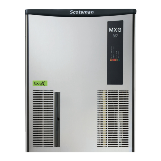
MXG 327
MXG 427
MXG 437
modular cubers
Scotsman Ice Srl
Via Lainate, 31 - 20010 Pogliano M.se - Milano - Italy
Tel. +39-02-93960.1 (Aut. Sel.)- Telefax +39-02-93550500
Direct Line to Service & Parts:
Phone +39-02-93960350 - Fax +39-02-93540449
Website: www.scotsman-ice.it
E-Mail: scotsman.europe@scotsman.it
SERVICE MANUAL
R 290
Electronic
Page 1
REV. 07/2018
Advertisement
Table of Contents

Related Manuals for Scotsman MXG 327


Summary of Contents for Scotsman MXG 327
- Page 1 Page 1 Page 1 SERVICE MANUAL MXG 327 MXG 427 MXG 437 R 290 Electronic modular cubers Scotsman Ice Srl Via Lainate, 31 - 20010 Pogliano M.se - Milano - Italy Tel. +39-02-93960.1 (Aut. Sel.)- Telefax +39-02-93550500 Direct Line to Service & Parts: Phone +39-02-93960350 - Fax +39-02-93540449 Website: www.scotsman-ice.it...
- Page 2 PC BOARD 620462 06/11 – NEW RELEASE – NUOVELLE VERSION – NUOVA VERSIONE STATUS REASON WHY-SIGNIFICATION-SIGNIFICATO ON STEADY UNIT UNDER POWER FIXE SOUS TENSION FISSO IN TENSIONE ON STEADY FREEZING CYCLE FIXE EN RÉFRIGÉRATION FISSO IN CONGELAMENTO BLINKING 60 MINUTES DELAY AT START UP – JUMPER J3 OUT CLIGNOTANT 60 MINUTES DE RETARD AU DEMARRAGE –...
-
Page 3: Table Of Contents
Page 2 Page 2 TABLE OF Table of contents CONTENTS Specifications MXG 327 Specifications MXG 427 Specifications MXG 437 GENERAL INFORMATION AND INSTALLATION Introduction Unpacking and Inspection - Ice maker Unpacking and Inspection - Storage bin Location and levelling Electrical connections... -
Page 4: Page
Page 3 Page 3... - Page 5 NOTE. The daily ice-making capacity is directly related to the condenser air inlet temperature, water temperature and age of the machine. To keep your SCOTSMAN MODULAR CUBER at peak performance levels, periodic maintenance checks must be carried out as indicated on maintenance section of this manual.
- Page 6 Page 4 Page 4 SPECIFICATIONS MXG 327 - MACHINE SPECIFICATIONS Model Cond. unit Finish Water req. - lt/24 HR MXG 327 AS 6 Stainless steel 480* MXG 327 WS 6 Water Stainless steel Starts Electric power cons. Basic electr. Amps Watts N.
- Page 7 NOTE. The daily ice-making capacity is directly related to the condenser air inlet temperature, water temperature and age of the machine. To keep your SCOTSMAN MODULAR CUBER at peak performance levels, periodic maintenance checks must be carried out as indicated on maintenance section of this manual.
- Page 8 Page 6 Page 6 SPECIFICATIONS MXG 427 - MACHINE SPECIFICATIONS Model Cond. unit Finish Water req. - lt/24 HR MXG 427 AS 6 Stainless steel 432* MXG 427 WS 6 Water Stainless steel Starts Electric power cons. Basic electr. Amps Watts N.
- Page 9 NOTE. The daily ice-making capacity is directly related to the condenser air inlet temperature, water temperature and age of the machine. To keep your SCOTSMAN MODULAR CUBER at peak performance levels, periodic maintenance checks must be carried out as indicated on maintenance section of this manual.
- Page 10 Page 8 Page 8 SPECIFICATIONS MXG 437 - MACHINE SPECIFICATIONS Model Cond. unit Finish Water req. - lt/24 HR MXG 437 AS 6 Stainless steel 432* MXG 437 WS 6 Water Stainless steel Starts Electric power cons. Basic electr. Amps Watts N.
-
Page 11: General Information And Installation
Forward the completed self-addressed SB 193 registration card to Scotsman Ice srl. SB 322 SB 393 SB 530. C. LOCATION AND LEVELLING UNPACKING AND INSPECTION WARNING. -
Page 12: Electrical Connections
All SCOTSMAN icemakers require a solid earth wire. Place the Modular Cuber on top of All SCOTSMAN ice machines are supplied from Storage bin using care not to wrinkle or tear the factory completely pre-wired and require only the gasket. -
Page 13: Final Check List
Page 11 Page 11 Water drain Is there at least a 15 cm (6") clearance around the unit for proper air circulation? The recommended drain tube is a plastic or flexible tube with 18 mm (3/4") I.D. which runs to Is the unit level? (IMPORTANT) an open trapped and vented drain. -
Page 14: Operating Instructions
Page 12 Page 12 OPERATING INSTRUCTIONS sump reservoir to fill it up and also that the START UP incoming surplus of water flows out through the After having correctly installed the ice maker and overflow pipe into the drain line. completed the plumbing and electrical During the water filling phase the components connections, perform the following “Start-up”... -
Page 15: Operatiobnal Checks
Page 13 Page 13 At completion of the water filling phase (5 After having diagnosed the reason of the rise minutes) the unit passes automatically into the of temperature and removed its cause, it is freezing cycle with the start up of: necessary to unplug (wait few seconds) and COMPRESSOR plug in again the unit, thus to put the... - Page 16 Page 14 Page 14 FIG. 3 WATER DRAIN VALVE - EVAPORATOR WATER IN VALVE SWITCH - CONDENSER ELECTR. HOT GAS VALVE TIMER - AMBIENT CONTACTOR COIL RELAYS FAN MOTOR TRIAC TRANSF. WATER PUMP RELAY ELECTRONIC CARD FIG. 4 WATER DRAIN VALVE - EVAPORATOR WATER IN VALVE SWITCH...
- Page 17 Page 15 Page 15 During the freezing process, when the evaporator After about 17-20 minutes from the temperature falls below an established value, to beginning of the freezing cycle, in an hypothetic the evaporator temperature sensor supplies a ambient temperature of 21°C , the defrost cycle low voltage power signal to the electronic control takes place with the hot gas and the water inlet device (P.C.BOARD) in order to activate an...
- Page 18 Page 16 Page 16 the ice maker resume its operation with the Check the texture of ice cubes just released. immediate glowing of the FIRST YELLOW LED They have to be in the right shape with a small indicating UNIT IN OPERATION and the depression of about 5-6 mm in their crown.
-
Page 19: Freezing Cycle
The vapor refrigerant then passes through the How it works suction accumulator (used to prevent that any In the SCOTSMAN Modular Cubers the water small amount of liquid refrigerant may reach the used to make the ice is kept constantly in compressor) and through the suction line. - Page 20 Page 18 Page 18...
-
Page 21: Harvest Cycle
Page 19 Page 19 it causes the total and immediate SHUT-OFF ATTENTION. In case, after 15 minutes from the beginning of the freezing cycle, of the machine in order to prevent the unit the temperature of the evaporator sensor from operating in abnormal and dangerous probe is higher then 0°C (32°F) (shortage conditions. -
Page 22: Control Sequence
Page 20 Page 20 The incoming water, passing through the water Electronic Controls & Sensors .. ON OFF inlet valve and the flow control, runs over the • Evaporator Sensor ....... evaporator platen and then flows by gravity • Condenser Sensor ....... through the dribbler holes down into the sump/ •... -
Page 23: Component Description
REF. CHARGE at 21°C amb. / 15°C water MODEL VOLTAGE CUBE SIZE (R290 - gr.) suction discharge (beg./end freez.) MXG 327 A 230/50/1 2,8 / 1 10 - 13,5 MXG 327 W 230/50/1 MXG 427-437 A 230/50/1 1,9 / 0,7... - Page 24 Page 22 Page 22 In case the condenser temperature rises and NOTE. The setting of the Ice Level Control reaches 70°C (1 60°F) - on air cooled models - or Sensivity must be done any time a new PC 62°C (145°F) - on water cooled models - the Board or a new lce Level Control is installed current arriving to the micro processor is such to in the machine.
- Page 25 Page 23 Page 23 At restart, from any tripping OFF at Bin Full, the new PC Board assures 45 seconds water filling The length of Harvest is equal to: phase so to refill the water sump up to the maximum level. •35”...
- Page 26 Page 24 Page 24 DIP SWITCH REASON WHY STATUS The P.C.BOARD which controls the entire operation of the ice maker, has a DIP SWITCH with ten switching keys which allow to set up ON STEADY UNIT UNDER POWER the micro processor program in order to extend or to shorten the length of freezing cycle in relation to the different model and versions of ice machines.
- Page 27 Page 25 Page 25 The 9th key is used to supply power to the water Located on the hot gas line, this valve is energized pump for the first 15 seconds of the defrost cycle through the micro processor of P.C. BOARD - position OFF - or for the first 30 seconds - during the defrost cycle and as well during the position ON.
-
Page 28: Adjustment, Removal And Replacement Procedures
Page 26 Page 26 ADJUSTMENT, REMOVAL AND REPLACEMENT PROCEDURES ADJUSTMENT OF THE CUBE SIZE CAUTION. Before performing actual adjustment of the cube size, check other possible causes for cube size problems, refer to the Service Diagnosis Section for problem review and analysis. Do not perform any adjustment till the icemaking system has progressed SMALL... -
Page 29: Wiring Diagram
Page 27 Page 27 WIRING DIAGRAM MXG 327 - 427 - 437 A 230/50/1... - Page 30 Page 28 Page 28...
-
Page 31: Service Diagnosis
Shortage of water See remedies for shortage of water Dirty water supply Use water softner or water filter Accumulated impurities Use SCOTSMAN Ice Machine cleaner Shortage of water Water spilling out through curtain Check or replace curtain Water solenoid valve not opening... - Page 32 Page 30 Page 30 SERVICE DIAGNOSIS SYMPTON POSSIBLE CAUSE SUGGESTED CORRECTION Irregular cubes size & some Some jets plugged Remove spray bar & jet bearing cloudy and clean them Shortage of water See shortage of water Unit not level Level as required Spray bar not rotating Remove spray bar &...
-
Page 33: Maintenance And Cleaning Instructions
Perform adjustment of DIP SWITCH keys Clean the water system, evaporators, bin as required. and spray bar/s using a solution of SCOTSMAN Ice Machine Cleaner. Check the ice level control sensor to test Refer to procedure C cleaning instructions and shut-off. -
Page 34: Cleaning Instructions Of Water System
Cleaning Mode (Fig.7) cleaning solution by diluting in a plastic container two or three liters of warm water (45°-50°C) with a 0,2-0,3 liters of SCOTSMAN Ice Machine Cleaner. WARNING. The SCOTSMAN Ice Machine Cleaner contains Phosphoric and Hydroxyacetic acids. - Page 35 Page 33 Page 33 14. Flush out the rinsing solution from the sump With the system in Cleaning mode the reservoirs water pump is the only component in operation to circulate the cleaning solution in the entire 15. Place again the evaporator cover and the water system unit service panels.
- Page 36 Page 34 Page 34 Sanitation 22. At completion of the freezing and harvest cycle make sure of proper texture and clearness of the ice cubes and that, they do not have any acid taste. NOTE. Sanitation of the water system is recommended to be done once a month.