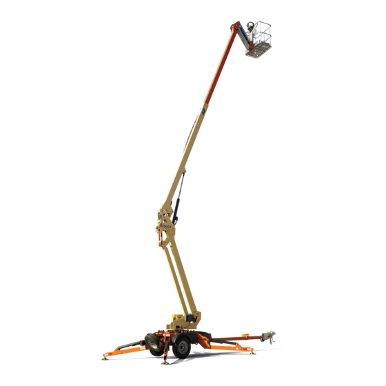
JLG T500J Service And Maintenance Manual
Hide thumbs
Also See for T500J:
- Operation and safety manual (132 pages) ,
- Service and maintenance manual (230 pages) ,
- Troubleshooting manual (225 pages)

Related Manuals for JLG T500J


Summary of Contents for JLG T500J
- Page 1 Service and Maintenance Manual Model T500J PN -3121200 July 25, 2018 - Rev I AS/NZS...
-
Page 3: General
INTRODUCTION SECTION A. INTRODUCTION - MAINTENANCE SAFETY PRECAUTIONS GENERAL MAINTENANCE This section contains general safety precautions which must be observed during aerial platform maintenance. It is of utmost importance that maintenance personnel pay strict FAILURE TO COMPLY WITH SAFETY PRECAUTIONS LISTED IN THIS SECTION attention to these warnings and precautions to avoid possible COULD RESULT IN MACHINE DAMAGE, PERSONNEL INJURY OR DEATH AND IS A injury to themselves or others, or damage to the equipment. - Page 4 INTRODUCTION REVISON LOG A - January 15, 2005 Original Issue B - July 15, 2005 Revised C - August 26, 2005 Revised D - December 12, 2005 Revised E - February 24, 2006 Revised F - May 1, 2007 Revised G - September 28, 2011 Revised H - January 9, 2013...
-
Page 5: Table Of Contents
Do Not Do The Following When Welding On Jlg Equipment ....... - Page 6 TABLE OF CONTENTS SECTION NO. TITLE PAGE NO. SECTION 3 - CHASSIS & TURNTABLE Breaking-in a New Trailer ................3-1 Retighten Lug Nuts at First 10, 25 &...
- Page 7 TABLE OF CONTENTS SECTION NO. TITLE PAGE NO 3.12 Trailer Jack..................3-36 Installation.
- Page 8 TABLE OF CONTENTS SECTION NO. TITLE PAGE NO. 3.26 Battery Charger (Prior to S/N 030000236)............3-104 Removal .
- Page 9 To Connect the JLG Control System Analyzer........
- Page 10 TABLE OF CONTENTS SECTION NO. TITLE PAGE NO. SECTION 7 - BASIC ELECTRICAL INFORMATION & SCHEMATICS General ................... . 7-1 Multimeter Basics .
- Page 11 LIST OF FIGURES FIGURE NO. TITLE PAGE NO. 1-1. Operator Maintenance & Lubrication Diagram ............1-4 1-2.
- Page 12 LIST OF FIGURES FIGURE NO. TITLE PAGE NO. 5-1. Cylinder Locations - Sheet 1 of 2 ..............5-3 5-2.
- Page 13 LIST OF FIGURES FIGURE NO. TITLE PAGE NO. 5-58. Machine - Sheet 1 of 12 ................5-48 5-59.
- Page 14 LIST OF FIGURES FIGURE NO. TITLE PAGE NO. 7-32. Controller and Valve Body Connector Locations - Engine Machine without Drive ..... 7-22 7-33.
- Page 15 LIST OF TABLES TABLE NO. TITLE PAGE NO. Operating & Towing Specifications ..............1-1 Dimensional Data .
-
Page 16: Table No
LIST OF TABLES TABLE NO. TITLE PAGE NO. This page left blank intentionally. 3121200... -
Page 17: Specifications
SECTION 1 - SPECIFICATIONS SECTION 1. SPECIFICATIONS OPERATING SPECIFICATIONS DIMENSIONAL DATA Table 1-1. Operating & Towing Specifications Table 1-2. Dimensional Data Tongue Weight (ANSI): Overall Length 350 lbs.(154 kg) Note: Tongue weight may increase with options. Surge Brake, 2" ball/50mm ball 27 ft 4 in (8.33 m) Electric Brake, 2"... -
Page 18: Electric Power Unit
SECTION 1 - SPECIFICATIONS ELECTRIC POWER UNIT ENGINE Table 1-4. Electric Power Unit Specifications Table 1-6. Engine Specifications Type 4-stroke, overhead valve, single cylinder @ 740PSI @1500PSI @ 3000PSI (51 Bar) (103 Bar) (207 Bar) Displacement 16.5 cu.in. (270 cm³) Power 3.0 kW 3.0 kW... -
Page 19: Lubrication
Platform w/Rotator Platform W/o Rotator NOTE: Aside from JLG recommendations, it is not advisable to mix oils of different brands or types, as they may not contain the same required additives or be of comparable viscosi- 1.11 PRESSURE SETTINGS... -
Page 20: Operator Maintenance & Lubrication Diagram
SECTION 1 - SPECIFICATIONS 10,11 MAE29490 Figure 1-1. Operator Maintenance & Lubrication Diagram 3121200... -
Page 21: Maintenance & Lubrication
SECTION 1 - SPECIFICATIONS 1.12 MAINTENANCE & LUBRICATION Hydraulic Oil NOTE: Lubrication intervals are based on machine operation under normal conditions. For machines used in multi shift operations and/or exposed to hostile environments or con- ditions, lubrication frequencies must be increased accord- ingly. - Page 22 SECTION 1 - SPECIFICATIONS Swing Bearing Engine Lube Point(s) - 1 Grease Fitting Capacity - See Engine Manual. Capacity - As Required Lube - EO, 10W30 API SJ Interval - Check level daily; change per Lube - MPG Interval - Every month or 50 hours manufacturer’s engine manual....
- Page 23 SECTION 1 - SPECIFICATIONS Trailer Jack Coupler & Hitch Ball GREASE Capacity - Coupler 2 Grease Fittings (CE Only); Hitch Ball As necessary Lube - MPG Interval - As necessary. Jockey Wheel Bearing (Drive and Set Option Only) Capacity - As necessary Lube - MPG &...
-
Page 24: Torque Chart (Sae Fasteners - Sheet 1 Of 5)
SECTION 1 - SPECIFICATIONS Figure 1-2. Torque Chart (SAE Fasteners - Sheet 1 of 5) 3121200... -
Page 25: Torque Chart (Sae Fasteners - Sheet 2 Of 5)
SECTION 1 - SPECIFICATIONS Figure 1-3. Torque Chart (SAE Fasteners - Sheet 2 of 5) 3121200... -
Page 26: Torque Chart (Sae Fasteners - Sheet 3 Of 5)
SECTION 1 - SPECIFICATIONS Figure 1-4. Torque Chart (SAE Fasteners - Sheet 3 of 5) 1-10 3121200... -
Page 27: Torque Chart (Sae Fasteners - Sheet 4 Of 5)
SECTION 1 - SPECIFICATIONS Figure 1-5. Torque Chart (SAE Fasteners - Sheet 4 of 5) 3121200 1-11... -
Page 28: Torque Chart (Metric Fasteners - Sheet 5 Of 5)
SECTION 1 - SPECIFICATIONS Figure 1-6. Torque Chart (METRIC Fasteners - Sheet 5 of 5) 1-12 3121200... -
Page 29: General
Service Technician as a person who has successfully com- care, maintenance and inspections performed per JLG's rec- pleted the JLG Service Training School for the subject JLG ommendations with any and all discrepancies corrected, this product model. Reference the machine Service and Mainte- product will be fit for continued use. -
Page 30: Service And Guidelines
Pre-Delivery Inspection Owner, Dealer, or User Qualified JLG Mechanic Service and Maintenance Manual rental delivery. and applicable JLG inspection form. Frequent Inspection In service for 3 months or 150 hours, whichever Owner, Dealer, or User Qualified JLG Mechanic Service and Maintenance Manual comes first;... -
Page 31: Component Disassembly And Reassembly
SECTION 2 - GENERAL Component Disassembly and Reassembly Bolt Usage and Torque Application When disassembling or reassembling a component, complete the procedural steps in sequence. Do not partially disassemble or assemble one part, then start on another. Always recheck SELF LOCKING FASTENERS, SUCH AS NYLON INSERT AND THREAD DEFORMING your work to assure that nothing has been overlooked. -
Page 32: Lubrication
When recommended lubricants are not avail- JLG recommends Mobilfluid 424 hydraulic oil, which has able, consult your local supplier for an equivalent that meets an SAE viscosity of 10W-30 and a viscosity index of 152. -
Page 33: Cylinder Drift
SECTION 2 - GENERAL CYLINDER DRIFT Cylinder Leakage Test Cylinder oil must be at stabilized ambient temperature before Theory beginning this test. When a hydraulic cylinder is supporting a load, cylinder drift Measure drift at cylinder rod with a calibrated dial indicator. may occur as a result of any of the circumstances below: In an area free of obstructions, cylinder must have load •... -
Page 34: Pins And Composite Bearing Repair Guidelines
Filament wound bearings should be replaced if any of • Ground only to structure being welded. the following is observed: • Unplug all pressure transducers Refer to Section 6 - JLG a. Frayed or separated fibers on the liner surface. Control System. -
Page 35: Maintenance Schedule
SECTION 2 - GENERAL Table 2-3. Maintenance Schedule INTERVAL Every 3000 Miles Every 6000 Miles Every 12,000 Item/Function Method Break-In or 3 Months or 6 Months Miles or 1 year Tighten to specified torque rating Wheel Lugs Coupler Ball Check for unusual wear Safety Chains Check for unusual wear in links Check general operation and proper adjustment... - Page 36 SECTION 2 - GENERAL NOTES: 3121200...
-
Page 37: Chassis & Turntable
3000 miles intervals, (3) or as use and performance requires. turers’ instructions. If you do not have these instructions, call your dealer or JLG to obtain a copy. A hard stop is used to: • Confirm that the brakes work •... -
Page 38: Manually Adjusting Brake Shoes
SECTION 3 - CHASSIS & TURNTABLE Manually Adjusting Brake Shoes ELECTRIC BRAKES The manually adjusted brakes should be adjusted in the fol- The electric brakes on a trailer are similar to the drum brakes lowing manner: on an automobile. The basic difference is that the automotive brakes are actuated by hydraulic pressure while electric trailer 1. -
Page 39: Brake Controller
SECTION 3 - CHASSIS & TURNTABLE Brake Controller HYDRAULIC (SURGE) BRAKES A tow vehicle brake controller is required. These controllers In the hydraulic brake system, hydraulic fluid from the master have gain control to vary the amount of current to the brakes, cylinder is used to actuate the hydraulic wheel cylinder, which, and a level control which sets the controller's inertia sensor to in turn, applies force against the brake shoes and drum. -
Page 40: Self Adjusting Mechanism
SECTION 3 - CHASSIS & TURNTABLE Self Adjusting Mechanism General Maintenance The self adjusting feature adjusts the brakes on both forward DRUM BRAKE ADJUSTMENT and reverse stops. Brake adjustment occurs only when lining Brakes should be adjusted (1) after the first 200 miles of opera- wear results in enough gap between the shoes and the drum tion when the brake shoes and drums have “seated, ”... -
Page 41: Mechanical Brake
SECTION 3 - CHASSIS & TURNTABLE MECHANICAL BRAKE REPLACING BRAKE SHOES Place the trailer on stands with all wheels off of the ground. Brake Maintenance WARNING: The handbrake should be released and the hand- brake locking bolt installed. WHEEL BRAKES The linings of the wheel brakes are wearing parts, so their con- dition must be checked every 3000 miles (5000 km) or every year, whichever comes first, using the view holes on the wheel... -
Page 42: Mechanical Brake Assembly
SECTION 3 - CHASSIS & TURNTABLE 1. Flanged Nut 7. Castle Nut 13. Tension Spring (Bottom) 19. Adjusting Bolt 2. Lockwasher 8. Inner Bearing 14. Tension Spring (Top) 20. Bolt 3. Hub/Drum Assembly 9. Outer Bearing 15. Tension Spring (Center) 21. - Page 43 SECTION 3 - CHASSIS & TURNTABLE 7. Undo the locknut on the brake rod (front to rear) adja- ADJUSTMENT cent to the compensator. Slacken the second nut on the NOTE: When adjusting the brake drum, only turn the wheel in the brake rod.
-
Page 44: Adjustment And Readjustment Of The Overrun Braking System
SECTION 3 - CHASSIS & TURNTABLE Adjustment and Readjustment of the Overrun ADJUSTMENT PROCEDURE Braking System 1. Brake a. Loosen the linkage ADJUSTING THE BRAKING SYSTEM b. Tighten the adjusting screw (12) (on the outside of Preparations: the brake plate, opposite the cable entry[13]), turn- ing clockwise until the wheel can only be turned 1. - Page 45 SECTION 3 - CHASSIS & TURNTABLE 2. Brake Compensating System READJUSTING THE BRAKING SYSTEM The main purpose of readjusting the braking system is com- a. Preadjust the length of the brake linkage (slight play pensate for brake lining wear. To readjust the wheel brakes, permitted).
-
Page 46: Troubleshooting
SECTION 3 - CHASSIS & TURNTABLE Troubleshooting Table 3-1. Malfunctions and Remedies Malfunction Cause Remedy Insufficient braking effect Excessive backlash in brake system Service at qualified workshop Brake linings not run in Actuate hand-brake lever slightly; drive 1-2 miles (2-3 km) Brake linings glazed, oily or damaged Service at qualified workshop Overrunning hitch hard to operate... -
Page 47: Axle And Tongue Installation With Electric Brakes (2 In Ball)
SECTION 3 - CHASSIS & TURNTABLE BRAKE LEVER 2in Ball 0273654-I MAE30540 * Torque to 120-155 ft. lbs (160-210 Nm) 1. Safety Chain 5. Parking Brake Bracket 9. Tongue Adapter 2. Pin and Cable 6. Conduit 10. Battery Charger 3. Coupler Assembly 7. -
Page 48: Axle And Tongue Installation With Electric Brakes (50Mm Ball)
SECTION 3 - CHASSIS & TURNTABLE BRAKE LEVER 50mm Ball * Torque to 120-155 ft. lbs (160-210 Nm) 0274767-C MAE30620 1. Coupler assembly 6. Parking Brake Bracket 2. Spacer 7. Conduit 3. Pin and cable 8. Electric Brake Assembly 4. Tongue 9. -
Page 49: Axle And Tongue Installation With Hydraulic Brakes (2In Ball)
SECTION 3 - CHASSIS & TURNTABLE 2 in Combination BRAKE LEVER * Torque to 120-155 ft. lbs (160-210 Nm) 2 in Ball 0275908-E MAE30550 1. Safety Chain 5. Tongue Adapter 9. Hydraulic Brake Assembly 2. Coupler Assembly 6. Parking Brake Cable Assembly 10. -
Page 50: Axle And Tongue Installation With Mechanical Brakes (50Mm Ball)
SECTION 3 - CHASSIS & TURNTABLE * Torque to 120-155 ft. lbs (160-210 Nm) 0273657-G MAE30560 1. Hitch Adapter 3. Tongue 5. Brake Rod Support 7. Mechanical Brake Assembly 2. Coupler Assembly 4. Rod 6. Tube Mount Bar 8. Tire Assembly Figure 3-10. -
Page 51: Hubs, Drums, Wheel Bearings
SECTION 3 - CHASSIS & TURNTABLE HUBS, DRUMS, WHEEL BEARINGS Bearing Inspection Wash all grease and oil from the bearing cone using a suitable The wheel bearing configuration consists of opposed tapered solvent. Dry the bearing with a clean, lint-free cloth and roller bearing cones and cups, fitted inside of a precision inspect each roller assembly. -
Page 52: Seal Inspection And Replacement
SECTION 3 - CHASSIS & TURNTABLE 2. Press a section of the widest end of the bearing into the 1. Pry the seal out of the hub with a screwdriver. Never outer edge of the grease pile closest to the thumb forc- drive the seal out with the inner bearing as you may ing grease into the interior of the bearing. -
Page 53: Hub And Brake Assembly
SECTION 3 - CHASSIS & TURNTABLE 1. Grease Seal 5. Hub Assembly 9. Spindle Washer 13. Wheel Nut 2. Inner Bearing Cone 6. Wheel Stud 10. Spindle Nut 14. Hub 3. Inner Bearing Cup 7. Outer Bearing Cup 11. Cotter Pin 4. -
Page 54: Tires & Wheels
SECTION 3 - CHASSIS & TURNTABLE WHEEL CYLINDERS TIRES & WHEELS Inspect for leaks and smooth operation. Clean with brake cleaner and flush with fresh brake fluid. Hone or replace as Tire Inflation necessary. Tire pressure is the most important factor in tire life. Inflation BRAKE LINES pressure should be as recommended and stated on the side- Check for cracks, kinks, or blockage. -
Page 55: Tire Replacement
JLG recommends a replacement tire be the same size, ply and brand as originally installed on the machine. Please refer to the JLG Parts Manual for the part number of the approved tires for a particular machine model. If not using a JLG approved... -
Page 56: Spare Tire (Optional)
SECTION 3 - CHASSIS & TURNTABLE PLACE THE SPARE ON THE HOOK PROVIDED ON THE MOUNTING FIXTURE AND THEN FOLLOW DIRECTOINS BELOW ROTATE THE SPARE SO THE TWO HOLES LINE UP WITH THE TWO SLOTS IN THE MOUNTING PLATE AND INSERT CARRIAGE BOLTS THROUGH FROM THE BACK SIDE. -
Page 57: Hydraulic Brake Coupler
SECTION 3 - CHASSIS & TURNTABLE HYDRAULIC BRAKE COUPLER Troubleshooting IF ANY OF THE FOLLOWING CONDITIONS DEVELOP, TRAILER MUST NOT BE USED UNTIL PROPER CORRECTIVE ACTION IS TAKEN. Table 3-5. Surge Brake Troubleshooting Symptom Cause Solution Squeaking, Clatter, or Chucking Lack of Hitch Ball Lubrication Lubricate with conventional automotive grease or commercial lubricant made for hitch balls... -
Page 58: Bleeding The Brake System
SECTION 3 - CHASSIS & TURNTABLE Bleeding the Brake System Towing DO NOT USE BRAKE FLUID DRAINED FROM THE BRAKE SYSTEM IN REFILLING THE TRAILER MAY DISCONNECT IF NOT PROPERLY SECURED. THE RELEASE THE MASTER CYLINDER. USED BRAKE FLUID CAN BE CONTAMINATED FROM HANDLE MUST BE FULLY CLOSED BEFORE TOWING. - Page 59 SECTION 3 - CHASSIS & TURNTABLE 3. Lower trailer tongue until ball rests in ball socket. 4. Close the release handle. The release handle will close DO NOT USE THE BREAKAWAY CABLE AS A PARKING BRAKE. freely with finger pressure when the ball is properly inserted into the ball socket.
-
Page 60: Backing Up
SECTION 3 - CHASSIS & TURNTABLE Backing Up NOTE: Lubricate the hitch ball with conventional automotive grease or a lubricant made for hitch balls. 1. Follow steps 1 thru 13 under Towing. 2. Check for leaks in the brake system. Periodic checks should be made on all hoses and fittings to guard 2. -
Page 61: Hydraulic Brake Coupler With 2In Ball - Prior To Sn 0030002099
SECTION 3 - CHASSIS & TURNTABLE 1. Not Used 7. Gasket 13. Spring 19. Not Used 25. Block 31. Shipping Plug 2. Not Used 8. Boot 14. Bolt 20. Bolt 26. Bushing 32. Not Used 3. Push Rod 9. Stop 15. -
Page 62: Combination Coupler
SECTION 3 - CHASSIS & TURNTABLE COMBINATION COUPLER General Maintenance 1. Frequently check brake fluid level. Fluid must be approved, clean, and uncontaminated. THE WEIGHT RATING OF THE COUPLER IS DEPENDENT UPON THE CORRECT 2. Make sure actuator mounting bolts are secure. BOLTS BEING USED. -
Page 63: Hydraulic Brake Coupler With Combination 2In Ball - Prior To Sn 0030002099
SECTION 3 - CHASSIS & TURNTABLE 1. Not Used 7. Outer Case 13. Bolt 19. Nut 25. Pin 2. Not Used 8. Lockwasher 14. Bolt 20. Gasket 26. Upper Slider 3. Not Used 9. Cotter Pin 15. Lockwasher 21. Reservoir 27. -
Page 64: Coupler Assembly (Sn 0030002099 To Present)
SECTION 3 - CHASSIS & TURNTABLE 3.10 COUPLER ASSEMBLY (SN 0030002099 TO Servicing the Breakaway Assembly PRESENT) A thorough inspection of the breakaway assembly is required if it is applied at any time. Damaged parts must be replaced. If Engaging Manual Lockout Lever there is any damage to the lanyard itself the entire pushrod assembly will need to be replaced. -
Page 65: Hydraulic Brake Coupler With Combination 2 In Ball - Sn 0030002099 Through Present
SECTION 3 - CHASSIS & TURNTABLE SN 0030002099 THROUGH 0030003342 SN 0030003342 TO PRESENT MAE29550 1. Coupler 7. Pin 13. Reservoir 19. Damper Shock 2. Emergency Lever Guide 8. Outer Case 14. Push Rod 20. Upper Slider 3. Emergency Lever Spring Plate 9. -
Page 66: Actuator Maintenance
SECTION 3 - CHASSIS & TURNTABLE Actuator Maintenance 2. Maintain a film of oil on the pivot points and safety latch spring using SAE 30W motor oil. 1. Frequently check brake fluid level (fluid must be DOT3 or 4 approved, clean and uncontaminated). 2. -
Page 67: Hitch Coupler & Axle (Ce Only)
Maintenance, repairs, and replacement of wearing parts for the chassis and the braking system may only per- formed by a qualified garage. Only original JLG parts may be used in order to: • ensure proper functioning and safety • preserve all rights under warranty •... - Page 68 SECTION 3 - CHASSIS & TURNTABLE The position of the coupling point on the trailer must be in a range of 430 ± 35 mm above the horizontal tire contact sur- face. IF THE INDICATOR IS IN THE RED "-" ZONE, THE COUPLING IS NOT PROPERLY CLOSED, AND THE TRAILER MUST NOT BE TOWED! To check the coupling height, the trailer and towing vehicle must be exactly horizontal and fully loaded to make up the...
-
Page 69: Coupling Head Maintenance
SECTION 3 - CHASSIS & TURNTABLE Coupling Head Maintenance 9. If the damper has been released the rear mounting bracket will need to be re-fitted. This means that the damper needs to be compressed so the bolts can be REPLACING installed. -
Page 70: Damper Maintenance
SECTION 3 - CHASSIS & TURNTABLE Damper Maintenance c. Knock out the retaining pin and remove the rear bolt, this will allow the damper to move forward and The dampers assembled within the overrun coupling is pres- contact the front bolt. surized. -
Page 71: Hydraulic Brake Coupler (Ce And Csa Spec Machines)
SECTION 3 - CHASSIS & TURNTABLE 17 16 1660283-D MAE30680 1. Coupling Head 5. Stop Ring 9. Handbrake Lever 2. Gas Spring 6. Housing 10. Cable 3. Bellow 7. Gas Mounting Spring 11. Transmission Lever 4. Draw Tube 8. Handle 12. -
Page 72: 3.12 Trailer Jack
SECTION 3 - CHASSIS & TURNTABLE 3.12 TRAILER JACK Installation 1. Place the jack against the trailer tongue and position the mounting straps on the opposite side of the tongue. Place the straps so the flat side is against the tongue. 2. -
Page 73: Assembly
SECTION 3 - CHASSIS & TURNTABLE Assembly CASTER WHEEL 1. Grease the outside of the wheel spacer using standard HANDLE automotive grease and insert it into the wheel. 2. Place the wheel and spacer into the yoke and align the holes in the wheel with the holes in the yoke. -
Page 74: Swing Motor (Prior To S/N 0030000960)
SECTION 3 - CHASSIS & TURNTABLE 7. Remove the drive link pin and drive link from the motor 3.13 SWING MOTOR (PRIOR TO S/N 0030000960) and lay aside. 8. Gently tap the shaft upward through the housing and NOTE: This motor may also be used on some machines manufac- remove through the rear of the housing. -
Page 75: Assembly
SECTION 3 - CHASSIS & TURNTABLE Assembly Shaft Timing Procedure FOR PROPER OPERATION, THE MOTOR DEPENDS ON THE CORRECT ORIENTA- FOR PROPER OPERATION, THE MOTOR DEPENDS ON THE CORRECT ORIENTA- TION OF PARTS AS WELL AS THE CORRECT INTERNAL TIMING. TION OF PARTS AS WELL AS THE CORRECT INTERNAL TIMING. -
Page 76: Installation
SECTION 3 - CHASSIS & TURNTABLE 10. Place a body seal in the grove in the face of the rotor. Installation 11. Lower the rotor onto the drive link making sure the tim- 1. Connect the two hydraulic lines to the motor as tagged ing mark on the drive link is aligned with a peak on the during Removal. -
Page 77: Swing Motor
SECTION 3 - CHASSIS & TURNTABLE 1. Dust Seal 6. Shaft Seal 11. Ball 16. Drive Link Pin 2. Retainer Ring 7. Thrust Washer 12. Cooling Plug 17. Bolt 3. Backup Shim 8. Thrust Bearing 13. Housing 18. Shaft 4. Housing Seal 9. -
Page 78: Swing Motor (Sn 0030001051 To Present)
SECTION 3 - CHASSIS & TURNTABLE 3.14 SWING MOTOR (SN 0030001051 TO PRESENT) 2. Scribe an alignment mark down and across the Torq- NOTE: This motor may also be used on some machines manufac- link™ components from end cover (2) to housing (18) to tured between S/N 0030000960 to 0030001050. -
Page 79: Swing Drive Motor
SECTION 3 - CHASSIS & TURNTABLE 1. Special Bolts 8B. Stator or Stator Vane 16. Seal 2. End Cover 8C. Vane 17. Back-up Washer 18. Housing 3. Seal Ring-Commutator 8D. Stator Half 4. Seal Ring 9. Wear Plate 18A. O-Ring 5. - Page 80 SECTION 3 - CHASSIS & TURNTABLE 4. Remove end cover assembly (2) and seal ring (4). Discard 6. Thoroughly wash end cover (2) in proper solvent and seal ring. blow dry. Be sure the end cover valve apertures, includ- ing the internal orifice plug, are free of contamination. Inspect end cover for cracks and the bolt head recesses for good bolt head sealing surfaces.
- Page 81 SECTION 3 - CHASSIS & TURNTABLE 8. Remove commutator (5) and seal ring (3) Remove seal NOTE: The manifold is constructed of plates bonded together to ring from commutator, using an air hose to blow air into form an integral component not subject tofurtherdisas- ring groove until seal ring is lifted out and discard seal semblyforservice.Compare configuration of both sides oft ring.
- Page 82 SECTION 3 - CHASSIS & TURNTABLE NOTE: Series TG Torqlinks™ may have a rotor set with two stator 13. Remove thrust bearing (11) from top of coupling shaft halves (8B) with a seal ring (4) between them and two sets (12).
- Page 83 SECTION 3 - CHASSIS & TURNTABLE 15. Remove coupling shaft (12), by pushing on the output Remove seal (16) and back up washer (17) from Small end of shaft. Inspect coupling shaft bearing and seal sur- Frame, housing (18). Discard both. faces for spalling, nicks, grooves, severe wear or corro- sion and discoloration.
- Page 84 SECTION 3 - CHASSIS & TURNTABLE 20. Inspect housing (18) assembly for cracks, the machined surfaces for nicks, burrs, brinelling or corrosion. Remove burrs that can be removed without changing dimen- sional characteristics. Inspect tapped holes for thread damage. If the housing is defective in these areas, dis- card the housing assembly.
-
Page 85: Assembly
SECTION 3 - CHASSIS & TURNTABLE 22. If the bearings, bushing or thrust washers must be Assembly replaced use a suitable size bearing puller to remove bearing/bushings (19) and (13) from housing (18) with- Replace all seals and seal rings with new ones each time you out damaging the housing. - Page 86 SECTION 3 - CHASSIS & TURNTABLE 2. The Torqlink™ inner housing bearing/bushing (13) can now be pressed into its counterbore in housing (18) flush to 0.03 inch (0.76 mm) below the housing wear plate contact face. Use the opposite end of the bearing mandrel that was used to press in the outer bearing/ bushing (19).
- Page 87 SECTION 3 - CHASSIS & TURNTABLE 4. Place housing (18) assembly into a soft jawed vise with the coupling shaft bore down, clamping against the mounting flange. 3. Press a new dirt and water seal (20) into the housing (18) outer bearing counterbore.
- Page 88 SECTION 3 - CHASSIS & TURNTABLE 6. Assemble thrust washer (14) then thrust bearing (15) that was removed from the Torqlink™. THE OUTER BEARING (19) IS NOT LUBRICATED BY THE SYSTEM’S HYDRAULIC FLUID. BE SURE IT IS THOROUGHLY PACKED WITH THE RECOMMENDED GREASE, PARKER GEAR GREASE SPECIFICATION #045236, E/M LUBRICANT #K-70M.
- Page 89 SECTION 3 - CHASSIS & TURNTABLE NOTE: One or two alignment studs screwed finger tight into 12. Apply a small amount of clean grease to a new seal ring housing (18) bolt holes, approximately 180 degrees apart, (4) and assemble it into the seal ring groove on the wear will facilitate the assembly and alignment of components plate side of the rotor set stator (8B).
- Page 90 SECTION 3 - CHASSIS & TURNTABLE 14. Apply clean grease to a new seal ring (4) and assemble it 17. Assemble the commutator ring (6) over alignment studs in the seal ring groove in the rotor set contact side of onto the manifold.
- Page 91 SECTION 3 - CHASSIS & TURNTABLE 19. If shuttle valve components items #21, were removed from the end cover (2) turn a plug (21), loosely into one end of the valve cavity in the end cover. A 3/16 inch Allen wrench is required.
-
Page 92: One Piece Stator Construction
SECTION 3 - CHASSIS & TURNTABLE One Piece Stator Construction A disassembled rotor (8A) stator (8B) and vanes (8C) that can- not be readily assembled by hand can be assembled by the following procedures. 1. Place stator (8B) onto wear plate (9) with seal ring (4) side down, after following Torqlink™... -
Page 93: Installation
SECTION 3 - CHASSIS & TURNTABLE 4. Assemble six vanes (8C), or as many vanes that will read- Installation ily assemble into the stator vane pockets. 1. Connect the two hydraulic lines to the motor as tagged during Removal. Swing Motor MAE31640 EXCESSIVE FORCE USED TO PUSH THE ROTOR VANES INTO PLACE COULD NOTE: Secure this end of the shaft when removing the swing motor. -
Page 94: 3.15 Swing Bearing
NOTE: This check is designed to replace the existing bearing bolt between the bolt head and hardened washer at the torque checks on JLG Lifts in service. This check must be unloaded side of the turntable bearing. performed after the first 50 hours of machine operation and every 600 hours of machine operation thereafter. -
Page 95: Swing Bearing
SECTION 3 - CHASSIS & TURNTABLE 1. Inner Race Bolt 2. Outer Race Bolt 3. Inner Bearing Cup 4. Swing Motor 5. Bearing 6. Swing Arm Figure 3-27. Swing Bearing 3121200 3-59... -
Page 96: Wear Tolerance
SECTION 3 - CHASSIS & TURNTABLE Wear Tolerance Swing Bearing Removal 1. From the underside of the machine, at rear center, with the main boom fully elevated and fully retracted, using a HYDRAULIC LINES AND PORTS SHOULD BE CAPPED IMMEDIATELY AFTER DIS- magnetic base dial indicator, measure and record the CONNECTING LINES TO AVOID THE ENTRY OF CONTAMINANTS INTO THE SYS- distance between the swing bearing and turntable. -
Page 97: Swing Bearing Installation
ATIVE THAT SUCH REPLACEMENT HARDWARE MEETS JLG SPECIFICATIONS. USE OF GENUINE JLG HARDWARE IS HIGHLY RECOMMENDED. 9. Apply a light coating of JLG Threadlocker 0100019 to the new bearing bolts, and loosely install the bolts and washers through the frame and outer race of bearing. -
Page 98: Swing Bearing Torque Values
13. Spray a light coat of Safety Solvent 13 on the new bear- and look for the following: ing bolts. Then apply a light coating of JLG Threadlocker 0100019 to the new bearing bolts, and install the bolts 1. Movement of the turntable gear (this indicates the... -
Page 99: Swing Bearing Torque Sequence
SECTION 3 - CHASSIS & TURNTABLE 0440286-E MAE30640 NOTE: Swing Bearing Torque Sequence is typical for both inner and outer races. Figure 3-29. Swing Bearing Torque Sequence 3121200 3-63... - Page 100 SECTION 3 - CHASSIS & TURNTABLE 3-64 3121200...
-
Page 101: 3.16 Engine
SECTION 3 - CHASSIS & TURNTABLE 3.16 ENGINE Checking RPM Level NOTE: Refer to the engine manufacturer’s manual for detailed 1. Connect the JLG Analyzer to the ground control box. operating and maintenance instructions. Refer to Section 6.2, To Connect the JLG Control System Analyzer. -
Page 102: Checking Oil Level
SECTION 3 - CHASSIS & TURNTABLE Checking Oil Level 4. Remove the dipstick. 1. Make sure the machine is level. 2. Switch the engine off before checking oil level. 3. Remove the valve compartment cover to gain access to the engine. 5. -
Page 103: Engine Assembly
SECTION 3 - CHASSIS & TURNTABLE MAE29590 1. Engine Assembly 6. Carburetor 11. Choke Relay 15. Choke Solenoid Actuator 19. Battery 2. Fuel Tank 7. Muffler 12. Engine Stop Relay 16. Gear Pump 20. Battery Hold-Down 3. Heat Shield 8. Dipstick 13. -
Page 104: 3.17 Outrigger Cylinder And Stabilizer
SECTION 3 - CHASSIS & TURNTABLE 3.17 OUTRIGGER CYLINDER AND STABILIZER 5. At the opposite end of the cylinder, remove the bolt and keeper securing the pin and remove the pin. Removal 1. Using the analyzer and service mode, lower the outrig- ger cylinder to be removed but DO NOT lower enough that the outrigger is supporting any of the machine’s weight. -
Page 105: Installation
SECTION 3 - CHASSIS & TURNTABLE Installation 4. Lift the outrigger cylinder slightly up out of the frame to gain better access to the hydraulic lines running to the cylinder. Connect the lines to the cylinder as tagged dur- 1. If removed, position the stabilizer in place on the frame ing disassembly. -
Page 106: Outrigger Assembly
SECTION 3 - CHASSIS & TURNTABLE 1. Outrigger Pad 7. Keeper 2. Stabilizer 8. Pin 3. Cylinder Cover 9. Outrigger Pin 4. Cylinder 10. Retaining Cup 5. Pad Rod 11. Outrigger Cam Pin 6. Bolt Figure 3-32. Outrigger Assembly 3-70 3121200... -
Page 107: 3.18 Outrigger Limit Switches
2. Utilizing the service outrigger retract harness (JLG P/N 4923341), locate the wire labeled outrigger retract and plug into the outrigger retract connector on the control valve. -
Page 108: 3.21 Drive & Set
SECTION 3 - CHASSIS & TURNTABLE 3. On the right front outrigger cylinder, remove the electri- 3.21 DRIVE & SET cal connector from the electrical solenoid. Plug the ser- vice outrigger retract harness plug labeled right front The Drive & Set Option is used to position the machine after it outrigger into the outrigger cylinder connection. - Page 109 SECTION 3 - CHASSIS & TURNTABLE The Drive Enable Valve sends oil to either the Main Valve Bank In order to use Drive & Set, the following conditions must be for boom functions or the Drive Directional Valve. A filter, met: check valve, priority flow valve, and relief valve are also •...
-
Page 110: Drive & Set Interlocks
Adjust the limit switch to be 0.125 inches, +0.063,-0 (3.175 mm, +1.600 -0) from the tower link when the boom is fully lowered into the transport position. Apply JLG Threadlocker 0100011 and torque bolt to 190 ft. lbs. (258 Nm) 1. Flow Divider 4. -
Page 111: Drive And Set - Sheet 2 Of 3
Adjust the limit switch to be 0.125 inches, +0.063,-0 (3.175 mm, +1.600 -0) from the tower link when the boom is fully lowered into the transport position. Apply JLG Threadlocker 0100011 and torque bolt to 190 ft. lbs.(258 MAE30520 1. Flow Divider 4. -
Page 112: Drive And Set - Sheet 3 Of 3
SECTION 3 - CHASSIS & TURNTABLE ADJUST THE LIMIT SWITCH SO CLEARANCE BETWEEN THE SWITCH AND CYLINDER IS 0.125 INCHES, +0.063, -0 (3.175 MM, +1.600 -0). ADJUST THE SWITCH MOUNTING SO THE CYLINDER BARREL MOVES FORWARD COMPLETELY OFF THE TARGET ZONE OF THE LIMIT SWITCH WHEN THE PARKING BRAKE IS ENGAGED. MAE30500 Figure 3-35. - Page 113 SECTION 3 - CHASSIS & TURNTABLE 3121200 3-77...
-
Page 114: 3.22 Wheel Drive
SECTION 3 - CHASSIS & TURNTABLE 3.22 WHEEL DRIVE Installation 1. Align and install drive motor to spindle and secure with Removal hardware. 1. Tag and disconnect parking brake cables from machine. NOTE: The drive motor weighs approximately 34.5 lbs. (16 kg). 2. -
Page 115: Wheel Drive - Removal And Installation
SECTION 3 - CHASSIS & TURNTABLE SPINDLE DRIVE MOTOR MAE29600 Figure 3-37. Wheel Drive - Removal and Installation 3121200 3-79... -
Page 116: 3.23 Drive Motor
SECTION 3 - CHASSIS & TURNTABLE 3.23 DRIVE MOTOR Disassembly and inspection 1. Place the Torqlink™ in a soft jawed vice, with coupling shaft (12) pointed down and the vise jaws clamping firmly on the sides of the housing (18) mounting flange or port bosses. -
Page 117: Wheel Drive Motor
SECTION 3 - CHASSIS & TURNTABLE MAE29890 1. Special Bolts 6. Commutator 11. Thrust Bearing 16. Seal 21. Backup Washer 2. End Cover 7. Manifold 12. Coupling Shaft 17. Back-up Washer 18. Housing 3. Seal Ring-Commutator 8. Rotor Set 13. - Page 118 SECTION 3 - CHASSIS & TURNTABLE If the end cover (2) is equipped with shuttle valve com- 7. Remove commutator ring (6). Inspect commutator ring ponents, remove the two previously loosened plugs. for cracks, or burrs. 8. Remove commutator (5) and seal ring (3) Remove seal ring from commutator, using an air hose to blow air into ring groove until seal ring is lifted out and discard seal BE READY TO CATCH THE SHUTTLE VALVE OR RELIEF VALVE COMPONENTS...
- Page 119 SECTION 3 - CHASSIS & TURNTABLE 9. Remove manifold (7) and inspect for cracks surface scor- NOTE: The rotor set (8) components may become disassembled ing, brinelling or spalling. Replace manifold if any of during service procedures. Marking the surface of the rotor these conditions exist.
- Page 120 SECTION 3 - CHASSIS & TURNTABLE 12. Remove drive link (10) from coupling shaft (12) if it was 15. Remove coupling shaft (12), by pushing on the output not removed with rotor set and wear plate. Inspect drive end of shaft. Inspect coupling shaft bearing and seal sur- link for cracks and worn or damaged splines.
- Page 121 SECTION 3 - CHASSIS & TURNTABLE 18. Remove and Discard seal (16) and backup washer (17) 20. Inspect housing (18) assembly for cracks, the machined from small frame, housing (18). surfaces for nicks, burrs, brinelling or corrosion. Remove burrs that can be removed without changing dimen- sional characteristics.
- Page 122 SECTION 3 - CHASSIS & TURNTABLE 22. If the bearings, bushing or thrust washers must be replaced use a suitable size bearing puller to remove bearing/bushings (19) and (13) from housing (18) with- out damaging the housing. Remove thrust washers (14) and thrust bearing (15) if they were previously retained in the housing by bearing (13).
-
Page 123: Assembly
SECTION 3 - CHASSIS & TURNTABLE Assembly Replace all seals and seal rings with new ones each time you reassemble the Torqlink™ unit. Lubricate all seals and seal rings with SAE 10W40 oil or clean grease before assembly. NOTE: Individual seals and seal rings as well as a complete seal kit are available. - Page 124 SECTION 3 - CHASSIS & TURNTABLE 2. The Torqlink™ inner housing bearing/bushing (13) can now be pressed into its counterbore in housing (18) flush to 0.03 inch (0.76 mm) below the housing wear plate contact face. Use the opposite end of the bearing mandrel that was used to press in the outer bearing/ bushing (19).
- Page 125 SECTION 3 - CHASSIS & TURNTABLE 4. Place housing (18) assembly into a soft jawed vise with 6. Assemble thrust washer (14) then thrust bearing (15) the coupling shaft bore down, clamping against the that was removed from the Torqlink™. mounting flange.
- Page 126 SECTION 3 - CHASSIS & TURNTABLE 10. Apply a small amount of clean grease to a new seal ring (4) and insert it into the housing (18) seal ring groove. THE OUTER BEARING (19) IS NOT LUBRICATED BY THE SYSTEM’S HYDRAULIC FLUID.
- Page 127 SECTION 3 - CHASSIS & TURNTABLE 12. Assemble wear plate (9) over the drive link (10) and NOTE: The rotor set rotor counter bore side must be down against alignment studs onto the housing (18). wear plate for drive link clearance and to maintain the original rotor-drive link spline contact.
- Page 128 SECTION 3 - CHASSIS & TURNTABLE 17. Apply grease to a new seal ring (4) and insert it in the seal ring groove exposed on the manifold. 20. If shuttle valve components items #21, were removed from the end cover (2) turn a plug, loosely into one end 18.
- Page 129 SECTION 3 - CHASSIS & TURNTABLE 22. Assemble the 5 or 7 special bolts (1) and screw in finger tight. Remove and replace the two alignment studs with bolts after the other bolts are in place. Alternately and progressively tighten the bolts to pull the end cover and other components into place with a final torque of ...
-
Page 130: One Piece Stator Construction
SECTION 3 - CHASSIS & TURNTABLE 23. Torque the two shuttle valve plug assemblies in end 3. Assemble the rotor, counterbore down if applicable, into cover assembly to 9-12 ft. lbs. (12-16 Nm) if cover is so stator, and onto wear plate (9) with rotor splines into equipped.... - Page 131 SECTION 3 - CHASSIS & TURNTABLE 5. Grasp the output end of coupling shaft (12) with locking pliers or other appropriate turning device and rotate coupling shaft, drive link and rotor to seat the rotor and the assembled vanes into stator, creating the necessary clearance to assemble the seventh or full complement of seven vanes.
-
Page 132: 3.24 Drive Engage Cylinder
SECTION 3 - CHASSIS & TURNTABLE 3.24 DRIVE ENGAGE CYLINDER Installation 1. Using suitable lifting device, lift the drive engage cylin- Removal der into position and install the pivot pin and retaining pin into the barrel end of the cylinder. 1. -
Page 133: Batteries (Electric Machines)
NOTE: Battery weight is important for stability. Each battery required. weighs 59 lbs. (26.8 kg). Do not use batteries that are not approved by JLG. 4. Clean battery post with wire brush then re-connect cable to post. Coat non-contact surfaces with mineral grease or petroleum jelly. -
Page 134: Battery And Contactor Installation (Prior To Sn 0030001804) - Sheet 1 Of 2
SECTION 3 - CHASSIS & TURNTABLE 1. Contactor Assembly 2. Fuse 3. Clamping Bar 4. Relay 5. Battery 6. Battery Pad 7. Tie Down Strap 8. Rubber Tape Figure 3-39. Battery and Contactor Installation (Prior to SN 0030001804) - Sheet 1 of 2 3-98 3121200... -
Page 135: Battery And Contactor Installation (Prior To Sn 0030001804)- Sheet 2 Of 2
SECTION 3 - CHASSIS & TURNTABLE Apply Dielectric Grease Torque M10 Bolts to 84 in. lbs. (9.5 Nm) Torque nuts on fuse to 120 in.lbs. (13.5 Nm) Torque contactor nuts to 45 in.lbs. (5 Nm) 9. Sevcon Controller 10. Relay 11. -
Page 136: Battery Cable Routing (Prior To Sn 0030001804)
SECTION 3 - CHASSIS & TURNTABLE Figure 3-41. Battery Cable Routing (Prior to SN 0030001804) 3-100 3121200... -
Page 137: Battery And Contactor Installation (Sn 0030001804 To Present) - Sheet 1 Of 2
SECTION 3 - CHASSIS & TURNTABLE BATTERY PRIOR TO SN 0030003105 PRIOR TO SN 0030003105 SN 0030003105 TO PRESENT 0275709-B MAE29640B 1. Contactor 3. Fuse 5. Relay 7. Plate 9. Nut 2. Fuse to Battery Cable 4. Clamping Bar 6. Battery 8. -
Page 138: Battery And Contactor Installation (Sn 0030001804 To Present) - Sheet 2 Of 2
SECTION 3 - CHASSIS & TURNTABLE Apply Dielectric Grease Torque M6 Bolts to 5 ft. lbs. ± 1 ft. lbs. (7 Nm) Torque nuts on fuse to 120 in.lbs. (13.5 Nm) Torque contactor nuts to 45 in.lbs. (5 Nm) MAE30470 11. -
Page 139: Battery Cable Routing (Sn 0030001804 To Present)
SECTION 3 - CHASSIS & TURNTABLE BATTERY DISCONNECT RUNS FROM FUSE TO BATTERY+ JUMPER CABLE CONTACTOR POST TO SEVCON "B+" CABLE FROM FUSE TO CONTACTOR BATTERY - RIGHT SIDE MISMATCHING BATTERY SIZE AND-OR AMP/HR RATING WITHIN THE (4) PACK NOT RECOMMENDED 24 VOLT 18 VOLT TONGUE END... -
Page 140: Battery Charger (Prior To Sn 030000236)
The VP Series battery charger allows for replacement of the following internal components. Consult your Illustrated Parts Manual for part numbers of these components which are available from the JLG Parts Department: • Transformer • Printed Circuit Board • Shunt Assembly •... -
Page 141: Printed Circuit Board Replacement
SECTION 3 - CHASSIS & TURNTABLE Printed Circuit Board Replacement Interlock Relay Replacement 1. Disconnect the wide wiring connector from the end of 1. Disconnect the wiring connected to the relay. the circuit board. 2. Remove the two (2) nuts securing the interlock relay to 2. -
Page 142: Ac Circuit Breaker Replacement
SECTION 3 - CHASSIS & TURNTABLE AC Circuit Breaker Replacement DC Circuit Breaker Replacement 1. Disconnect wiring connected to the breaker poles. 1. Remove the wiring from the DC breaker terminals. 2. Remove the two (2) nuts securing the AC breaker to the 2. - Page 143 SECTION 3 - CHASSIS & TURNTABLE 3121200 3-107...
-
Page 144: Battery Charger
SECTION 3 - CHASSIS & TURNTABLE 1. Selector Switch 6. DC Harness 2. AC Circuit Breaker 7. DC Circuit Breaker 3. Interlock Relay 8. SCR Rectifier 9. Transformer 4. Varistor 5. Shunt Assembly 10. Circuit Card Figure 3-46. Battery Charger 3-108 3121200... - Page 145 SECTION 3 - CHASSIS & TURNTABLE 3121200 3-109...
-
Page 146: Battery Charger
SECTION 3 - CHASSIS & TURNTABLE 0400164-C MAE29680 1. AC Cord Assembly 6. DC Harness 2. AC Circuit Breaker 7. DC Circuit Breaker 3. Interlock Relay 8. SCR Rectifier 9. Transformer 4. Varistor 5. Shunt Assembly 10. Circuit Card Figure 3-48. -
Page 147: Battery Charger (S/N 030000199 To 030000225 & S/N 030000236 To Present)
SECTION 3 - CHASSIS & TURNTABLE 3.27 BATTERY CHARGER (SN 030000199 TO Maintenance Instructions 030000225 & SN 030000236 TO PRESENT) 1. For flooded lead-acid batteries, regularly check water levels of each battery cell after charging and add dis- tilled water as required to level specified by battery manufacturer. -
Page 148: Battery Charger Installation
SECTION 3 - CHASSIS & TURNTABLE 0274380-B MAE29700 1. Battery Charger with Optional Generator 3. AC Extension Cord 2. Battery Charger 4. Reprogram Controller Figure 3-49. Battery Charger Installation 3-112 3121200... -
Page 149: Boom & Platform
SECTION 4 - BOOM & PLATFORM SECTION 4. BOOM & PLATFORM 4.1 PLATFORM AND ROTATOR NOTE: The platform rotator weighs approximately 69 lbs. (32 kg). 3. Remove hardware securing rotator crank handle to the Removal platform rotator, then remove rotator crank handle. PLATFORM ROTATOR CRANK... -
Page 150: Installation
SECTION 4 - BOOM & PLATFORM Installation 3. Align and install rotator crank handle to platform rotator and secure with hardware. 1. Using a suitable lifting device, support the platform rotator to platform. NOTE: The platform rotator weighs approximately 69 lbs. (32 kg). 2. -
Page 151: 4.2 Main Boom Powertrack
SECTION 4 - BOOM & PLATFORM 4.2 MAIN BOOM POWERTRACK 6. Remove hardware (2) securing push tube on base boom section. Removal 7. With powertrack support and using all applicable safety precautions, remove bolts (3) securing rail to the base 1. -
Page 152: 4.3 Boom And Cylinder Assembly
SECTION 4 - BOOM & PLATFORM 4.3 BOOM AND CYLINDER ASSEMBLY 6. Lift the assembly away from the machine and lower it onto proper supporting devices. Removal Installation 1. Using an adequate supporting device, support the 1. Using an adequate lifting device, position straps around weight of the boom and cylinders assembly. -
Page 153: 4.4 Main Boom Assembly
SECTION 4 - BOOM & PLATFORM 4.4 MAIN BOOM ASSEMBLY 5. Remove the bolt, nut, and pivot pin securing the top of the timing link to the boom. Removal NOTE: Prior to removing the boom, it will be helpful to extend the boom fly section out far enough to access the telescope cyl- inder retaining pin if the boom is to be disassembled. -
Page 154: Disassembly
SECTION 4 - BOOM & PLATFORM Disassembly 5. Remove the hardware securing the platform level and jib assembly. 1. Using an adequate supporting device, support the jib cylinder assembly so it doesn’t fall when the pivot pin is removed. 2. Remove the bolt, keeper pin, upper and lower pivot pin securing the platform pivot from channel and jib assem- bly. - Page 155 SECTION 4 - BOOM & PLATFORM 9. Remove the retaining rings and attach pins securing the 11. Remove the wear pads from the front of the boom base telescope cylinder to the boom fly section. section. 10. Pull the telescope cylinder out from the rear of the boom.
-
Page 156: Assembly
5. Push the telescope cylinder into the rear of the boom. 1. If removed, install the wear pads and shims onto the rear of the fly section. Apply JLG threadlocker 0100011 to the bolts and torque to 40 ft.lbs. (55 Nm). - Page 157 SECTION 4 - BOOM & PLATFORM 7. Apply JLG threadlocker 0100011 to the bolts and secure 9. With adequate support, position the jib assembly with the telescope cylinder to the boom base section. Torque platform level cylinder and boom. the bolts to 85 ft. lbs. (115 Nm).
-
Page 158: Installation
SECTION 4 - BOOM & PLATFORM 12. Install the bolt, keeper pin, upper and lower pivot pin 2. Install the pivot pin, nut, and bolt securing the top of the securing the platform pivot to the channel and jib cylin- timing link to the boom. -
Page 159: 4.5 Main Lift Cylinder
SECTION 4 - BOOM & PLATFORM 4.5 MAIN LIFT CYLINDER Installation 1. Using suitable lifting device, lift the main lift cylinder Removal into position and install the pivot pin and retaining pin into the barrel end of the cylinder. 1. Swing the boom away from the tongue. 2. -
Page 160: 4.6 Master Cylinder
SECTION 4 - BOOM & PLATFORM 4.6 MASTER CYLINDER Installation 1. Using suitable lifting device, lift the master cylinder into Removal position and install the pivot pin and retaining pin into the barrel end of the cylinder. 1. Swing the boom away from the tongue. 2. -
Page 161: 4.7 Platform Level Cylinder
SECTION 4 - BOOM & PLATFORM 4.7 PLATFORM LEVEL CYLINDER Installation 1. Using suitable lifting device, lift the platform level cylin- Removal der into position and install the pivot pin and retaining pin into the barrel end of the cylinder. 1. -
Page 162: 4.8 Jib Cylinder
SECTION 4 - BOOM & PLATFORM 4.8 JIB CYLINDER Installation 1. Using suitable lifting device, align the jib cylinder barrel Removal end with mounting holes on jib cylinder assembly and install the pivot pin and retaining pin into barrel end of the cylinder. -
Page 163: Master Cylinder
SECTION 4 - BOOM & PLATFORM MAE30280 1. Boom & Cylinders Assembly 5. Boom Rest 9. Tower Boom Link 13. Timing Link 2. Keeper Bolt 6. Gravity Lock Pin 10. Master Cylinder 14. Powertrack 3. Retaining Pin 7. Main Boom 11. -
Page 164: 4.9 Boom Sensors
SECTION 4 - BOOM & PLATFORM 4.9 BOOM SENSORS There are two mechanical sensors that are standard on the machine which sense the boom state. One is located on the side of the base boom and senses when the boom is fully tele- scoped in. -
Page 165: 4.10 Boom Cleanliness Guidelines
Methods to remove debris should always be 4.13 HYDRAULIC MANUAL DESCENT SYSTEM done using all applicable safety precautions outlined in the JLG Operation & Safety Manual and the JLG Service The manual descent allows retrieval of an elevated boom in & Maintenance Manuals. -
Page 166: 4.14 Powertrack Maintenance
SECTION 4 - BOOM & PLATFORM 4.14 POWERTRACK MAINTENANCE 2. Repeat step 1 and remove screw from other side of track. Remove bar/poly roller from powertrack. Remove Link NOTE: Hoses shown in powertrack are for example only. Actual hose and cable arrangements are different. 1. - Page 167 SECTION 4 - BOOM & PLATFORM 3. To remove a link, rivets holding links together must be 5. After grinding it may be necessary to use a center punch removed. Use a right-angle pneumatic die grinder with with a hammer to remove rivet. a ¼”...
- Page 168 SECTION 4 - BOOM & PLATFORM 6. Insert flat head screwdriver between links. Twist and pull 7. Remove link from other section of powertrack using links apart. screwdriver. 4-20 3121200...
-
Page 169: Install New Link
SECTION 4 - BOOM & PLATFORM Install New Link 2. Spread half-shear (female) end of new link and slide cut- out end of track section into it. Use screwdriver if neces- 1. Squeeze cut-out end of new link into half-shear (female) sary. - Page 170 SECTION 4 - BOOM & PLATFORM 4. Pull moving end over track so new connection is posi- 6. Push pin through center hole. Slide washer on pin. tioned in curve of powertrack. Round half-shears will rotate into cut-outs. 7. Install snap ring in groove on pin. Repeat pin installation steps for all center holes with rivets removed.
- Page 171 SECTION 4 - BOOM & PLATFORM NOTE: Make sure snap rings are seated in pin groove and closed 2. Pull up on other end of round bar. Slide new poly roller properly. on bar. Incorrect Correct 1. Install new 8-32 x 0.500 self-threading Torx head screw in end of new aluminum round bar.
-
Page 172: Replace Fixed End Brackets
SECTION 4 - BOOM & PLATFORM 3. Install new 8-32 x 0.500 self threading screw on other Replace Fixed End Brackets side. Torque to 18-20 in-lb (2-2.25 Nm). REPOSITION CABLES/HOSES. KEEP COVERED DURING GRINDING TO PREVENT DAMAGE. 1. Remove rivets as shown in link removal instructions. NOTE: When tightening screws make sure screw head is seated against link with no space in between link and underside of screw head. -
Page 173: Replace Moving End Brackets
SECTION 4 - BOOM & PLATFORM 2. Parts used: Bracket Center Pin and Center Pin Snap Ring. Replace Moving End Brackets 3. Take new bracket and install bracket center pin and snap ring. Repeat on other bracket if replacing it. REPOSITION CABLES AND HOSES. - Page 174 SECTION 4 - BOOM & PLATFORM 2. Install center pin with snap ring in new bracket. NOTE: Ensure snap rings are seated in pin groove and closed properly. Incorrect Correct 4. Make sure both brackets rotate correctly. 3. Install radius pins and snap rings in original locations. Repeat with other moving end if replaced.
-
Page 175: Lubricating O-Rings In The Hydraulic System
SECTION 5 - BASIC HYDRAULIC INFORMATION & SCHEMATICS SECTION 5. BASIC HYDRAULIC INFORMATION & SCHEMATICS LUBRICATING O-RINGS IN THE HYDRAULIC 2. Holding the fitting over the hydraulic oil container, brush an even film of oil around the entire o-ring in the SYSTEM fitting, making sure the entire o-ring is completely satu- rated. -
Page 176: Dip Method
SECTION 5 - BASIC HYDRAULIC INFORMATION & SCHEMATICS Dip Method Spray Method This method requires a pump or trigger spray bottle. NOTE: This method works best with Face Seal o-rings, but will work for all o-ring fitting types. 1. Fill the spray bottle with hydraulic oil. The following is needed to correctly oil the o-ring in this man- 2. -
Page 177: Hydraulic Cylinders
SECTION 5 - BASIC HYDRAULIC INFORMATION & SCHEMATICS HYDRAULIC CYLINDERS Cylinder Locations MAE30490 Figure 5-1. Cylinder Locations - Sheet 1 of 2 3121200... -
Page 178: Cylinder Locations - Sheet 2 Of 2
SECTION 5 - BASIC HYDRAULIC INFORMATION & SCHEMATICS MAE30460 1. Outrigger Cylinder 3. Drive Engage Cylinder 5. Telescope Cylinder 7. Main Lift Cylinder 2. Brake Release Cylinder 4. Jib Cylinder 6. Master Cylinder 8. Platform Level Cylinder Figure 5-2. Cylinder Locations - Sheet 2 of 2 3121200... -
Page 179: Disassembly
SECTION 5 - BASIC HYDRAULIC INFORMATION & SCHEMATICS Disassembly 3. Mark the orientation of the rod, gland, and barrel with a permanent marker or paint pen. Do not apply any paint on the chromed surface of the rod. Unscrew the head gland from the cylinder assembly using a spanner DO NOT ATTEMPT TO SERVICE A HYDRAULIC C YLINDER WHILE IT IS wrench in the holes provided in the OD of the head... -
Page 180: Platform Level Cylinder
SECTION 5 - BASIC HYDRAULIC INFORMATION & SCHEMATICS *Torque 350 ft-lbs (475.5 Nm) 1684397-C MAE28830 1. Head 5. O-Ring 9. Wiper Seal 13. Bushing 2. Rod 6. O-Ring 10. Wear Ring 14. Counterbalance Valve 3. Piston 7. Rod Seal 11. Piston Seal 15. -
Page 181: Lift Cylinder
SECTION 5 - BASIC HYDRAULIC INFORMATION & SCHEMATICS *Torque 19-21 ft-lbs (25.5 - 28.5 Nm) **Torque 18-20 ft-lbs (24.4 - 27 Nm) *** Torque 30-35 ft-lbs (40.7 - 47.5 Nm) ****Torque 150 ft-lbs (203.3 Nm) 1684434-C MAE30450 1. Head 6. O-ring 11. -
Page 182: Telescope Cylinder
SECTION 5 - BASIC HYDRAULIC INFORMATION & SCHEMATICS 1684402-E MAE30420 1. Rod 5. Retainer 9. Spacer 13. Rod Seal 17. Plug 2. Barrel 6. Wear Ring 10. Piston Seal 14. Wiper Seal 18. Shuttle Valve 3. Piston 7. O-ring 11. Backup Ring 15. -
Page 183: Master Cylinder
SECTION 5 - BASIC HYDRAULIC INFORMATION & SCHEMATICS *Torque 350 ft-lbs (475.5 Nm) 1684398 MAE30430 1. Head 4. Barrel 7. Rod Seal 10. Wear Ring 13. Bushing 2. Rod 5. O-ring 8. Backup Ring 11. Piston Seal 3. Piston 6. O-ring 9. -
Page 184: Jib Cylinder
SECTION 5 - BASIC HYDRAULIC INFORMATION & SCHEMATICS 1684494-B MAE28810 1. Head 5. O-ring 9. Wiper Rod 13. Locknut 2. Rod 6. O-ring 10. Wear Ring 14. Cartridge 3. Piston 7. Rod Seal 11. Wear Ring 15. Plug 4. Barrel 8. - Page 185 SECTION 5 - BASIC HYDRAULIC INFORMATION & SCHEMATICS Cleaning and Inspection 4. Inspect the piston and head gland for excessive wear, cracks, scoring, or any other damage. If wear is present 1. Inspect all seals, backup rings, wipers, and wear rings for on the OD of the piston or the ID of the head gland, tears, grooves, foreign matter, and excessive wear.
-
Page 186: Torques Of Locknut
SECTION 5 - BASIC HYDRAULIC INFORMATION & SCHEMATICS Assembly Table 5-1. Torques of Locknut Cylinder Torque Telescope, Platform Level, Master 350 ft.lbs. (475 Nm) INSPECT ALL COMPONENTS AS DESCRIBED UNDER INSPECTION. CLEAN ALL Lift 150 ft.lbs. (203 nm) COMPONENTS WITH A LINT-FREE CLOTH. THE BARREL SHOULD BE FLUSHED OUT AND DRAINED. -
Page 187: Outrigger Cylinder
SECTION 5 - BASIC HYDRAULIC INFORMATION & SCHEMATICS Outrigger Cylinder DISASSEMBLY CONTAMINATION MAY DAMAGE EQUIPMENT. DISASSEMBLE CYLINDER ON A CLEAN WORK SURFACE IN A DIRT FREE WORK AREA. 1. Connect a suitable auxiliary hydraulic power source to cylinder port block fitting. DO NOT FULLY EXTEND CYLINDER TO THE END OF STROKE. -
Page 188: Outrigger Cylinder
SECTION 5 - BASIC HYDRAULIC INFORMATION & SCHEMATICS *Torque to 18-20 ft. lbs (24.4 -27 Nm) 1684442-E MAE28860 1. Head 4. Barrel 7. O-ring 10. Wear Ring 13. Backup Ring 16. Solenoid Valve 2. Rod 5. T-Seal 8. Backup Ring 11. -
Page 189: Cleaning And Inspection
SECTION 5 - BASIC HYDRAULIC INFORMATION & SCHEMATICS REMOVE SEALS USING A BRASS OR PLASTIC PICK ONLY. DO NOT USE A KNIFE, SHARP OBJECT, OR SCREW DRIVER. NOTE SEAL ORIENTATION BEFORE REMOV- ING FOR PROPER INSTALLATION. 8. Remove Locknut (14) from the rod (2). 9. -
Page 190: Assembly
Lubricate inner side of the steel bushing prior to NOTE: Use proper cylinder seal kit for cylinder assembly. See your bearing installation. JLG Parts Manual. d. Press composite bushing into barrel or rod bushing NOTE: Apply a light film of hydraulic oil to all components before with correct size arbor. -
Page 191: Piston Disassembly
SECTION 5 - BASIC HYDRAULIC INFORMATION & SCHEMATICS 7. Install T-seal (5) and wear ring (6) on piston (3). MAE29230 Figure 5-19. Piston Disassembly 8. Screw the piston (3) on to rod end. Do not dislodge or damage seals. 9. Install locknut (14) on the rod. 10. -
Page 192: Brake Release Cylinder
SECTION 5 - BASIC HYDRAULIC INFORMATION & SCHEMATICS Brake Release Cylinder DISASSEMBLY CONTAMINATION MAY DAMAGE EQUIPMENT. DISASSEMBLE CYLINDER ON A CLEAN WORK SURFACE IN A DIRT FREE WORK AREA. 1. Connect a suitable auxiliary hydraulic power source to cylinder port block fitting. MAE29770 DO NOT FULLY EXTEND CYLINDER TO THE END OF STROKE. -
Page 193: Brake Release Cylinder
SECTION 5 - BASIC HYDRAULIC INFORMATION & SCHEMATICS 1001193948-B MAE28790 1. Barrel 6. Nut 11. Rod Seal 2. Rod 7. O-ring 12. Wiper Seal 3. Head 8. O-ring 13. Spacer 4. Piston 9. O-ring 14. Backup Ring 5. Spring 10. Backup Ring Figure 5-24. -
Page 194: Piston Disassembly
SECTION 5 - BASIC HYDRAULIC INFORMATION & SCHEMATICS CLEANING AND INSPECTION 1. Clean parts thoroughly with approved cleaning solvent. REMOVE SEALS USING A BRASS OR PLASTIC PICK ONLY. DO NOT USE A KNIFE, SHARP OBJECT, OR SCREW DRIVER. NOTE SEAL ORIENTATION BEFORE REMOV- 2. -
Page 195: Piston Disassembly
INSTALLED. REFER TO CROSS SECTION ILLUSTRATIONS FOR CORRECT SEAL ORIENTATION. NOTE: Use proper cylinder seal kit for cylinder assembly. See your JLG Parts Manual. NOTE: Apply a light film of hydraulic oil to all components before assembly. 1. Support rod in holding fixture. -
Page 196: Drive Engage Cylinder
SECTION 5 - BASIC HYDRAULIC INFORMATION & SCHEMATICS Drive Engage Cylinder DISASSEMBLY CONTAMINATION MAY DAMAGE EQUIPMENT. DISASSEMBLE CYLINDER ON A CLEAN WORK SURFACE IN A DIRT FREE WORK AREA. DO NOT FULLY EXTEND CYLINDER TO THE END OF STROKE. RETRACT CYLINDER SLIGHTLY TO AVOID TRAPPING PRESSURE. -
Page 197: Drive Engage Cylinder
SECTION 5 - BASIC HYDRAULIC INFORMATION & SCHEMATICS 1684468-A MAE30510 1. Barrel 5. Spring 9. O-ring 13. Rod Seal 2. Rod 6. Locknut 10. O-ring 14. Wiper Seal 3. piston 7. Wear Ring 11. Seal 15. Spacer 4. Head 8. Piston Seal 12. -
Page 198: Piston Disassembly
SECTION 5 - BASIC HYDRAULIC INFORMATION & SCHEMATICS 16. Remove and discard rod seal (13) and wiper seal (14) from head assembly. REMOVE SEALS USING A BRASS OR PLASTIC PICK ONLY. DO NOT USE A KNIFE, SHARP OBJECT, OR SCREW DRIVER. NOTE SEAL ORIENTATION BEFORE REMOV- ING FOR PROPER INSTALLATION. -
Page 199: Composite Bushing Installation
NOTE: Use proper cylinder seal kit for cylinder assembly. See your bearing installation. JLG Parts Manual. d. Press composite bushing into barrel or rod bushing NOTE: Apply a light film of hydraulic oil to all components before with correct size arbor. -
Page 200: Piston Disassembly
SECTION 5 - BASIC HYDRAULIC INFORMATION & SCHEMATICS 8. Install piston seal (8) and wear ring (7) onto piston (3). INSERTING ROD OFF-CENTER CAN DAMAGE PISTON AND CYLINDER BARREL SURFACES. USE EXTREME CARE WHEN INSTALLING CYLINDER ROD, HEAD, AND PISTON. 13. -
Page 201: Hydraulic Pump(Gear)
2. Carefully insert the shaft into the piston pump and secure the gear pump using two bolts and washers. Apply JLG Threadlocker P/N 0100011 to end of bolts. CAP OR PLUG ALL THE HYDRAULIC HOSES TO PREVENT ENTRAPPING OF THE Torque bolts to 20-24 ft.lbs (27-33 Nm). -
Page 202: Pressure Setting Procedure
Cold temperatures have a significant impact on pressure read- Platform Level Down ings. JLG Industries Inc. recommends operating the machine until the hydraulic system has warmed to normal operating 1. Install a pressure gauge at the port marked "GB" located temperatures prior to checking pressures. -
Page 203: Hydraulic Test Ports
SECTION 5 - BASIC HYDRAULIC INFORMATION & SCHEMATICS MAE29300 Figure 5-41. Hydraulic Test Ports 3121200 5-29... -
Page 204: Hydraulic Oil Fill At Startup
SECTION 5 - BASIC HYDRAULIC INFORMATION & SCHEMATICS HYDRAULIC OIL FILL AT STARTUP HYDRAULIC HOSES When replacing any of the hoses that run through the center 1. Fill the tank. of the turntable, make sure the boom is positioned 180° oppo- NOTE: Step 2 applies to Gas Engine equipped models only. -
Page 205: Control Valve Identification
SECTION 5 - BASIC HYDRAULIC INFORMATION & SCHEMATICS MAE29440 1. Platform Level Cartridge Valve 3. Swing Cartridge Valve 5. Manual Descent Cartridge Valve Telescope Cartridge Valve 4. Lift Cartridge Valve 6. Outrigger Cartridge Valve Figure 5-42. Control Valve Identification 3121200 5-31... -
Page 206: Control Valve Torque Values (Engine Powered Machines) - Sheet 1 Of 2
SECTION 5 - BASIC HYDRAULIC INFORMATION & SCHEMATICS MAE29280 Table 5-2. Control Valve Torque Values Ft-Lbs. Ft-Lbs. Ft-Lbs. 11-14 15-20 13-15 17.5-20 25-28 34-38 154-170 209-230.5 17-19 23-26 28-33 38-45 15-18.5 20-25 18.5-22 25-30 Figure 5-43. Control Valve Torque Values (Engine Powered Machines) - Sheet 1 of 2 5-32 3121200... -
Page 207: Control Valve Torque Values (Engine Powered Machines) - Sheet 2 Of 2
SECTION 5 - BASIC HYDRAULIC INFORMATION & SCHEMATICS MAE29290 Table 5-3. Control Valve Torque Values Ft-Lbs. Ft-Lbs. Ft-Lbs. 11-14 15-20 13-15 17.5-20 25-28 34-38 154-170 209-230.5 17-19 23-26 28-33 38-45 15-18.5 20-25 18.5-22 25-30 Figure 5-44. Control Valve Torque Values (Engine Powered Machines) - Sheet 2 of 2 3121200 5-33... -
Page 208: Control Valve Torque Values (Electric Powered Machines) - Sheet 1 Of 2
SECTION 5 - BASIC HYDRAULIC INFORMATION & SCHEMATICS MAE29460 Table 5-4. Control Valve Torque Values Ft-Lbs. Ft-Lbs. Ft-Lbs. 28-33 38-45 13-15 17.5-20 25-28 34-38 154-170 209-230.5 17-19 23-26 18.5-22 25-30 Figure 5-45. Control Valve Torque Values (Electric Powered Machines) - Sheet 1 of 2 5-34 3121200... -
Page 209: Control Valve Torque Values (Electric Powered Machines) - Sheet 2 Of 2
SECTION 5 - BASIC HYDRAULIC INFORMATION & SCHEMATICS MAE29470 Table 5-5. Control Valve Torque Values Ft-Lbs. Ft-Lbs. Ft-Lbs. 28-33 38-45 13-15 17.5-20 25-28 34-38 154-170 209-230.5 17-19 23-26 18.5-22 25-30 Figure 5-46. Control Valve Torque Values (Electric Powered Machines) - Sheet 2 of 2 3121200 5-35... -
Page 210: Drive Directional Valve Identification - Drive & Set Option
SECTION 5 - BASIC HYDRAULIC INFORMATION & SCHEMATICS 1. Left Drive Valve 6. Pressure Check 2. Shuttle Valve (LS2) 7. Shuttle Valve (LS1) 3. Right Drive Valve 8. Shuttle Valve (LS3) 4. EP2 9. Counterbalance Valves 5. EP1 Figure 5-47. Drive Directional Valve Identification - Drive & Set Option 5-36 3121200... -
Page 211: Drive Directional Valve Torque Values - Drive & Set Option
SECTION 5 - BASIC HYDRAULIC INFORMATION & SCHEMATICS Ft-Lbs. 18-20 24-27 30-35 41-47 35-40 47-54 Figure 5-48. Drive Directional Valve Torque Values - Drive & Set Option 3121200 5-37... -
Page 212: Drive Enable Valve Identification - Drive & Set Option
SECTION 5 - BASIC HYDRAULIC INFORMATION & SCHEMATICS NOTE: All cartridges are torqued 18-20 ft.lbs. (24-27 Nm). The solenoid valve is to be torqued 25-27 ft.lbs. (34-36.5 Nm). There is no torque specification for the filter. 1. Pressure Regulator (PR1) 2. - Page 213 SECTION 5 - BASIC HYDRAULIC INFORMATION & SCHEMATICS This page left blank intentionally. 3121200 5-39...
-
Page 214: Hydraulic Schematics
SECTION 5 - BASIC HYDRAULIC INFORMATION & SCHEMATICS HYDRAULIC SCHEMATICS SHEET 1 Figure 5-50. Hydraulic Schematic - Electric Machines - Sheet 1 of 2 5-40 3121200... -
Page 215: Hydraulic Schematic - Electric Machines - Sheet 2 Of 2
SECTION 5 - BASIC HYDRAULIC INFORMATION & SCHEMATICS SHEET 1 2792642-G Figure 5-51. Hydraulic Schematic - Electric Machines - Sheet 2 of 2 3121200 5-41... -
Page 216: Hydraulic Schematic - Gas Machines - Sheet 1 Of 2
SECTION 5 - BASIC HYDRAULIC INFORMATION & SCHEMATICS SHEET 2 Figure 5-52. Hydraulic Schematic - Gas Machines - Sheet 1 of 2 5-42 3121200... -
Page 217: Hydraulic Schematic - Gas Machines - Sheet 2 Of 2
SECTION 5 - BASIC HYDRAULIC INFORMATION & SCHEMATICS SHEET 2 2792642-G Figure 5-53. Hydraulic Schematic - Gas Machines - Sheet 2 of 2 3121200 5-43... -
Page 218: Hydraulic Schematic - Drive Option (Gas) - Sheet 1 Of 2
SECTION 5 - BASIC HYDRAULIC INFORMATION & SCHEMATICS SHEET 3 Figure 5-54. Hydraulic Schematic - Drive Option (Gas) - Sheet 1 of 2 5-44 3121200... -
Page 219: Hydraulic Schematic - Drive Option (Gas) - Sheet 2 Of 2
SECTION 5 - BASIC HYDRAULIC INFORMATION & SCHEMATICS SHEET 3 2792642-G Figure 5-55. Hydraulic Schematic - Drive Option (Gas) - Sheet 2 of 2 3121200 5-45... -
Page 220: Hydraulic Schematic - Drive Option Electric Motor - Sheet 1 Of 2
SECTION 5 - BASIC HYDRAULIC INFORMATION & SCHEMATICS SHEET 4 Figure 5-56. Hydraulic Schematic - Drive Option Electric Motor - Sheet 1 of 2 5-46 3121200... -
Page 221: Hydraulic Schematic - Drive Option Electric Motor - Sheet 2 Of 2
SECTION 5 - BASIC HYDRAULIC INFORMATION & SCHEMATICS 2792642-G SHEET 4 Figure 5-57. Hydraulic Schematic - Drive Option Electric Motor - Sheet 2 of 2 3121200 5-47... -
Page 222: Hydraulic Diagram
SECTION 5 - BASIC HYDRAULIC INFORMATION & SCHEMATICS HYDRAULIC DIAGRAM SLAVE CYLINDER BOOM CIRCUIT SEE SHEET #4 JIB CYLINDER MASTER CYLINDER OUTRIGGER OUTRIGGER LEFT FRONT LEFT REAR OUTRIGGER MANIFOLD OUTRIGGER MANIFOLD OUTRIGGER MANIFOLD (FACING LEFT OF TRAILER) (FACING FRONT OF TRAILER) (FACING REAR OF TRAILER) OUTRIGGER OUTRIGGER... -
Page 223: Machine - Sheet 2 Of 12
SECTION 5 - BASIC HYDRAULIC INFORMATION & SCHEMATICS LIFT CYLINDER BOOM CIRCUIT SEE SHEET #4 TELE CYLINDER POWER UNIT LEFT SIDE VIEW INLET OUTLET GAS VERSION POWER UNIT POWER UNIT OUTRIGGER RESERVOIR SIDE MOTOR SIDE LEFT FRONT OUTRIGGER MANIFOLD (FACING LEFT OF TRAILER) Suction JIB BLOCK OUTRIGGER... -
Page 224: Chassis Circuit (Electric) - Sheet 3 Of 12
SECTION 5 - BASIC HYDRAULIC INFORMATION & SCHEMATICS CHASSIS CIRCUIT ELECTRIC OUTRIGGER OUTRIGGER LEFT REAR LEFT FRONT OUTRIGGER MANIFOLD OUTRIGGER MANIFOLD OUTRIGGER MANIFOLD (FACING LEFT OF TRAILER) (FACING FRONT OF TRAILER) (FACING REAR OF TRAILER) SWING MOTOR OUTRIGGER OUTRIGGER RIGHT REAR RIGHT FRONT SHEET 2 Figure 5-60. -
Page 225: Chassis Circuit (Electric) - Sheet 4 Of 12
SECTION 5 - BASIC HYDRAULIC INFORMATION & SCHEMATICS MALE/FEMALE CONNECTIONS SEE TOWER BOOM CIR. REFERENCE SHEET #4 CHASSIS CIRCUIT ELECTRIC POWER UNIT LEFT SIDE VIEW MALE/FEMALE CONNECTIONS SEE TOWER BOOM CIR. REFERENCE SHEET #4 POWER UNIT POWER UNIT RESERVOIR SIDE MOTOR SIDE OUTRIGGER LEFT FRONT... -
Page 226: Chassis Circuit (Gas) - Sheet 5 Of 12
SECTION 5 - BASIC HYDRAULIC INFORMATION & SCHEMATICS CHASSIS CIRCUIT OUTRIGGER OUTRIGGER LEFT FRONT LEFT REAR OUTRIGGER MANIFOLD OUTRIGGER MANIFOLD OUTRIGGER MANIFOLD (FACING REAR OF TRAILER) (FACING FRONT OF TRAILER) (FACING LEFT OF TRAILER) SWING MOTOR OUTRIGGER OUTRIGGER RIGHT REAR RIGHT FRONT SHEET 3 Figure 5-62. -
Page 227: Chassis Circuit (Gas) - Sheet 6 Of 12
SECTION 5 - BASIC HYDRAULIC INFORMATION & SCHEMATICS MALE/FEMALE CONNECTIONS SEE TOWER BOOM CIR. REFERENCE SHEET #4 CHASSIS CIRCUIT POWER UNIT LEFT SIDE VIEW MALE/FEMALE CONNECTIONS SEE TOWER BOOM CIR. REFERENCE SHEET #4 INLET OUTLET GAS VERSION POWER UNIT POWER UNIT RESERVOIR SIDE MOTOR SIDE OUTRIGGER... -
Page 228: Boom Circuit - Sheet 7 Of 12
SECTION 5 - BASIC HYDRAULIC INFORMATION & SCHEMATICS BOOM CIRCUIT SLAVE CYLINDER TELE CYLINDER JIB CYLINDER MASTER CYLINDER SHEET 4 Figure 5-64. Boom Circuit - Sheet 7 of 12 5-54 3121200... -
Page 229: Boom Circuit - Sheet 8 Of 12
SECTION 5 - BASIC HYDRAULIC INFORMATION & SCHEMATICS BOOM CIRCUIT LIFT CYLINDER TELE CYLINDER SEE CHASSIS CIR. REFERENCE SHEET #2-#3 MALE/FEMALE CONNECTIONS BULKHEAD PLATE (AS VIEWED FROM FRONT OF TURNTABLE) CABLES, AIR LINE, PRESSURE WASHER HOSE TURNTABLE BASE SEE CHASSIS CIR. REFERENCE SHEET #2-#3 MALE/FEMALE CONNECTIONS SHEET 4... -
Page 230: Drive And Set Circuit (Gas) - Sheet 9 Of 12
SECTION 5 - BASIC HYDRAULIC INFORMATION & SCHEMATICS DRIVE & SET CIRCUIT RIGHT DRIVE MOTOR NOTE: RIGHT AND LEFT MOTORS DESIGNATION ARE DETERMINED BY THE OPERATOR STANDING IN THE PLATFORM WHEEL ENGAGEMENT CYLINDER LEFT DRIVE MOTOR WHEEL ENGAGEMENT RELEASE VALVE INSIDE PORT DRIVE VALVE... -
Page 231: Drive And Set Circuit (Gas) - Sheet 10 Of 12
SECTION 5 - BASIC HYDRAULIC INFORMATION & SCHEMATICS DRIVE & SET CIRCUIT PORT AND ADAPTER LOCATION PORTS SEQ # ENABLE C,D,P,P1,T,T1 #4 VALVE G,GC BRAKE CYLINDER POWER UNIT MOTOR SIDE WHEEL ENGAGEMENT CYLINDER Suction PUMP WHEEL ENGAGEMENT RELEASE VALVE SHEET 5 1283401-F MAE31120 Figure 5-67. -
Page 232: Drive And Set Circuit (Electric) - Sheet 11 Of 12
SECTION 5 - BASIC HYDRAULIC INFORMATION & SCHEMATICS DRIVE & SET CIRCUIT ELECTRIC RIGHT DRIVE MOTOR NOTE: RIGHT AND LEFT MOTORS DESIGNATION ARE DETERMINED BY THE OPERATOR STANDING IN THE PLATFORM WHEEL ENGAGEMENT CYLINDER LEFT DRIVE MOTOR WHEEL ENGAGEMENT RELEASE VALVE INSIDE PORT DRIVE VALVE... -
Page 233: Drive And Set Circuit (Electric) - Sheet 12 Of 12
SECTION 5 - BASIC HYDRAULIC INFORMATION & SCHEMATICS DRIVE & SET CIRCUIT ELECTRIC PORT AND ADAPTER LOCATION ENABLE VALVE PORTS SEQ # C,D,P,T,T1 #4 G,GC BRAKE CYLINDER POWER UNIT MOTOR SIDE WHEEL ENGAGEMENT RELEASE VALVE SHEET 6 1283401-F MAE31130 Figure 5-69. Drive and Set Circuit (Electric) - Sheet 12 of 12 3121200 5-59... - Page 234 SECTION 5 - BASIC HYDRAULIC INFORMATION & SCHEMATICS NOTES: 5-60 3121200...
-
Page 235: Jlg Control System
AVOID PRESSURE-WASHING ELECTRICAL/ELECTRONIC COMPONENTS. IF The JLG Control System controller has a built in LED to indicate PRESSURE-WASHING IS USED TO WASH AREAS CONTAINING ELECTRICAL/ any faults. The system stores recent faults which may be ELECTRONIC COMPONENTS, JLG INDUSTRIES, INC. -
Page 236: To Connect The Jlg Control System Analyzer
SECTION 6 - JLG CONTROL SYSTEM 6.2 TO CONNECT THE JLG CONTROL SYSTEM Using the Analyzer ANALYZER With the machine power on and the analyzer connected prop- erly, the analyzer will display the following: 1. Connect the cable supplied with the analyzer, to the controller module in the ground control box and con- nect the remaining end of the cable to the analyzer. -
Page 237: Changing Access Level
SECTION 6 - JLG CONTROL SYSTEM If you press ENTER , at the HELP: PRESS ENTER display, Pressing ENTER with any of the above displayed menus, and a fault is present, the analyzer display will scroll the fault will display additional sub-menus within the selected menu. In across the screen. -
Page 238: 6.4 Adjust Parameters
SECTION 6 - JLG CONTROL SYSTEM 6.4 ADJUST PARAMETERS Use the UP or DOWN arrow key to enter the sec- Once you have gained access to level 1, and a personality item ond digit of the password which is 33271. -
Page 239: 6.5 Machine Setup
SECTION 6 - JLG CONTROL SYSTEM 6.5 MACHINE SETUP Level Vehicle Description When a machine digit item is selected, press UP DO NOT LEVEL VEHICLE EXCEPT ON A LEVEL SURFACE. DOWN arrow keys to adjust its value, for example: LEVEL Vehicle: YES:ENTER, NO:ESC GROUND ALARM:... -
Page 240: Analyzer Abbreviations
SECTION 6 - JLG CONTROL SYSTEM Table 6-1. Analyzer Abbreviations Table 6-1. Analyzer Abbreviations ABBREVIATION MEANING ABBREVIATION MEANING ACCEL ACCELERATE GROUND ACTIVE GREEN ANALOG DIGITAL CONVERTER COUNT GROUND MODULE AMB. AMBIENT HOURS ANGLE HARDWARE AUXILIARY HWFS HARDWARE FAILSAFE BOOM CONTROL SYSTEM... - Page 241 SECTION 6 - JLG CONTROL SYSTEM Table 6-1. Analyzer Abbreviations ABBREVIATION MEANING SHORT CIRCUIT SELECTOR SERIAL NUMBER SPEED STOW STOWED STOWD STOWED SWITCH or SOFTWARE TELE TELESCOPE TEMP TEMPERATURE TORQ. TORQUE TRANSPORT TURNTABLE TOWER TURNTBL TURNTABLE TOWER UPPER or UP...
- Page 242 SECTION 6 - JLG CONTROL SYSTEM 3121200...
- Page 243 SECTION 6 - JLG CONTROL SYSTEM 3121200...
- Page 244 SECTION 6 - JLG CONTROL SYSTEM 6-10 3121200...
-
Page 245: 6.6 System Test
SECTION 6 - JLG CONTROL SYSTEM 6.6 SYSTEM TEST 4. The analyzer screen should read. The Control System Incorporates a built-in system test to check the system components and functions. To use this func- tion, use the following procedures. HELP:... - Page 246 SECTION 6 - JLG CONTROL SYSTEM 6-12 3121200...
-
Page 247: Ground Test
SECTION 6 - JLG CONTROL SYSTEM 4. The analyzer screen should read: Ground Test 1. Position the Platform/Ground select switch to the Ground position. 2. Plug the analyzer into the connector inside the Ground control box. HELP: PRESS ENTER... - Page 248 SECTION 6 - JLG CONTROL SYSTEM 6-14 3121200...
-
Page 249: Leveling, Tilt Sensor Calibration
SECTION 6 - JLG CONTROL SYSTEM LEVELING, TILT SENSOR CALIBRATION When all outriggers are set, the leveling system looks at the angle reported by the bi-directional tilt sensor mounted on the ground board. The system automatically adjusts the out- riggers until the chassis is level within 1.0° compound angle before allowing operation of the boom above elevation. -
Page 250: Setup When Machine Is Not On Firm Level Surface And Adjustment Procedure
SECTION 6 - JLG CONTROL SYSTEM Setup When Machine Is Not on Firm Level Surface and Adjustment Procedure: 1. Connect an analyzer to the machine at the ground con- trol console. Turn the machine power on and select the ground control mode. Go to service mode and adjust outriggers individually to level the machine: a. -
Page 251: User Fault Codes
Immediately return the platform to the stowed position and reposition the machine or Function Problem - Engine Choke Permanently Selected reset the outriggers, as required. If the problem still exists, troubleshoot with a JLG ana- Function Problem - Engine Start Permanently Selected lyzer. -
Page 252: Ground Module
SECTION 6 - JLG CONTROL SYSTEM BLACK 4 PIN NATURAL 35 PIN BLACK 35 PIN GREY 35 PIN INTEGRAL AMBIENT TEMP SENSOR BLUE 35 PIN BLACK 14 PIN 1600370-J MAE29880 Figure 6-7. Ground Module 6-18 3121200... - Page 253 SECTION 6 - JLG CONTROL SYSTEM Connector Pin Tagname Function Type Connector Pin Tagname Function Type NOT CONNECTED NOT CONNECTED NOT CONNECTED NOT CONNECTED NOT CONNECTED POWER MODULE LOGIC & LINE PWRS Digital Output GROUND Power Output CONTACTOR COIL SUPPLY...
- Page 254 SECTION 6 - JLG CONTROL SYSTEM Connector Pin Tagname Function Type Connector Pin Tagname Function Type PLTE PLATFORM EMS Power Input NOT CONNECTED PLTM PLATFORM MODE Power Input FLLJ FRONT-LEFT L/J VALVE Digital Output GNDE GROUND MODE (Connect to J7-14) Power...
-
Page 255: Machine Model Adjustments And Speeds - Ansi & Csa
SECTION 6 - JLG CONTROL SYSTEM Table 6-3. Machine Model Adjustments and Speeds - ANSI & CSA MODEL DEFAULTS ADJUSTMENT MODEL TIME RANGE (SECONDS) FUNCTION Electric Electric RANGES DRIVE FORWARD (25’ COURSE) 20-28 19-22 REVERSE (25’ COURSE) 20-28 19-22 ACCEL 0.1 to 5.0 sec... - Page 256 SECTION 6 - JLG CONTROL SYSTEM Table 6-3. Machine Model Adjustments and Speeds - ANSI & CSA MODEL DEFAULTS ADJUSTMENT MODEL TIME RANGE (SECONDS) FUNCTION Electric Electric RANGES PLATFORM LEVEL ACCEL 0.1 to 5.0 sec DECEL 0.1 to 3.0 sec...
-
Page 257: Machine Model Adjustments And Speeds - Ce Only
SECTION 6 - JLG CONTROL SYSTEM Table 6-4. Machine Model Adjustments and Speeds - CE Only MODEL DEFAULTS ADJUSTMENT MODEL TIME RANGE (SECONDS) FUNCTION Electric Electric RANGES DRIVE FORWARD (25’ COURSE) 20-28 19-22 REVERSE (25’ COURSE) 20-28 19-22 ACCEL 0.1 to 5.0 sec DECEL 0.1 to 3.0 sec... - Page 258 SECTION 6 - JLG CONTROL SYSTEM Table 6-4. Machine Model Adjustments and Speeds - CE Only MODEL DEFAULTS ADJUSTMENT MODEL TIME RANGE (SECONDS) FUNCTION Electric Electric RANGES PLATFORM LEVEL ACCEL 0.1 to 5.0 sec DECEL 0.1 to 3.0 sec MIN UP...
- Page 259 SECTION 6 - JLG CONTROL SYSTEM Table 6-4. Machine Model Adjustments and Speeds - CE Only MODEL DEFAULTS ADJUSTMENT MODEL TIME RANGE (SECONDS) FUNCTION Electric Electric RANGES Note 1: Personality settings can be adjusted anywhere within the adjustment range in order to achieve optimum machine performance.
-
Page 260: Machine Orientation When Setting Speeds
SECTION 6 - JLG CONTROL SYSTEM MACHINE ORIENTATION WHEN SETTING Test Notes SPEEDS 1. Personality settings can be adjusted anywhere within the adjustment range in order to achieve optimum LIFT: Telescope retracted, lift up, and record time. Lift down machine performance. -
Page 261: Help Messages
SECTION 6 - JLG CONTROL SYSTEM Table 6-6. Help Messages Service User Function Locked Out from Ground Function Locked Out from Help Message Index Flash Flash Function in Creep Mode Control Platform Control Code Code RUNNING AT CREEP – TILTED &... - Page 262 SECTION 6 - JLG CONTROL SYSTEM Table 6-6. Help Messages Service User Function Locked Out from Ground Function Locked Out from Help Message Index Flash Flash Function in Creep Mode Control Platform Control Code Code JOYSTICK FAULTY -- Y-AXIS Lift Up, Lift Down, Jib Up, Jib Down,...
- Page 263 SECTION 6 - JLG CONTROL SYSTEM Table 6-6. Help Messages Service User Function Locked Out from Ground Function Locked Out from Help Message Index Flash Flash Function in Creep Mode Control Platform Control Code Code FUNCTION PROBLEM – ENGINE Engine Start, Engine Throttle Pull,...
- Page 264 SECTION 6 - JLG CONTROL SYSTEM Table 6-6. Help Messages Service User Function Locked Out from Ground Function Locked Out from Help Message Index Flash Flash Function in Creep Mode Control Platform Control Code Code LIFT UP & TELE OUT PREVENTED...
- Page 265 SECTION 6 - JLG CONTROL SYSTEM Table 6-6. Help Messages Service User Function Locked Out from Ground Function Locked Out from Help Message Index Flash Flash Function in Creep Mode Control Platform Control Code Code TELESCOPE IN SOLENOID - Telescope In...
- Page 266 SECTION 6 - JLG CONTROL SYSTEM Table 6-6. Help Messages Service User Function Locked Out from Ground Function Locked Out from Help Message Index Flash Flash Function in Creep Mode Control Platform Control Code Code LEVEL DOWN SOLENOID - OPEN...
- Page 267 SECTION 6 - JLG CONTROL SYSTEM Table 6-6. Help Messages Service User Function Locked Out from Ground Function Locked Out from Help Message Index Flash Flash Function in Creep Mode Control Platform Control Code Code R-R L/J SOLENOID - SHORT TO...
- Page 268 SECTION 6 - JLG CONTROL SYSTEM Table 6-6. Help Messages Service User Function Locked Out from Ground Function Locked Out from Help Message Index Flash Flash Function in Creep Mode Control Platform Control Code Code START SOLENOID - OPEN CIR-...
- Page 269 SECTION 6 - JLG CONTROL SYSTEM Table 6-6. Help Messages Service User Function Locked Out from Ground Function Locked Out from Help Message Index Flash Flash Function in Creep Mode Control Platform Control Code Code DUMP SOLENOID - SHORT TO...
- Page 270 SECTION 6 - JLG CONTROL SYSTEM Table 6-6. Help Messages Service User Function Locked Out from Ground Function Locked Out from Help Message Index Flash Flash Function in Creep Mode Control Platform Control Code Code DRIVE ENABLE SOLENOID - SHORT TO BATTERY...
- Page 271 SECTION 6 - JLG CONTROL SYSTEM Table 6-6. Help Messages Service User Function Locked Out from Ground Function Locked Out from Help Message Index Flash Flash Function in Creep Mode Control Platform Control Code Code CANBUS FAILURE: PLATFORM Lift Up, Lift Down, Swing Left, Swing...
- Page 272 SECTION 6 - JLG CONTROL SYSTEM Table 6-6. Help Messages Service User Function Locked Out from Ground Function Locked Out from Help Message Index Flash Flash Function in Creep Mode Control Platform Control Code Code FUNCTIONS LOCKED OUT – Lift Up, Lift Down, Swing Left, Swing...
-
Page 273: Basic Electrical Information & Schematics
SECTION 7 - BASIC ELECTRICAL INFORMATION & SCHEMATICS SECTION 7. BASIC ELECTRICAL INFORMATION & SCHEMATICS GENERAL Polarity This section contains basic electrical information and sche- Getting a negative Voltage or current reading when expecting matics to be used for locating and correcting most of the oper- a positive reading frequently means the leads are reversed. -
Page 274: Resistance Measurement
SECTION 7 - BASIC ELECTRICAL INFORMATION & SCHEMATICS Resistance Measurement Continuity Measurement Figure 7-3. Continuity Measurement • Some meters require a separate button press to enable audible continuity testing. • Circuit power must be turned OFF before testing conti- Figure 7-2. Resistance Measurement nuity. -
Page 275: Current Measurement
SECTION 7 - BASIC ELECTRICAL INFORMATION & SCHEMATICS Current Measurement CHECKING SWITCHES Basic Check The following check determines if the switch is functioning properly, not the circuit in which the switch is placed. A switch is functioning properly when there is continuity between the correct terminals or contacts only when selected. -
Page 276: Limit Switches
These switches may need to be energized to switch by manually operating the sensing arm. actuate. Another type of limit switch used by JLG is the inductive prox- Connect instrumentation to monitor and/or control the imity switch, also referred to as a "prox switch". Inductive prox- parameter the switch is measuring. -
Page 277: Applying Silicone Dielectric Compound To Electrical Connections
SECTION 7 - BASIC ELECTRICAL INFORMATION & SCHEMATICS APPLYING SILICONE DIELECTRIC COMPOUND Installation of Dielectric Grease TO ELECTRICAL CONNECTIONS Before following these instructions, refer to excluded connec- tor types (See Exclusions below). Silicone Dielectric Compound must be used on all electrical connections for the following reasons: Use dielectric grease in a tube for larger connection points or apply with a syringe for small connectors. -
Page 278: Deutsch Hd, Dt, Dtm, Drc Series
If trapped air prevents the connector from latching, pierce one of the unused wire seals. After assembly, install a seal plug (JLG #4460905) in that location to prevent moisture ingress. Note that seal plugs may be installed by the wire harness man-... -
Page 279: Din Connectors
SECTION 7 - BASIC ELECTRICAL INFORMATION & SCHEMATICS DIN Connectors This connector is typically used on hydraulic valves. Follow manufacturer installation instructions. Engine Control Unit Connectors Figure 7-10. DIN Connector Many times, these types of connectors use back-seals for mois- ture integrity. -
Page 280: Amp Connector
SECTION 7 - BASIC ELECTRICAL INFORMATION & SCHEMATICS AMP CONNECTOR Assembly Check to be sure the wedge lock is in the open, or as-shipped, Applying Silicone Dielectric Compound to AMP position (See Figure 7-11.). Proceed as follows: Connectors Silicone Dielectric Compound must be used on the AMP con- nections for the following reasons: •... -
Page 281: Connector Assembly Figure 2
SECTION 7 - BASIC ELECTRICAL INFORMATION & SCHEMATICS Figure 7-13. Connector Assembly Figure 2 After all required contacts have been inserted, the Slide the wedge lock into the housing until it is flush wedge lock must be closed to its locked position. with the housing (See Figure 7-15.). -
Page 282: Disassembly
SECTION 7 - BASIC ELECTRICAL INFORMATION & SCHEMATICS Figure 7-16. Connector Disassembly Disassembly Service - Voltage Reading Insert a 4.8 mm (3/16") wide screwdriver blade between the mating seal and one of the red wedge lock tabs. DO NOT PIERCE WIRE INSULATION TO TAKE VOLTAGE Pry open the wedge lock to the open position. -
Page 283: Connector Installation
SECTION 7 - BASIC ELECTRICAL INFORMATION & SCHEMATICS Figure 7-17. Connector Installation 3121200 7-11... -
Page 284: Deutsch Connectors
SECTION 7 - BASIC ELECTRICAL INFORMATION & SCHEMATICS DEUTSCH CONNECTORS DT/DTP Series Disassembly DT/DTP Series Assembly Figure 7-19. DT/DTP Contact Removal Figure 7-18. DT/DTP Contact Installation Remove wedgelock using needlenose pliers or a hook Grasp crimped contact about 25mm behind the contact shaped wire to pull wedge straight out. -
Page 285: Hd30/Hdp20 Series Assembly
SECTION 7 - BASIC ELECTRICAL INFORMATION & SCHEMATICS HD30/HDP20 Series Assembly HD30/HDP20 Series Disassembly Figure 7-20. HD/HDP Contact Installation Figure 7-22. HD/HDP Contact Removal Grasp contact about 25mm behind the contact crimp With rear insert toward you, snap appropriate size barrel. -
Page 286: Electrical Component
SECTION 7 - BASIC ELECTRICAL INFORMATION & SCHEMATICS ELECTRICAL COMPONENT GROUND CONTROL BOX OUTLET STROBE LIGHT DRIVE DIRECTIONAL VALVE (OPTIONAL) DRIVE PROXIMITY SWITCHES (OPTIONAL) MOTION ALARM LIFT DOWN PROP IGNITION VALVE RELAY TRANSPORT / ABOVE LEVEL LIMIT SWITCH VALVE/MOTOR/TANK (MOTOR SIDE) TELESCOPE LIMIT SWITCH O/R JACK... -
Page 287: Prior To Sn 00300001804) - Sheet 2 Of 2
LOCATED ON T/T AT LIFT HOOK STOW DRIVE ENABLE VALVE (OPTIONAL) LOCATED AT PLATFORM PIVOT DRIVE MODULE TO ANALYZER VALVE (OPTIONAL) (T500J) ONLY CONTACTOR BATTERY CHARGER SEVCON MODULE BATTERIES WITH DRIVE LEFT SIDE OPTION ONLY ON TOW MARKER LIGHT VEHICLE... -
Page 288: Prior To Sn 00300001804) - Sheet 1 Of 2
SECTION 7 - BASIC ELECTRICAL INFORMATION & SCHEMATICS GROUND CONTROL BOX OUTLET STROBE LIGHT DRIVE DIRECTIONAL VALVE (OPTIONAL) DRIVE PROXIMITY SWITCHES (OPTIONAL) TELEMATIC MOTION ALARM LIFT DOWN PROP VALVE IGNITION RELAY TRANSPORT/ABOVE LEVEL LIMIT SWITCH VALVE/MOTOR/TANK (TANK SIDE) TELESCOPE LIMIT SWITCH O/R JACK O/R JACK O/R JACK... -
Page 289: Sn 00300001804 To Present) - Sheet 2 Of 2
PLATFORM CONSOLE LOCATED ON T/T AT LIFT HOOK STOW DRIVE ENABLE VALVE (OPTIONAL) LOCATED AT PLATFORM PIVOT DRIVE MODULE VALVE TO ANALYZER (OPTIONAL) (T500J ONLY) CONTACTOR BATTERY CHARGER (ELECTRIC POWERED) BATTERIES SEVCON MODULE LEFT SIDE MARKER LIGHT ON TOW VEHICLE... -
Page 290: Electrical Components Installation - Engine Powered Machines - Sheet 1 Of 2
SECTION 7 - BASIC ELECTRICAL INFORMATION & SCHEMATICS GROUND CONTROL BOX OUTLET PRIOR TO SN 003001804 STROBE LIGHT DRIVE DIRECTIONAL VALVE (OPTIONAL) DRIVE PROXIMITY SWITCHES (OPTIONAL) TELEMATIC MOTION ALARM LIFT DOWN PROP VALVE IGNITION RELAY TRANSPORT / ABOVE LEVEL LIMIT SWITCH VALVE/MOTOR/TANK (MOTOR SIDE) TELESCOPE... -
Page 291: Electrical Components Installation - Engine Powered Machines - Sheet 2 Of 2
SECTION 7 - BASIC ELECTRICAL INFORMATION & SCHEMATICS PLATFORM CONSOLE LOCATED ON T/T AT LIFT HOOK STOW DRIVE ENABLE VALVE (OPTIONAL) LOCATED AT PLATFORM J2 DRIVE MODULE VALVE (OPTIONAL) (T500J ANALYZER ONLY) LEFT SIDE MARKER LIGHT ON TOW VEHICLE VEHICLE CHOKE RIGHT SIDE COIL MARKER BREAKAWAY SWITCH... - Page 292 X086 SWING RT. L/J STOW X077 SWING LF. X079 JIB UP (T500J ONLY) X114 X115 Pump Positive (+) Pump Negative (-) MAE28950 Figure 7-30. Controller and Valve Body Connector Locations - Electrical Machine without Drive (Prior to SN 0030001804) 7-20...
- Page 293 LEVEL UP LEVEL DOWN L/J SET TELE OUT TELE IN L/J STOW SWING RIGHT SWING LEFT JIB UP (T500J ONLY) 0275776-F MAE29800 Figure 7-31. Controller and Valve Body Connector Locations - Electrical Machine without Drive (SN 0030001804 to Present) 3121200 7-21...
-
Page 294: Controller And Valve Body Connector Locations - Engine Machine Without Drive
X087 LIFT UP LEVEL UP LEVEL DOWN TELE OUT TELE IN SWING RIGHT SWING LEFT L/J SET L/J STOW JIB UP (T500J ONLY) 0273794-F MAE29810 Figure 7-32. Controller and Valve Body Connector Locations - Engine Machine without Drive 7-22 3121200... -
Page 295: Connector Identification
SECTION 7 - BASIC ELECTRICAL INFORMATION & SCHEMATICS Table 7-1. Connector Identification Table 7-1. Connector Identification CONNECTR DESCRIPTION CONNECTR DESCRIPTION X049 R/R Jack Valve Coil X001 Ground Module, J1 X050 Motion Alarm X002 Ground Module, J2 X051 Lift Hook Harness to X019 X003 Ground Module, J3 X052... - Page 296 SECTION 7 - BASIC ELECTRICAL INFORMATION & SCHEMATICS Table 7-1. Connector Identification CONNECTR DESCRIPTION X096 Engine Rectifier X097 Engine Throttle Coil X098 Engine Choke Coil X099 Engine Powered, Battery Pos. X100 Engine Powered, Battery Neg. X101 Power Module (Sevcon), B- X102 Power Module (Sevcon), B+ X103...
- Page 297 SECTION 7 - BASIC ELECTRICAL INFORMATION & SCHEMATICS This page left blank intentionally. 3121200 7-25...
-
Page 298: Electrical Schematics
SECTION 7 - BASIC ELECTRICAL INFORMATION & SCHEMATICS ELECTRICAL SCHEMATICS YEL/RED 2-16-2 BLACK BLACK ORN/RED 58-1 TURNTABLE POS.1 ORN/RED 59-1 TURNTABLE POS.2 FRONT LEFT L/J BRN/WHT 47-25 HAND BRAKE 1 ORN/RED 56-1 REAR LEFT L/J BRN/WHT 47-24 ORN RED 57-1 HAND BRAKE 2 ORN 7-4 LEFT DRIVE FORWARD... -
Page 299: Electrical Schematic (Boom Operations) - Sheet 2 Of 2
SECTION 7 - BASIC ELECTRICAL INFORMATION & SCHEMATICS RED 1-4(12) BLACK GROUND CONTROL BOX +12 VDC OUTPUT WHEN FRONT LEFT L/J BRN/WHT 47-25 BRN/WHT 47-25-1 ON GROUND CONTROLS SYSTEM DISTRESS REAR LEFT L/J BRN/WHT 47-24 BRN/WHT 47-20-1 BRN/WHT 47-20 BRN/WHT 47-24-1 SPARE FRONT RIGHT L/J BRN/WHT 47-21-1... -
Page 300: Electrical Schematic (Trailer) - Sheet 1 Of 4
SECTION 7 - BASIC ELECTRICAL INFORMATION & SCHEMATICS TAIL LIGHT CENTER BRAKE LIGHT RUNNING LIGHT (RED) (RED) BLUE BROWN YELLOW GREEN WHITE TAIL LIGHT 3RD BREAK LIGHT LOCATED IN BACK OF BOOM HARNESS CONNECTOR RUNNING LIGHT LEFT (RED) R.TAIL TURN LEFT RIGHT LIGHT... -
Page 301: Electrical Schematic (Trailer) - Sheet 2 Of 4
SECTION 7 - BASIC ELECTRICAL INFORMATION & SCHEMATICS TAIL LIGHT CENTER BRAKE LIGHT RUNNING LIGHT (RED) (RED) BLUE TAIL LIGHT CENTER BRAKE LIGHT BROWN RUNNING LIGHT (RED) (RED) WHITE JUMPER IS ATTACHED YELLOW BLUE TO CENTER MOUNTING BOLT HOLE WITH HARDWARE OF CHOICE. GREEN LOGIC CIRCUIT FOR BROWN... -
Page 302: Electrical Schematic (Trailer) - Sheet 3 Of 4
SECTION 7 - BASIC ELECTRICAL INFORMATION & SCHEMATICS LICENSE RIGHT STOP/TURN PLATE LEFT STOP/TURN MARKER LIGHT LIGHT MARKER LIGHT 4 TERMINAL CONNECTOR LEFT SIDE MARKER RIGHT SIDE MARKER (STANDARD CONNECTOR WITH SURGE BRAKES) LIGHT LIGHT BROWN BROWN TOW VEHICLE TRAILER WHITE WHITE COMMON GROUND... -
Page 303: Electrical Schematic (Trailer) - Sheet 4 Of 4
SECTION 7 - BASIC ELECTRICAL INFORMATION & SCHEMATICS TAIL LIGHT LOCATED IN BACK OF BOOM LEFT RUNNING LIGHT LICENSE L. TAIL TURN LEFT (RED) PLATE LIGHT SIGNAL BRAKE YELLOW LIGHT (RED) (RED) LIGHT RIGHT R.TAIL RIGHT TURN LIGHT BLACK BRAKE SIGNAL (RED) LIGHT... - Page 304 SECTION 7 - BASIC ELECTRICAL INFORMATION & SCHEMATICS NOTES: 7-32 3121200...
- Page 306 3121198 3121200 Corporate Office JLG Industries, Inc. 1 JLG Drive McConnellsburg, PA 17233-9533 USA (717) 485-5161 (Corporate) (877) 554-5438 (Customer Support) (717) 485-6417 Visit our website for JLG Worldwide Locations. www.jlg.com...