Table of Contents
Advertisement
Advertisement
Chapters
Table of Contents

Related Manuals for Asus P11C-M/4L


Summary of Contents for Asus P11C-M/4L
- Page 1 P11C-M/4L...
- Page 2 Product warranty or service will not be extended if: (1) the product is repaired, modified or altered, unless such repair, modification of alteration is authorized in writing by ASUS; or (2) the serial number of the product is defaced or missing.
-
Page 3: Table Of Contents
Contents Safety information ..................... vii Electrical safety ....................vii Operation safety .....................vii P11C-M/4L Specifications Summary ................ ix Chapter 1: Product Introduction Welcome! ....................1-2 Package contents ..................1-2 Serial number label ..................1-3 Special features..................1-3 1.4.1 Product highlights................ 1-3 1.4.2 Innovative ASUS features ............ - Page 4 Using the dual function power switch .......... 3-3 Chapter 4: BIOS Setup Managing and updating your BIOS ............4-2 4.1.1 ASUS CrashFree BIOS 3 utility........... 4-2 4.1.2 ASUS EzFlash Utility..............4-3 4.1.3 BUPDATER utility ............... 4-4 BIOS setup program .................. 4-6 4.2.1...
- Page 5 Contents 4.4.13 CSM Configuration ..............4-24 4.4.14 NVMe Configuration ..............4-25 4.4.15 WHEA Configuration ..............4-25 4.4.16 Tls Auth Configuration............... 4-26 4.4.17 iSCSI Configuration ..............4-26 Chipset menu ................... 4-27 4.5.1 System Agent (SA) Configuration ..........4-27 4.5.2 PCH-IO Configuration ............... 4-29 Security menu ..................
- Page 6 Installing the RAID controller driver..........6-2 Management applications and utilities installation ........ 6-5 Running the Support DVD ................. 6-5 Installing the system drivers ..............6-6 Appendix P11C-M/4L block diagram ..................A-2 Q-Code table ......................A-3 Notices ........................A-5 Federal Communications Commission Statement ........A-5 REACH ....................A-6...
-
Page 7: Safety Information
Safety information Electrical safety • To prevent electrical shock hazard, disconnect the power cable from the electrical outlet before relocating the system. • When adding or removing devices to or from the system, ensure that the power cables for the devices are unplugged before the signal cables are connected. If possible, disconnect all power cables from the existing system before you add a device. - Page 8 Conventions used in this guide To ensure that you perform certain tasks properly, take note of the following symbols used throughout this manual. DANGER/WARNING: Information to prevent injury to yourself when trying to complete a task. CAUTION: Information to prevent damage to the components when trying to complete a task.
-
Page 9: P11C-M/4L Specifications Summary
Storage * The gray SATA port will disabled when M.2 is set to SATA signal Optional kits: ASUS PIKE II 3008-8i 8-port SAS 12G RAID card SAS Controller ASUS PIKE II 3108-8i 8-port SAS 12G HW RAID card (continued on the next page) - Page 10 External USB Port 2 x USB 3.1 Gen 1 Rear I/O Connectors VGA Port 4 x GbE LAN + RJ-45 1 x Mgmt LAN ASUS Control Center Software Management Out of Band Solution Optional ASMB9-iKVM for KVM-over-Internet Remote Management CPU Temperature...
-
Page 11: Chapter 1: Product Introduction
Chapter 1: Product Introduction Product Introduction This chapter describes the motherboard features and the new technologies it supports. -
Page 12: Welcome
P11C-M/4L motherboard! The motherboard delivers a host of new features and latest technologies, making it another standout in the long line of ASUS quality motherboards! Before you start installing the motherboard and hardware devices on it, check the items in your package with the list below. -
Page 13: Serial Number Label
Serial number label Before requesting support from the ASUS Technical Support team, you must take note of the motherboard's serial number containing 12 characters xxS2xxxxxxxx shown as the figure below. With the correct serial number of the product, ASUS Technical Support team members can then offer a quicker and satisfying solution to your problems. -
Page 14: Innovative Asus Features
1.4.2 Innovative ASUS features ASUS Fan Speed technology The ASUS Fan Speed technology smartly adjusts the fan speeds according to the system loading to ensure quiet, cool, and efficient operation. Chapter 1: Product Introduction... -
Page 15: Chapter 2: Hardware Information
Chapter 2: Hardware Information Hardware Information This chapter lists the hardware setup procedures that you have to perform when installing system components. It includes description of the jumpers and connectors on the motherboard. -
Page 16: Before You Proceed
Before you proceed Take note of the following precautions before you install motherboard components or change any motherboard settings. • Unplug the power cord from the wall socket before touching any component. • Use a grounded wrist strap or touch a safely grounded object or a metal object, such as the power supply case, before handling components to avoid damaging them due to static electricity. • Hold components by the edges to avoid touching the ICs on them. • Whenever you uninstall any component, place it on a grounded antistatic pad or in the bag that came with the component. • Before you install or remove any component, ensure that the power supply is switched off or the power cord is detached from the power supply. Failure to do so may cause severe damage to the motherboard, peripherals, and/or components. -
Page 17: Motherboard Overview
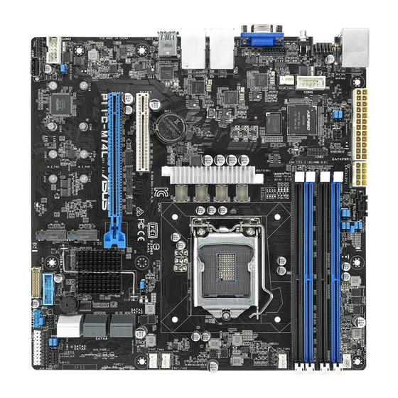
Screw holes Place seven (7) screws into the holes indicated by circles to secure the motherboard to the chassis. DO NOT overtighten the screws! Doing so can damage the motherboard. Place this side towards the rear of the chassis ASUS P11C-M/4L... -
Page 18: Motherboard Layout
2.2.3 Motherboard layout Chapter 2: Hardware Information... -
Page 19: Layout Contents
2-22 VGA controller setting (3-pin VGA_SW1) 2-23 LAN controller setting (3-pin LAN_SW1-4) 2-23 ME firmware force recovery setting (3-pin ME_RCVR1) 2-24 PCH_MFG1 setting (3-pin PCH_MFG1) 2-24 Smart Ride Through (SmaRT) setting (3-pin SMART_PSU1) 2-25 DMLAN setting (3-pin DM_IP_SEL1) 2-25 SATADOM power setting (3-pin DOM1_PWR1) 2-26 CPU PCIE configuration setting (3-pin U2_CFG5-6) 2-26 Rear panel connectors Page RJ-45 port for iKVM 2-27 Q-Code LED 2-27 Power-on Button 2-27 Video Graphics Adapter port 2-27 RJ-45 ports for LAN 1-4 2-27 USB 3.1 Gen 2 ports 1 and 2 2-27 USB 3.1 Gen 1 ports 5 and 6 2-27 ASUS P11C-M/4L... - Page 20 Internal connectors Page Serial ATA 6.0 Gbp/s connectors (7-pin SATA 6Gbps_1-6) 2-29 Hard disk activity LED connector (4-pin HDLED1) 2-29 USB 2.0 connectors (10-1 pin USB1112; 4-pin Type-A USB7) 2-30 USB 3.1 Gen 1 connector (20-1 pin USB3_34) 2-30 F an connectors (4-pin CPU_FAN1, FRNT_FAN1-3, REAR_FAN1) 2-31 Serial General Purpose Input/Output connector (6-1 pin SGPIO1) 2-31 Trusted Platform Module connector (14-1 pin TPM) 2-32 VGA connector (16-pin VGA_HDR1)) 2-32 Serial port connectors (10-1 pin COM1-2) 2-33 Power Supply SMBus connector (5-pin PSUSMB1) 2-33 ATX power connectors (24-pin EATXPWR1, 8-pin EATX12V1) 2-34 System panel connector (20-1 pin PANEL1) 2-35 Auxiliary panel connectors (20-2 pin AUX_PANEL1; 20-pin AUX_ 2-36 PANEL2) Chassis intrusion connector (2-pin INTRUSION1) 2-37 System Management Bus (SMBUS) connector 2-37 (5-1 pin SMBUS1) M.2 (NGFF) connectors (NGFF1-2) 2-38 Thermal sensor cable connector (3-pin TR1) 2-38 Chapter 2: Hardware Information...
-
Page 21: Central Processing Unit (Cpu)
Central Processing Unit (CPU) ® ® The motherboard comes with a surface mount LGA1151 socket designed for the Intel Xeon ® ® ® E-21xx, Intel Core™ i3, Intel Pentium™, and Intel Celeron™ processors. • Upon purchase of the motherboard, ensure that the PnP cap is on the socket and the socket contacts are not bent. Contact your retailer immediately if the PnP cap is missing, or if you see any damage to the PnP cap/socket contacts/motherboard components. ASUS will shoulder the cost of repair only if the damage is shipment/ transit-related. • The product warranty does not cover damage to the socket contacts resulting from incorrect CPU installation/removal, or misplacement/loss/incorrect removal of the PnP cap. 2.3.1 Installing the CPU To install the CPU: Locate the CPU socket on the motherboard. Before installing the CPU, ensure that the socket box is facing toward you and the load lever is on your right. ASUS P11C-M/4L... - Page 22 Press the load lever with your thumb (A), then move it to the right (B) until it is Load lever released from the retention tab. Do not remove the PnP cap yet from the CPU socket. Doing so may bend the pins of the socket. Retention tab Lift the load lever until the load plate is completely lifted.
- Page 23 Some heatsinks come with pre- applied Thermal Interface Material. If so, skip this step. The Thermal Interface Material is toxic and inedible. DO NOT eat it. If it gets into your eyes or touches your skin, wash it off immediately and seek professional medical help. ASUS P11C-M/4L...
-
Page 24: Installing The Cpu Heatsink
2.3.2 Installing the CPU heatsink The Intel LGA1151 processor requires a specially designed CPU heatsink to ensure ® optimum thermal condition and performance. ® • When you buy a boxed Intel processor, a specially designed CPU heatsink or a CPU heatsink with a CPU fan assembly is included depending on the package. If you ® buy a CPU separately, ensure that you use only Intel certified multi-directional CPU heatsink or CPU heatsink with CPU fan. • Use an LGA1151-compatible CPU heatsink and CPU fan assembly only. The LGA1151 socket is incompatible with the LGA775 and LGA1366 sockets in size and dimension. If you purchased a separate CPU heatsink and fan assembly, ensure that the Thermal Interface Material is properly applied to the CPU heatsink or CPU before you install the heatsink and fan assembly. Ensure that you have installed the motherboard to the chassis before you install the CPU fan and heatsink assembly. To install the CPU heatsink and fan: Place the heatsink on top of the installed CPU, making sure that the four fasteners match the holes on the motherboard. -
Page 25: Uninstalling The Cpu Heatsink And Fan
2.3.3 Uninstalling the CPU heatsink and fan To uninstall the CPU heatsink and fan: 1. Disconnect the CPU fan cable from the connector on the motherboard. Rotate each fastener counterclockwise. Pull up two fasteners at a time in a diagonal sequence to disengage the heatsink and fan assembly from the motherboard. Carefully remove the heatsink and fan assembly from the motherboard. 2-11 ASUS P11C-M/4L... -
Page 26: Installing The Cpu Heatsink In Rack
2.3.4 Installing the CPU heatsink in rack The Intel LGA1151 processor requires a specially designed heatsink to ensure optimum ® thermal condition and performance. • Ensure that you use qualified heatsink assembly only. • Ensure that you have applied the thermal interface material to the top of the CPU before installing the heatsink and fan. Peel off the sticker on the heatsink metal plate and affix the plate to the back of the motherboard, matching the standoffs to the heatsink screw holes. Use a Phillips screwdriver to tighten the four heatsink screws using the recommended sequence below. -
Page 27: System Memory
You may install unbuffered DDR4 DIMMs into the DIMM sockets using the memory configurations in this section. UDIMM DIMM Slot Per DIMM Populated DIMM Type Speed Rank per DIMM Channel per Channel Unbuffered DDR4 2666 Single Rank, Dual Rank Unbuffered DDR4 2666 Single Rank, Dual Rank • Always install DIMMs with the same CAS latency. For optimum compatibility, it is recommended that you obtain memory modules from the same vendor. • Start installing the DIMMs in slots A2 and B2 (Blue). 2-13 ASUS P11C-M/4L... -
Page 28: Installing A Dimm On A Single Clip Dimm Socket
2.4.3 Installing a DIMM on a single clip DIMM socket Unlock a DIMM socket by pressing the DIMM notch retaining clip outward. Align a DIMM on the socket such that the notch on the DIMM matches the DIMM slot key on the socket. DIMM slot key Unlocked retaining clip A DIMM is keyed with a notch so that it fits in only one direction. DO NOT force a DIMM into a socket in the wrong direction to avoid damaging the DIMM. Hold the DIMM by both of its ends then insert the DIMM vertically into the socket. Apply force to both ends of the... -
Page 29: Expansion Slots
Secure the card to the chassis with the screw you removed earlier. Replace the system cover. 2.5.2 Configuring an expansion card After installing the expansion card, configure it by adjusting the software settings. Turn on the system and change the necessary BIOS settings, if any. See Chapter 4 for information on BIOS setup. Assign an IRQ to the card. Refer to the tables on the next page. Install the software drivers for the expansion card. When using PCI cards on shared slots, ensure that the drivers support “Share IRQ” or that the cards do not need IRQ assignments. Otherwise, conflicts will arise between the two PCI groups, making the system unstable and the card inoperable. 2-15 ASUS P11C-M/4L... -
Page 30: Interrupt Assignments
2.5.3 Interrupt assignments Standard Interrupt assignments Priority Standard function System Timer Keyboard Controller Programmable Interrupt Communications Port (COM1) Print Port (LPT1) System CMOS/Real Time Clock ACPI Mode when used IRQ Holder for PCI Steering IRQ Holder for PCI Steering PS/2 Compatible Mouse Port Numeric Data Processor * These IRQs are usually available for ISA or PCI devices. 2-16 Chapter 2: Hardware Information... -
Page 31: Pci Express X8 Slot (X8 Link)
PCI Express x8 slot (x8 link) The onboard PCIE 7 provide one x8 Gen3 link to the PCH. These slots support various server class high performance add-on cards. 2.5.5 PCI Express x16 slot (x16 link) The onboard PCIE 6 provides one x16 Gen3 link to CPU. This slot supports VGA cards and various server class high performance add-on cards. No.(Slot location) Short Description 1 x PCI-E x8 (x8 Gen3 Link) 1 (slot 7) PCIE7 2 (slot 6) PCIE6 1 x PCI-E x16 (x16 Gen3 link) PCIe slot 6 shares bandwidth with PCIe slot 7, when PCIe slot 7 is occupied PCIe slot 6 will run in x8 mode. 2-17 ASUS P11C-M/4L... -
Page 32: Installing The Baseboard Management Card
2.5.6 Installing the Baseboard Management Card Follow the steps below to install an optional ASMB9 Management Card on your motherboard. Locate the Baseboard Management Card header on the motherboard. Orient and press the Management Card in place. The motherboard illustration is for reference only. The motherboard layout and appearance may vary depending on the model, but the installation steps remain the same. 2-18 Chapter 2: Hardware Information... -
Page 33: Onboard Leds
The illustration below shows the location of the onboard LED. CATT ERR LED (CATTERR1) The CATT ERR LED indicates that the system has experienced a fatal or catastrophic error and cannot continue to operate. 2-19 ASUS P11C-M/4L... - Page 34 ME LED (MELED1) The ME LED is an onboard LED that blinks when the the ME is operating properly. BMC LED (BMCLED1) The BMC LED blinks to indicate that the on-board BMC is functional. 2-20 Chapter 2: Hardware Information...
- Page 35 Message LED (MLED1) This onboard LED lights up to indicate that there is a temperature warning or a BMC event log is generated. 2-21 ASUS P11C-M/4L...
-
Page 36: Jumpers
Jumpers Clear RTC RAM (3-pin CLRTC1) This jumper allows you to clear the CMOS memory system setup parameters by erasing the CMOS Real Time Clock (RTC) RAM data. The onboard button cell battery powers the RAM data in CMOS, which include system setup information such as system passwords. To erase the RTC RAM: Turn OFF the computer and unplug the power cord. Move the jumper cap from pins 1–2 (default) to pins 2–3. Keep the cap on pins 2–3 for about 5–10 seconds, then move the cap back to pins 1–2. Plug the power cord and turn ON the computer. Hold down the <Del> key during the boot process and enter BIOS setup to reenter data. Except when clearing the RTC RAM, never remove the cap on CLRTC jumper default position. Removing the cap will cause system boot failure! •... -
Page 37: Vga Controller Setting (3-Pin Vga_Sw1)
VGA controller setting (3-pin VGA_SW1) This jumper allows you to enable or disable the onboard VGA controller. Set to pins 1–2 to activate the VGA feature. LAN controller setting (3-pin LAN_SW1-4) ® These jumpers allow you to enable or disable the onboard Intel I210 Gigabit LAN controllers. Set to pins 1-2 to activate the Gigabit LAN feature. 2-23 ASUS P11C-M/4L... -
Page 38: Me Firmware Force Recovery Setting (3-Pin Me_Rcvr1)
ME firmware force recovery setting (3-pin ME_RCVR1) This jumper allows you to force Intel Management Engine (ME) boot from recovery mode when ME become corrupted. PCH_MFG1 setting (3-pin PCH_MFG1) This jumper allows you to update the BIOS ME block. 2-24 Chapter 2: Hardware Information... -
Page 39: Smart Ride Through (Smart) Setting (3-Pin Smart_Psu1)
Smart Ride Through (SmaRT) setting (3-pin SMART_PSU1) This jumper allows you to enable or disable the Smart Ride Through (SmaRT) function. This feature is disabled by default. Set to pins 1-2 to enable it. When enabled, SmaRT allows uninterrupted operation of the system during an AC loss event. DMLAN setting (3-pin DM_IP_SEL1) This jumper allows you to select the DMLAN setting. Set to pins 2-3 to force the DMLAN IP to static mode (IP=10.10.10.10, submask=255.255.255.0). 2-25 ASUS P11C-M/4L... -
Page 40: Satadom Power Setting (3-Pin Dom1_Pwr1)
SATADOM power setting (3-pin DOM1_PWR1) This jumper allows SATA4 to support SATADOM which do not need external power connections. Set to pins 2-3 to activate the SATA4 support feature. CPU PCIE configuration setting (3-pin U2_CFG5-6) These jumpers allow you to configure the speed at which PCIE6 will run at. Refer to the table below for the different jumper configurations. Jumper Setting U2_CFG6 U2_CFG5 PCIE6 slot configuration x16 (Default) x8, x8 x8, x4, x4 This jumper will be disabled when PCIE7 slot is occupied. 2-26 Chapter 2: Hardware Information... -
Page 41: Connectors
Power-on Button: Press this button to turn on the system. Video Graphics Adapter port. This port is for a VGA monitor or other VGA-compatible devices. RJ-45 ports for LAN 1-4. These ports allows Gigabit connection to a Local Area Network (LAN) through a network hub. Refer to the table below for the LAN port LED indications. USB 3.1 Gen 2 ports 1 and 2. These two 4-pin USB ports are available for connecting USB 3.1 Gen 2 devices. USB 3.1 Gen 1 ports 5 and 6. These two 4-pin USB ports are available for connecting USB 3.1 Gen 1 devices. 2-27 ASUS P11C-M/4L... - Page 42 LAN port LED indications ACT/LINK SPEED Activity/Link LED Speed LED Status Description Status Description No link 10 Mbps connection ORANGE Linked ORANGE 100 Mbps connection BLINKING Data activity GREEN 1 Gbps connection ACT/LINK SPEED Dedicated Management LAN port (DM_LAN1) LED indications Activity/Link LED Speed LED ACT/LINK SPEED Status Description...
-
Page 43: Internal Connectors
2.8.2 Internal connectors Serial ATA 6.0 Gbp/s connectors (7-pin SATA 6Gbps_1-6) ® Supported by the Intel C242 chipset, these connectors are for the Serial ATA signal cables for Serial ATA hard disk drives that allows up to 6Gb/s of data transfer rate. If you installed Serial ATA hard disk drives, you can create a RAID 0, RAID 1, RAID 10, or RAID 5 configuration. The actual data transfer rate depends on the speed of Serial ATA hard disks installed. Hard disk activity LED connector (4-pin HDLED1) This LED connector is for the storage add-on card cable connected to the SATA or SAS add-on card. The read or write activities of any device connected to the SATA or SAS add-on card causes the front panel LED to light up. 2-29 ASUS P11C-M/4L... -
Page 44: Usb 2.0 Connectors (10-1 Pin Usb1112; 4-Pin Type-A Usb7)
USB 2.0 connectors (10-1 pin USB1112; 4-pin Type-A USB7) The 10-1 pin connector allows you to connect a USB 2.0 module for additional USB 2.0 front or rear panel ports. The 4-pin USB (Universal Serial Bus) Type-A port is available for connecting USB 2.0 devices. These USB connectors comply with USB 2.0 specification that supports up to 480 Mbps connection speed. DO NOT connect a 1394 cable to the USB connectors. Doing so will damage the motherboard! USB 3.1 Gen 1 connector (20-1 pin USB3_34) This connector allows you to connect a USB 3.1 Gen 1 module for additional USB 3.1 Gen 1 front or rear panel ports. With an installed USB 3.1 Gen 1 module, you can enjoy all the benefits of USB 3.1 Gen 1 including faster data transfer speeds of up to 5 Gb/s, faster charging time for USB-chargeable devices, optimized power efficiency, and backward compatibility with USB 2.0. The USB 3.1 Gen 1 module is purchased separately. The plugged USB 3.1 Gen 1 device may run on xHCI or EHCI mode depending on the operating system’s setting. 2-30 Chapter 2: Hardware Information... -
Page 45: Fan Connectors (4-Pin Cpu_Fan1, Frnt_Fan1-3, Rear_Fan1)
Fan connectors (4-pin CPU_FAN1, FRNT_FAN1-3, REAR_FAN1) The fan connectors support cooling fans. Connect the fan cables to the fan connectors on the motherboard, ensuring that the black wire of each cable matches the ground pin of the connector. • DO NOT forget to connect the fan cables to the fan connectors. Insufficient air flow inside the system may damage the motherboard components. • These are not jumpers! DO NOT place jumper caps on the fan connectors! • All fans feature the ASUS Smart Fan technology. Serial General Purpose Input/Output connector (6-1 pin SGPIO1) The SGPIO 1 connector is used for the Intel Rapid Storage Technology Enterprise SGPIO interface that controls the LED pattern generation, device information, and general purpose data. 2-31 ASUS P11C-M/4L... -
Page 46: Trusted Platform Module Connector (14-1 Pin Tpm)
Trusted Platform Module connector (14-1 pin TPM1) This connector supports a Trusted Platform Module (TPM) system, which can securely store keys, digital certificates, passwords, and data. A TPM system also helps enhance network security, protects digital identities, and ensures platform integrity. VGA connector (16-pin VGA_HDR1) This connector supports the VGA High Dynamic-Range interface. 2-32 Chapter 2: Hardware Information... -
Page 47: Serial Port Connectors (10-1 Pin Com1-2)
Serial port connectors (10-1 pin COM1-2) These connectors are for the serial (COM) ports. Connect the serial port module cable to the connector, then install the module to a slot opening at the back of the system chassis. Power Supply SMBus connector (5-pin PSUSMB1) This connector allows you to connect SMBus (System Management Bus) to the PSU (power supply unit) to read PSU information. Devices communicate with an SMBus host and/or other SMBus devices using the SMBus interface. This connector functions only when you enable the ASUS ASMB9. Power supply is required to meet PMBus specification and customized BMC FW may be needed. Please contact ASUS if your need further support. 2-33 ASUS P11C-M/4L... -
Page 48: Atx Power Connectors (24-Pin Eatxpwr1, 8-Pin Eatx12V1)
ATX power connectors (24-pin EATXPWR1, 8-pin EATX12V1) These connectors are for the ATX power supply plugs. The power supply plugs are designed to fit these connectors in only one orientation. Find the proper orientation and push down firmly until the connectors completely fit. • DO NOT forget to connect the 24-pin and the 8-pin power plugs; otherwise, the system will not boot up. • Use of a power supply unit (PSU) with a higher power output is recommended when configuring a system with more power-consuming devices. The system may become unstable or may not boot up if the power is inadequate. • This motherboard supports ATX2.0 PSU or later version. • Ensure that your PSU can provide at least the minimum power required by your system. 2-34 Chapter 2: Hardware Information... -
Page 49: System Panel Connector (20-1 Pin Panel1)
BIOS settings. Pressing the power switch for more than four (4) seconds while the system is ON turns the system OFF. Reset button (2-pin RESET) This 2-pin connector is for the chassis-mounted reset button for system reboot without turning off the system power. 2-35 ASUS P11C-M/4L... -
Page 50: Auxiliary Panel Connectors
Auxiliary panel connectors (20-2 pin AUX_PANEL1; 20-pin AUX_PANEL2) These connectors are for additional front panel features including front panel SMB, locator LED and switch, chassis intrusion, and LAN LEDs. Front panel SMB (6-1 pin FPSMB) This 6-1 pin connector is for the front panel SMBus cable. LAN activity LED (2-pin LAN1_LED, LAN2_LED) This 2-pin connector is for the Gigabit LAN activity LEDs on the front panel. Locator LED (2-pin LOCATORLED1, 2-pin LOCATORLED2) This 2-pin connector is for the locator LED1 and LED2 on the front panel. Connect the Locator LED cables to these 2-pin connector. The LEDs will light up when the Locator button is pressed. -
Page 51: Chassis Intrusion Connector (2-Pin Intrusion1)
Remove the jumper caps only when you intend to use the chassis intrusion detection feature. System Management Bus (SMBUS) connector (5-1 pin SMBUS1) This connector controls the system and power management-related tasks. This connector processes the messages to and from devices rather than tripping the individual control lines. 2-37 ASUS P11C-M/4L... -
Page 52: Ngff) Connectors (Ngff1-2)
M.2 (NGFF) connectors (NGFF1-2) These connectors allow you to install M.2 devices. These connectors support type 2242 / 2260 / 2280 / 22110 devices on both PCIe x2 and SATA interface. The M.2 (NGFF) device is purchased separately Thermal sensor cable connector (3-pin TR1) This connector allows you to connect a thermal sensor cable that is used for monitoring temperature. Connect the thermal sensor cable to the connector and place its probe to the device that you want to monitor. -
Page 53: Chapter 3: Powering Up
Powering Up This chapter describes the power up sequence, and ways of shutting down the system. Chapter 3: Powering Up... -
Page 54: Starting Up For The First Time
Starting up for the first time After making all the connections, replace the system case cover. Be sure that all switches are off. Connect the power cord to the power connector at the back of the system chassis. Connect the power cord to a power outlet that is equipped with a surge protector. Turn on the devices in the following order: Monitor External storage devices (starting with the last device on the chain) -
Page 55: Powering Off The Computer
While the system is ON, press the power switch for less than four seconds to put the system to sleep mode or to soft-off mode, depending on the BIOS setting. Pressing the power switch for more than four seconds lets the system enter the soft-off mode regardless of the BIOS setting. ASUS P11C-M/4L... -
Page 57: Chapter 4: Bios Setup
BIOS Setup This chapter tells how to change the system settings through the BIOS Setup menus. Detailed descriptions of the BIOS parameters are also provided. -
Page 58: Managing And Updating Your Bios
BIOS in the future. Copy the original motherboard BIOS using the BUPDATER utility. 4.1.1 ASUS CrashFree BIOS 3 utility The ASUS CrashFree BIOS 3 is an auto recovery tool that allows you to restore the BIOS file when it fails or gets corrupted during the updating process. You can update a corrupted BIOS file using a USB flash drive that contains the updated BIOS file. -
Page 59: Asus Ezflash Utility
ASUS EzFlash Utility The ASUS EzFlash Utility feature allows you to update the BIOS using a USB flash disk without having to use a DOS-based utility. Download the latest BIOS from the ASUS website at www.asus.com before using this utility. The succeeding BIOS screens are for reference only. The actual BIOS screen displays may not be the same as shown. -
Page 60: Bupdater Utility
The succeeding BIOS screens are for reference only. The actual BIOS screen displays may not be the same as shown. The BUPDATER utility allows you to update the BIOS file in DOS environment using a bootable USB flash disk drive with the updated BIOS file. Updating the BIOS file To update the BIOS file using the BUPDATER utility: Visit the ASUS website at www.asus.com and download the latest BIOS file for the motherboard. Save the BIOS file to a bootable USB flash disk drive. Download the BUPDATER utility (BUPDATER.exe) from the ASUS support website at www.asus.com/support to the bootable USB flash disk drive you created earlier. Boot the system in DOS mode, then at the prompt, type: BUPDATER /i[filename].CAP where [filename] is the latest or the original BIOS file on the bootable USB flash disk drive, then press <Enter>. A:\>BUPDATER /i[file name]CAP Chapter 4: BIOS Setup... - Page 61 The utility verifies the file, then starts updating the BIOS file. ASUS Tek. EzFlash Utility Current Platform New Platform Platform : P11C-M/4L Platform : P11C-M/4L Version : 0201 Version : 0206 Build date: 04/13/2018 Build date: 04/25/2018 Start Programming Flash. DO NOT SHUTDOWN THE SYSTEM!!! Write DO NOT shut down or reset the system while updating the BIOS to prevent system boot failure! The utility returns to the DOS prompt after the BIOS update process is completed.
-
Page 62: Bios Setup Program
If the system becomes unstable after changing any BIOS settings, load the default settings to ensure system compatibility and stability. Press <F5> and select Yes to load the BIOS default settings. • The BIOS setup screens shown in this section are for reference purposes only, and may not exactly match what you see on your screen. • Visit the ASUS website (www.asus.com) to download the latest BIOS file for this motherboard. Chapter 4: BIOS Setup... -
Page 63: Bios Menu Screen
F or displaying the system temperature, power status, and changing the fan settings Tool For configuring options for special functions Event Logs For changing the event log settings Server Mgmt For changing the server mgmt settings For selecting the save & exit options Save & Exit To select an item on the menu bar, press the right or left arrow key on the keyboard until the desired item is highlighted. ASUS P11C-M/4L... -
Page 64: Menu Items
4.2.3 Menu items The highlighted item on the menu bar displays the specific items for that menu. For example, selecting Main shows the Main menu items. The other items (Advanced, Chipset, Security, Boot,, Monitor, Tool, Event Logs, Server Mgmt, and Save & Exit) on the menu bar have their respective menu items. 4.2.4 Submenu items A solid triangle before each item on any menu screen means that the item has a submenu. To display the submenu, select the item then press <Enter>. 4.2.5 Navigation keys At the bottom right corner of a menu screen are the navigation keys for the BIOS setup program. Use the navigation keys to select items in the menu and change the settings. 4.2.6 General help At the top right corner of the menu screen is a brief description of the selected item. -
Page 65: Main Menu
Navigate to the second page of the screen to see the rest of items in this menu by pressing the Up or Down arrow keys. To quickly go to the last item of the second page, press the Page Down button. Press the Page Up button to go back to the first item in the first page. System Date [Day MM/DD/YYYY] Allows you to set the system date. System Time [HH:MM:SS] Allows you to set the system time. ASUS P11C-M/4L... -
Page 66: Advanced Menu
Advanced menu The Advanced menu items allow you to change the settings for the CPU and other system devices. Take caution when changing the settings of the Advanced menu items. Incorrect field values can cause the system to malfunction. 4-10 Chapter 4: BIOS Setup... -
Page 67: Cpu Configuration
The following items appear only when you set Software Guard Extensions (SGX) to [Enabled] or [Software Controlled]. Select Owner EPOCH input type [No change in Owner EPOCHs] Allows you to select the behavior of EPOCH input type. Configuration options: [No change in Owner EPOCHs] [Change to New Random EPOCHs] [Manual User Defined Owner EPOCHs] SGX Launch Control Policy [Unlocked] Allows you to select the behavior of SGX Launch Control Policy. Configuration options: [Intel Locked] [Unlocked] [Locked] ASUS P11C-M/4L 4-11... - Page 68 The following items appear only when you set SGX Launch Control Policy to [Locked]. SGX LE Public Key Hash 0-3 [0] Allows you to set the Bytes of the Software Guard Extensions (SGX) Launch Enclave Public Key Hash. The following item appears only when you set Software Guard Extensions (SGX) to [Enabled].
-
Page 69: Power & Performance
Intel(R) Speed Shift Technology [Disabled] Allows you to enable or disable Intel(R) Speed Shift Technology support. Enabling will expose the CPPC v2 interface to allow for hardware controlled P-states. Configuration options: [Disabled] [Enabled] HDC Control [Enabled] [Disabled] Disable HDC. [Enabled] Can be enable by OS if OS native support available. ASUS P11C-M/4L 4-13... - Page 70 Turbo Mode [Enabled] Allows you to enable or disable processor turbo mode if EMTTM is also enabled. Configuration options: [Disabled] [Enabled] C-States [Enabled] Allows you to enable or disable CPU power management, this allows the CPU to enter C-state when not it is not 100 % utilized. Configuration options: [Disabled] [Enabled] The following items appears only when you set C-States to [Enabled]. Enhanced C-States [Enabled] Allows you to enable or disable C11E.
-
Page 71: Server Me Configuration
4.4.3 Server ME Configuration TPM Device Selection [PTT] Allows you to select the TPM device. Configuration options: [PTT] [dTPM] 4.4.4 Trusted Computing Security Device Support [Enabled] This item allows you to enable or disable Security Device Support. Configuration options: [Disabled] [Enabled] ASUS P11C-M/4L 4-15... -
Page 72: Apm Configuration
4.4.5 APM Configuration Restore AC Power Loss [Last State] When set to [Power Off], the system goes into off state after an AC power loss. When set to [Power On], the system will reboot after an AC power loss. When set to [Last State], the system goes into either off or on state, whatever the system state was before the AC power loss. Configuration options: [Power Off] [Power On] [Last State] Power On By PCIE/PCI [Disabled] [Disabled] Disables the PCI or PCIE devices to generate a wake event. [Enabled] Enables the PCI or PCIE devices to generate a wake event. Power On By RTC [Disabled] [Disabled] Disables RTC to generate a wake event. [Enabled] W hen set to [Enabled], the items RTC Alarm Date (Days) and Hour/Minute/Second will become user-configurable with set values. 4.4.6 Runtime Error Logging Settings Runtime Error Logging System Enabling [Enabled] This item allows you to enable or disable Runtime Error Logging System. -
Page 73: Onboard Lan Configuration
Intel I210 LAN2-4 LAN Enable [Enabled] Allows you to enable or disable the Intel LAN. Configuration options: [Disabled] [Enabled] The following item appears only when you set Intel LAN Enable to [Enabled]. Intel LAN ROM Type [Disabled] Allows you to select the Intel LAN ROM type. Configuration options: [Disabled] [PXE] [iSCSI] ® Due to Intel limitations, both Intel LAN ROM Type options should be the same when [PXE] or [iSCSI] is selected. ASUS P11C-M/4L 4-17... -
Page 74: Serial Port Console Redirection
4.4.8 Serial Port Console Redirection COM1/COM2 Console Redirection [Disabled] Allows you to enable or disable the console redirection feature. Configuration options: [Disabled] [Enabled] The following item appears only when you set Console Redirection to [Enabled]. Console Redirection Settings These items become configurable only when you enable the Console Redirection item. The settings specify how the host computer and the remote computer (which the user is using) will exchange data. - Page 75 Legacy Console Redirection Port [COM1] Allows you to select a COM port to display redirection of Legacy OS and Legacy OPROM Messages. Configuration options: [COM1] [COM2] Resolution [80x24] Allows you to select a the number of rows and columns in supported redirection. Configuration options: [80x24] [80x25] Redirect After POST [Always Enable] Allows you to select the redirection after POST. Configuration options: [Always Enable] [BootLoader] ASUS P11C-M/4L 4-19...
-
Page 76: Intel Txt Information
Serial Port for Out-of-Band Management/Windows Emergency Management Services (EMS) Console Redirection [Disabled] Allows you to enable or disable the console redirection feature. Configuration options: [Disabled] [Enabled] The following item appears only when you set Console Redirection to [Enabled]. Console Redirection Settings Out-of-Band Mgmt Port [COM1] Microsoft Windows Emergency Management Services (EMS) allow for remote management of a Windows Server OS through a serial port. -
Page 77: Pci Subsystem Settings
Allows you to enable or disable 64-bit capable devices to be decoded in above 4G address space. It only works if the system supports 64-bit PCI decoding. Configuration options: [Disabled] [Enabled] SR-IOV Support [Disabled] This allows you to enable or disable Single Root IO Virtualization Support, if your system has SR-IOV capable PCIe Devices. Configuration options: [Disabled] [Enabled] BME DMA Mitigation [Disabled] This allows you to enable or disable re-enabling Bus Master Attribute disabled during Pci enumeration for PCI Bridges after SMM locked. Configuration options: [Disabled] [Enabled] ASUS P11C-M/4L 4-21... -
Page 78: Usb Configuration
4.4.11 USB Configuration Legacy USB Support [Enabled] [Disabled] The USB devices can be used only for the BIOS setup program. It cannot be recognized in boot devices list. [Enabled] Enables the support for USB devices on legacy operating systems (OS). [Auto] Allows the system to detect the presence of USB devices at startup. If detected, the USB controller legacy mode is enabled. If no USB device is detected, the legacy USB support is disabled. XHCI Hand-off [Enabled] Allows you to enable or disable workaround for OS(s) without XHCI hand-off support. Configuration options: [Disabled] [Enabled] USB Mass Storage Driver Support [Enabled] Allows you to enable or disable USB Mass Storage driver support. Configuration options: [Disabled] [Enabled] Port 60/64 Emulation [Enabled] Allows you to enable or disable Port 60/64 Emulation. -
Page 79: Network Stack Configuration
The following items appear only when you set Network Stack to [Enabled]. Ipv4 PXE Support [Disabled] Enables or disables the Ipv4 PXE Boot Support. If disabled, Ipv4 PXE boot option will not be created. Configuration options: [Disabled] [Enabled] Ipv4 HTTP Support [Disabled] Enables or disables the Ipv4 HTTP Boot Support. If disabled, Ipv4 PXE boot option will not be created. Configuration options: [Disabled] [Enabled] Ipv6 PXE Support [Disabled] Enables or disables the Ipv6 PXE Boot Support. If disabled, Ipv6 PXE boot option will not be created. Configuration options: [Disabled] [Enabled] Ipv6 HTTP Support [Disabled] Enables or disables the Ipv6 HTTP Boot Support. If disabled, Ipv6 PXE boot option will not be created. Configuration options: [Disabled] [Enabled] ASUS P11C-M/4L 4-23... -
Page 80: Csm Configuration
IPSEC Certificate [Enabled] Enables or disables support for IPSEC Certificate. Configuration options: [Disabled] [Enabled] PXE boot wait time [0] Set the wait time to press ESC key to abort the PXE boot. Use the <+> or <-> to adjust the value. The values range from 0 to 5. Media detect count [1] Set the number of times presence of media will be checked. Use the <+> or <-> to adjust the value. The values range from 1 to 50. 4.4.13 CSM Configuration CSM Support [Enabled] This option allows you to enable or disable CSM Support. -
Page 81: Nvme Configuration
Configuration options: [UEFI ] [Legacy] 4.4.14 NVMe Configuration You may view the NVMe controller and Drive information if an NVMe device is connected. 4.4.15 WHEA Configuration Whea Support [Enabled] This item allows you to enable or disable the WHEA support. Configuration options: [Disabled] [Enabled] ASUS P11C-M/4L 4-25... -
Page 82: Tls Auth Configuration
4.4.16 Tls Auth Configuration Allows you to configure the Tls Auth. 4.4.17 iSCSI Configuration Allows you to configure the iSCSi parameters. 4-26 Chapter 4: BIOS Setup... -
Page 83: Chipset Menu
ECC Support [Enabled] Allows you to enable or disable the ECC support. Configuration options: [Disabled] [Enabled] Memory Scrambler [Enabled] Allows you to enable or disable Memory Scrambler. Configuration options: [Disabled] [Enabled] Fast Boot [Disabled] Allows you to enable or disable Fast Boot. Configuration options: [Disabled] [Enabled] ASUS P11C-M/4L 4-27... - Page 84 PEG Port Configuration PEG 0:1:0 Max Link Speed [Auto] Allows you to set the Max Link Speed. Configuration options: [Auto] [Gen1] [Gen2] [Gen3] PEG0 Slot Power Limit Value [75] Set the upper limit on power supplied by slot. Use the <+> or <-> to adjust the value. The values range from 0 to 255. PEG0 Slot Power Limit Scale [1.0x] Allows you to select the scale for the Slot Power Limit Value. Configuration options: [1.0x] [0.1x] [0.01x] [0.001x] PEG0 Physical Slot Number [1] Allows you to set the physical slot number attached to this Port. The number has to be globally unique within the chassis. Use the <+> or <-> to adjust the value. The values range from 0 to 8191.
-
Page 85: Pch-Io Configuration
2048MB. Configuration options: [Disabled] [Enabled] The following item is configurable only when you set VT-d to [Enabled]. X2APIC Opt Out [Disabled] Allows you to enable or disable X2APIC Opt Out. Configuration options: [Disabled] [Enabled] 4.5.2 PCH-IO Configuration PCI Express Configuration PCI Express Clock Gating [Enabled] Allows you to enable or disable PCI Express clock gating for each root port. Configuration options: [Disabled] [Enabled] ASUS P11C-M/4L 4-29... - Page 86 DMI Link ASPM Control [Auto] Allows you to enable or disable control of active state power management of DMI link. Configuration options: [Disabled] [L0s] [L1] [L0sL1] [Auto] Port8xh Decode [Disabled] Allows you to enable or PCI express port 8xh decode. Configuration options: [Disabled] [Enabled] The following item appears only when you set Port8xh Decode to [Enabled]. Port8xh Decode Port# [0] Select PCI Express Port8xh Decode Root Port. User to ensure port availability.
-
Page 87: Security Menu
Administrator Password To set an administrator password: 1. Select the Administrator Password item and press <Enter>. 2. From the Create New Password box, key in a password, then press <Enter>. 3. Confirm the password when prompted. To change an administrator password: 1. Select the Administrator Password item and press <Enter>. 2. From the Enter Current Password box, key in the current password, then press <Enter>. 3. From the Create New Password box, key in a new password, then press <Enter>. 4. Confirm the password when prompted. To clear the administrator password, follow the same steps as in changing an administrator password, but press <Enter> when prompted to create/confirm the password. ASUS P11C-M/4L 4-31... - Page 88 User Password To set a user password: 1. Select the User Password item and press <Enter>. 2. From the Create New Password box, key in a password, then press <Enter>. 3. Confirm the password when prompted. To change a user password: 1. Select the User Password item and press <Enter>. 2. From the Enter Current Password box, key in the current password, then press <Enter>. 3. From the Create New Password box, key in a new password, then press <Enter>. 4. Confirm the password when prompted. To clear a user password: 1.
- Page 89 This item only appears when the item Secure Boot Mode is set to [Custom]. The Key Management item allows you to modify Secure Boot variables and set Key Management page. Factory Key Provision [Disabled] Allows you to provision factory default Secure Boot keys when the system is in Setup Mode. Configuration options: [Disabled] [Enabled] Restore Factory keys This item will install all Factory Default keys. Reset to Setup Mode This item appears only when you load the default Secure Boot keys. This item allows you to clear all default Secure Boot keys. Export Secure Boot Variables This item will ask you if you want to save all secure boot variables. Select Yes if you want to save all secure boot variables, otherwise select No. ASUS P11C-M/4L 4-33...
-
Page 90: Boot Menu
Enroll Efi Image This item will allow the image to run in Secure Boot mode. Configuration options: [Set New] [Append] Device Guard Ready Remove ‘UEFI CA’ from DB Remove Microsoft UEFI CA from Secure Boot DB. Restore DB defaults Restore DB variable to factory defaults. Platform Key (PK) Configuration options: [Details] [Export] [Update] [Delete] Key Exchange Keys (KEK) / Authorized Signatures (DB) / Forbidden Signatures... - Page 91 Sata Support [All Sata Devices] [Last Boot HDD Only] Only last booted HDD device will be available in POST. [All Sata Devices] All SATA devices will be available in OS and POST. VGA Support [EFI Driver] [Auto] O nly legacy OpRom with Legacy OS, and logo will NOT be shown during POST. [EFI Driver] Efi driver will still be installed with EFI OS. USB Support [Full Intial] [Disabled] All USB devices will NOT be available until after OS boot. [Partial Initial] U SB Mass Storage and specific USB port/device will NOT be available before OS boot. [Full Initial] All USB devices will be available in OS and POST. PS2 Devices Support [Enabled] If this option is disabled, PS2 devices will be skipped. Configuration options: [Disabled] [Enabled] ASUS P11C-M/4L 4-35...
-
Page 92: Monitor Menu
Network Stack Driver Support [Disabled] If this option is disabled, Network Stack Driver will be skipped. Configuration options: [Disabled] [Enabled] Redirection Support [Disabled] If this option is disabled, Redirection function will be disabled. Configuration options: [Disabled] [Enabled] The following item appears only when you set Quiet Boot to [Disabled]. POST Report [5 sec] Allows you to set the desired POST Report waiting time from 1 to 10 seconds. Configuration options: [1 sec] - [10 sec] [Until Press ESC] Network Device BBS Priorities / CD/DVD ROM Drive BBS Priorities / Hard Drive BBS Priorities / Floppy Drive BBS Priorities... -
Page 93: Tool Menu
Allows you to set the desired POST Report waiting time from 1 to 10 seconds. Use the <+> or <-> to adjust the value. The values range from 10 to 100. Tool menu ASUS EZ Flash Allows you to run ASUS EZ Flash BIOS ROM Utility when you press <Enter>. Refer to the ASUS EZ Flash Utility section for details. 4.10 Event Logs menu The Event Logs menu items allow you to change the event log settings and view the system event logs. -
Page 94: View Smbios Event Log
When Log is Full [Do Nothing] Choose options for reacting to a full Smbios Event Log. Configuration options: [Do Nothing] [Erase Immediately] Smbios Event Log Standard Settings Log System Boot Event [Enabled] This option allows you to enable or disable logging System boot event. Configuration options: [Disabled] [Enabled] MECI [1] This option allows you to set the number of occurrences of a duplicate event that must pass before the multiple-event counter of log entry is updated. -
Page 95: Server Mgmt Menu
Allows you to enable or disable FRB-2 timer (POST timer). Configuration options: [Disabled] [Enabled] FRB-2 Timer timeout [6 minutes] Allows you to select the FRB-2 Timer Expiration value. Configuration options: [3 minutes] [4 minutes] [5 minutes] [6 minutes] FRB-2 Timer Policy [Do Nothing] Allows you to select the how the system should respond in FRB-2 Timer expires. Configuration options: [Do Nothing] [Reset] [Power Down] [Power Cycle] ASUS P11C-M/4L 4-39... -
Page 96: System Event Log
OS Watchdog Timer [Disabled] This item allows you to start a BIOS timer which can only be shut off by Management Software after the OS loads. Configuration options: [Disabled] [Enabled] The following items are configurable only when OS Watchdog Timer is set to [Enabled]. OS Wtd Timer Timeout [10 minutes] Allows you to configure the length for the OS Boot Watchdog Timer. -
Page 97: Bmc Self Test Log
Log EFI Status Codes [Error code] Allows you to select which codes to log. Configuration options: [Disabled] [Both] [Error code] [Progress code] 4.11.2 Bmc self test log Allows you to change the SEL event log configuration. Erase Log [Yes, On every reset] Choose options for erasing Smbios Event Log. Erasing is done prior to any logging activation during reset. Configuration options: [No] [Yes, On every reset] When Log is Full [Clear Log] Allows you to choose options for reactions to a full Smbios Event Log. Configuration options: [Clear Log] [Do not log any more] ASUS P11C-M/4L 4-41... -
Page 98: Bmc Network Configuration
4.11.3 BMC network configuration The sub-items in this configuration allow you to configure the BMC network parameters. Navigate to the second page of the screen to see the rest of items in this menu by pressing the Up or Down arrow keys. To quickly go to the last item of the second page, press the Page Down button. Press the Page Up button to go back to the first item in the first page. IPV4 DM_LAN1 / Shared LAN Configuration Address source [Unspecified] This item allows you to configure LAN channel parameters statistically or dynamically (by BIOS or BMC). Unspecified option will not modify any BMC network parameters during BIOS phase. -
Page 99: View System Event Log
The following items appear only when IPV6 Support is set to [Enabled]. Configuration Address source [Unspecified] This item allows you to configure LAN channel parameters statistically or dynamically (by BIOS or BMC). Unspecified option will not modify any BMC network parameters during BIOS phase. Configuration options: [Unspecified] [Static] [DynamicBmcDhcp] 4.11.4 View System Event Log This item allows you to view the system event log records. 4.11.5 BMC User Settings The sub-items in this configuration allow you to add, delete, or change BMC user settings. ASUS P11C-M/4L 4-43... -
Page 100: Save & Exit Menu
4.12 Save & Exit menu The Exit menu items allow you to save or discard your changes to the BIOS items. Pressing <Esc> does not immediately exit this menu. Select one of the options from this menu or <F10> from the legend bar to exit. Save Changes and Reset Exit System setup after saving the changes. -
Page 101: Chapter 5: Raid Configuration
RAID Configuration This chapter provides instructions for setting up, creating, and configuring RAID sets using the available utilities. -
Page 102: Setting Up Raid
Setting up RAID ® The motherboard supports the Intel Rapid Storage Technology enterprise Option ROM Utility with RAID 0, RAID 1, RAID 10, and RAID 5 support (for Windows OS and Linux). 5.1.1 RAID definitions RAID 0 (Data striping) optimizes two identical hard disk drives to read and write data in parallel, interleaved stacks. -
Page 103: Installing Hard Disk Drives
Go to the Chipset Menu > PCH-IO Configuration > SATA And RSTe Configuratrion, then press <Enter>. Set SATA Mode to [RAID Mode]. Press <F10> to save your changes and exit the BIOS Setup. Refer to Chapter 4 for details on entering and navigating through the BIOS Setup. ASUS P11C-M/4L... -
Page 104: Intel
® Intel Rapid Storage Technology enterprise SATA/SSATA Option ROM Utility The Intel Rapid Storage Technology enterprise SATA/SSATA Option ROM utility allows you ® to create RAID 0, RAID 1, RAID 10 (RAID 1+0), and RAID 5 set from Serial ATA hard disk drives that are connected to the Serial ATA connectors supported by the Southbridge. -
Page 105: Creating A Raid Set
]-Prev/Next [TAB]-(M)aster [SPACE]-(R)ecovery [ENTER]-Done Use the up/down arrow keys to move the selection bar then press <Space> to select a disk. A small triangle before the Port number marks the selected drive. Press <Enter> when you are done. ASUS P11C-M/4L... - Page 106 Use the up/down arrow keys to select the stripe size for the RAID array (for RAID 0, 10 and 5 only) then press <Enter>. The available stripe size values range from 4 KB to 128 KB. The following are typical values: RAID 0: 128KB RAID 10: 64KB...
-
Page 107: Deleting A Raid Set
<N> to return to the DELETE VOLUME menu. DELETE VOLUME VERIFICATION ALL DATA IN THE VOLUME WILL BE LOST! (This does not apply to Recovery volumes) Are you sure you want to delete volume “Volume0”? (Y/N): ASUS P11C-M/4L... -
Page 108: Resetting Disks To Non-Raid
5.2.3 Resetting disks to Non-RAID Take caution before you reset a RAID volume hard disk drive to non-RAID. Resetting a RAID volume hard disk drive deletes all internal RAID structure on the drive. To reset a RAID set: From the utility main menu, select 3. Reset Disks to Non-RAID and press <Enter>. Press the up/down arrow keys to select the drive(s) or disks of the RAID set you want to reset, then press <Space>. -
Page 109: Exiting The Intel ® Rapid Storage Technology Enterprise
Rebuild completes in the operating system. Select the port of destination disk for rebuilding (ESC to exit): Port Drive Model Serial # Size XXXXXXXXXXX XXXXXXXX XXX.GB ]-Previous/Next [ENTER]-Select [ESC]-Exit Select a destination disk with the same size as the original hard disk. ASUS P11C-M/4L... - Page 110 The utility immediately starts rebuilding after the disk is selected. When done, the status of the degraded RAID volume is changed to “Rebuild”. Intel(R) Rapid Storage Technology enterprise - SATA Option ROM - 4.5.0.1012 Copyright(C) 2003-15 Intel Corporation. All Rights Reserved. MAIN MENU 1.
-
Page 111: Setting The Boot Array In The Bios Setup Utility
Use up/down arrow keys to select the boot priority and press <Enter>. See the Boot menu section of Chapter 4 for more details. From the Exit menu, select Save Changes & Exit, then press <Enter>. When the confirmation window appears, select Yes, then press <Enter>. ASUS P11C-M/4L 5-11... -
Page 112: Intel ® Rapid Storage Technology Enterprise (Windows)
® Intel Rapid Storage Technology enterprise (Windows) The Intel Rapid Storage Technology enterprise allows you to create RAID 0, RAID 1, RAID ® 10 (RAID 1+0), and RAID 5 set(s) from Serial ATA hard disk drives that are connected to the Serial ATA connectors supported by the Southbridge. -
Page 113: Creating A Raid Set
Select Volume Size tab, you can drag the bar to decide the volume size. Click Next. • If you do not want to keep the data on one of the selected disks, select NO when prompted. • If you want to Enable volume write-back cache or Initialize volume, click Advanced. ASUS P11C-M/4L 5-13... - Page 114 Confirm the volume creation, than click Create Volume to continue. This process could take a while depending on the number and size of the disks. You can continue using other applications during this time. Wait until the process is completed, then click OK when prompted. You still need to partition your new volume using Windows Disk Management before adding any data.
-
Page 115: Changing A Volume Type
OK. The available stripe size values range from 4 KB to 128 KB. The following are typical values: RAID 0: 128KB RAID 10: 64KB RAID 5: 64KB We recommend a lower stripe size for server systems, and a higher stripe size for multimedia computer systems used mainly for audio and video editing. ASUS P11C-M/4L 5-15... -
Page 116: Deleting A Volume
5.3.3 Deleting a volume Be cautious when deleting a volume. You will lose all data on the hard disk drives. Before you proceed, ensure that you back up all your important data from your hard drives. To delete a volume: From the utility main menu, select the volume (exp. -
Page 117: Preferences
Allow you to set to show the notification area icon and show system information, warning, or errors here. E-Mail Preferences Allow you to set to sent e-mail of the following events: • Storage system information • Storage system warnings • Storage system errors ASUS P11C-M/4L 5-17... - Page 118 5-18 Chapter 5: RAID Configuration...
-
Page 119: Chapter 6: Driver Installation
Driver Installation This chapter provides the instructions for installing the necessary drivers for different system components in both ® ® Linux and Windows Operating Systems. -
Page 120: Raid Driver Installation
RAID driver installation After creating the RAID sets for your server system, you are now ready to install an operating system to the independent hard disk drive or bootable array. This part provides the instructions on how to install the RAID controller drivers during OS installation. 6.1.1 Creating a USB flash drive with RAID drive ®... - Page 121 Click Browse to continue. Locate the driver in the corresponding folder of the Support DVD or USB flash drive and then click OK to continue. Select the RAID controller driver you need from the list and click Next. ASUS P11C-M/4L...
- Page 122 When the system finishes loading the RAID driver, Replace the motherboard Support DVD with the Windows Server installation disc. • Remove the USB flash drive. • Select the drive to install Windows and click Next. Setup then proceeds with the OS installation. Follow the onscreen instructions to continue.
-
Page 123: Management Applications And Utilities Installation
• The contents of the support DVD are subject to change at any time without notice. Visit the ASUS website (www.asus.com) for the latest updates on software and utilities. ® ®... -
Page 124: Installing The System Drivers
Installing the system drivers This section provides the instructions on how to install the system drivers. You will need to ® manually install the system drivers on a Windows operating system. To install the system drivers: Restart the computer, and then log on with Administrator privileges. Insert the support DVD into the optical drive. - Page 125 Follow the onscreen instructions to complete the installation. ASUS P11C-M/4L...
- Page 126 Chapter 6: Driver Installation...
-
Page 127: Appendix
Appendix This appendix includes additional information that you may refer to when configuring the motherboard. -
Page 128: P11C-M/4L Block Diagram
P11C-M/4L block diagram Appendix... -
Page 129: Q-Code Table
0xD1 Progress CPU PM CSR programming 0xD2 Progress CPU PM MSR programming 0xD3 Progress CPU PM PSTATE transition 0xD4 Progress CPU PM driver exit 0xD5 Progress CPU PM On ready to boot event (continued on the next page) ASUS P11C-M/4L... - Page 130 Action PHASE POST CODE TYPE DESCRIPTION 0x90 Progress BDS started 0x91 Progress Connect device event 0x92 Progress PCI Bus Enumeration 0x93 Progress PCI Bus Enumeration 0x94 Progress PCI Bus Enumeration 0x95 Progress PCI Bus Enumeration 0x96 Progress PCI Bus Enumeration 0x97 Progress Console outout connect event...
-
Page 131: Notices
économique Canada applicables aux appareils radio exempts de licence. L’exploitation est autorisée aux deux conditions suivantes : (1) l’appareil ne doit pas produire de brouillage, et (2) l’utilisateur de l’appareil doit accepter tout brouillage radioélectrique subi, même si le brouillage est susceptible d’en compromettre le fonctionnement. CAN ICES-3(B)/NMB-3(B) ASUS P11C-M/4L... -
Page 132: Reach
If you require assistance please call ASUS Customer Service 1300 2787 88 or visit us at https://www.asus.com/support... -
Page 133: Simplified Eu Declaration Of Conformity
доступний на: www.asus.com/support Cijeli tekst EU izjave o sukladnosti dostupan je na: www.asus.com/support Türkçe AsusTek Computer Inc., bu aygıtın temel gereksinimlerle ve Čeština Společnost ASUSTeK Computer Inc. tímto prohlašuje, že toto ilişkili Yönergelerin diğer ilgili koşullarıyla uyumlu olduğunu beyan... -
Page 134: Asus Contact Information
ASUS contact information ASUSTeK COMPUTER INC. Address 4F, No. 150, Li-Te Rd., Peitou, Taipei 112, Taiwan Telephone +886-2-2894-3447 +886-2-2890-7798 Web site https://www.asus.com Technical Support Telephone +86-21-38429911 +86-21-58668722 ext: 9101 Online Support https://www.asus.com/support/Product/ContactUs/Services/ questionform/?lang=en ASUSTeK COMPUTER INC. (Taiwan) Address 4F, No. 150, Li-Te Rd., Peitou, Taipei 112, Taiwan... - Page 135 +1-510-608-4555 Web site https://www.asus.com/us/ Technical Support Support fax +1-812-284-0883 General support +1-812-282-2787 Online support https://www.asus.com/support/Product/ContactUs/Services/ questionform/?lang=en-us ASUS COMPUTER GmbH (Germany and Austria) Address Harkort Str. 21-23, 40880 Ratingen, Germany +49-2102-959911 Web site https://www.asus.com/de/ Technical Support Telephone +49-1805-010923 Support Fax +49-2102-959911 Online support https://www.asus.com/support/Product/ContactUs/Services/...
- Page 136 Web site https://www.asus.com/nl/ Technical Support Telephone +31-(0)591-5-70292 +31-(0)591-666853 E-mail advance.rma.eu@asus.com Online Support https://www.asus.com/support/Product/ContactUs/Services/ questionform/?lang=nl-nl ASUS Polska Sp. z o.o. (Poland) Address Ul. Postępu 6, 02-676 Warszawa, Poland Web site https://www.asus.com/pl/ Technical Support Telephone +48-225718033 Online Support https://www.asus.com/support/Product/ContactUs/Services/ questionform/?lang=pl-pl ASK-Service (Russia and CIS) г.Москва, ул.
- Page 137 FCC COMPLIANCE INFORMATION Per FCC Part 2 Section 2.1077(a) Asus Computer International Responsible Party: Address: 48720 Kato Rd, Fremont, CA 94538 Phone/Fax No: (510)739-3777/(510)608-4555 hereby declares that the product Product Name : Motherboard Model Number : P11C-M/4L compliance statement: This device complies with part 15 of the FCC Rules. Operation is subject to the...
- Page 138 A-12 Appendix...