Table of Contents
Advertisement
Advertisement
Table of Contents

Related Manuals for Asus P10S WS


Summary of Contents for Asus P10S WS
- Page 1 P10S WS...
- Page 2 Product warranty or service will not be extended if: (1) the product is repaired, modified or altered, unless such repair, modification of alteration is authorized in writing by ASUS; or (2) the serial number of the product is defaced or missing.
-
Page 3: Table Of Contents
Contents Safety information ..................... vii About this guide ....................... viii P10S WS specifications summary ................x Package contents ..................... xiii Installation tools and components ................. xiv Chapter 1: Product Introduction Special features..................1-1 1.1.1 Product highlights................ 1-1 1.1.2 ASUS-exclusive workstation features ......... 1-2 1.1.3... - Page 4 3.6.10 HDD/SSD SMART Information ..........3-37 Monitor menu ................... 3-38 Boot menu ....................3-42 Tool menu ....................3-47 3.9.1 ASUS EZ Flash 3 Utility ............3-47 3.9.2 ASUS Overclocking Profile ............3-48 3.9.3 ASUS SPD Information ............. 3-49 3.10 Exit menu ....................3-50 3.11...
- Page 5 Contents Chapter 4: Software Support Installing an operating system ..............4-1 4.1.1 Windows 7 and USB 3.0 driver for 100 Series ......4-1 ® Support DVD information ................4-8 4.2.1 Running the support DVD ............4-8 4.2.2 Obtaining the software manuals..........4-9 Software information ................
- Page 6 Before you begin ................. 6-1 6.1.3 Installing two CrossFireX™ graphics cards ........ 6-2 6.1.4 Installing the device drivers ............6-4 6.1.5 Enabling the AMD CrossFireX™ technology ......6-4 ® Appendix P10S WS block diagram ..................A-1 Notices ........................A-2 ASUS contact information ..................A-6...
-
Page 7: Safety Information
Safety information Electrical safety • To prevent electrical shock hazard, disconnect the power cable from the electrical outlet before relocating the system. • When adding or removing devices to or from the system, ensure that the power cables for the devices are unplugged before the signal cables are connected. If possible, disconnect all power cables from the existing system before you add a device. -
Page 8: About This Guide
Refer to the following sources for additional information and for product and software updates. ASUS website The ASUS website (www.asus.com) provides updated information on ASUS hardware and software products. Optional documentation Your product package may include optional documentation, such as warranty flyers, that may have been added by your dealer. -
Page 9: Conventions Used In This Guide
Conventions used in this guide To ensure that you perform certain tasks properly, take note of the following symbols used throughout this manual. DANGER/WARNING: Information to prevent injury to yourself when trying to complete a task. CAUTION: Information to prevent damage to the components when trying to complete a task. -
Page 10: P10S Ws Specifications Summary
4 x DIMM, Max 64GB, DDR4 2133 MHz, ECC/ non-ECC UDIMM Dual channel architecture Memory * Refer to www.asus.com for the Memory QVL(Qualified Vendors List). PCIEX16_1: PCI-E x16 slot, x16/ x8 Gen3 Link PCIEX16_2: PCI-E x16 slot, x8 Gen3 Link, switched from PCIEX16_1... - Page 11 - Supports jack-detection, multi-streaming, front panel jack- retasking (MIC) - Optical S/PDIF out port at back I/O ASUS Exclusive ASUS DIGI + Power Control: 3+2+1 Phase Power Design Features - CPU Power: Digital 3-phase power design - iGPU Power: Digital 2-phase power design...
- Page 12 - 1 x COM port header 16 MB Flash ROM, EFI AMI BIOS, PnP, DMI3.0, WfM2.0, SM BIOS BIOS features 3.0, ACPI 5.0a, ASUS EZ Flash Utility, ASUS CrashFree BIOS 3 WfM 2.0, DMI 3.0, WOL by PME, WOR by PME, PXE Manageability...
-
Page 13: Package Contents
Package contents Check your motherboard package for the following items: ASUS P10S WS motherboard User manual Support DVD 8 x Serial ATA 6.0 Gb/s cables 1 x COM port bracket 1 x Q-connector 1 x ASUS Q-Shield 2 x M.2 Screw package... -
Page 14: Installation Tools And Components
Installation tools and components Intel LGA1151 CPU ® Intel LGA1151 compatible CPU Fan ® Phillips (cross) screwdriver SATA hard disk drive PC chassis DIMM 1 bag of screws Power supply unit SATA optical disc drive (optional) Graphics card The tools and components in the table above are not included in the motherboard package. -
Page 15: Chapter 1: Product Introduction
This motherboard has the latest USB 3.1 connectivity built in for the very fastest USB data transfers — that’s up to 10 Gb/s, or twice as fast as USB 3.0. The next-generation standard is completely backward-compatible with your existing USB devices, and you’ll be all set for USB 3.1’s breakneck speeds. ASUS P10S WS... -
Page 16: Asus-Exclusive Workstation Features
The motherboard is European Union’s Energy-related Products (ErP) ready, and ErP requires products to meet certain energy efficiency requirement in regards to energy consumptions. This is in line with ASUS vision of creating environment-friendly and energy- efficient products through product design and innovation to reduce carbon footprint of the product and thus mitigate environmental impacts. -
Page 17: Motherboard Overview
Before you install or remove any component, ensure that the ATX power supply is switched off or the power cord is detached from the power supply. Failure to do so may cause severe damage to the motherboard, peripherals, or components. ASUS P10S WS... -
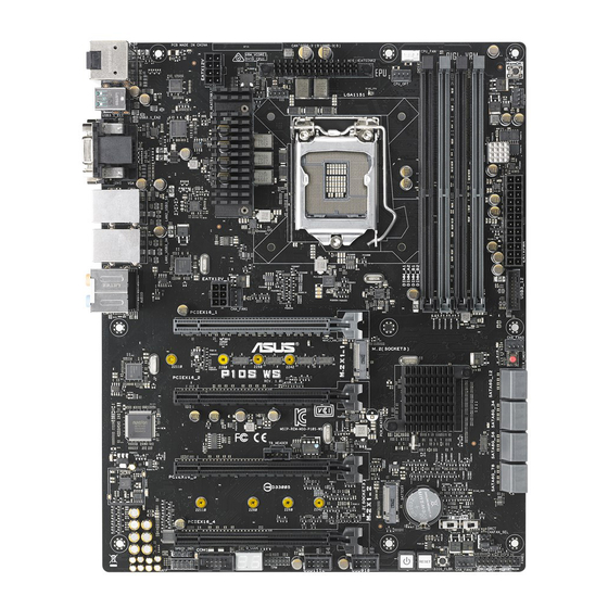
Page 18: Motherboard Layout
1.2.2 Motherboard layout Refer to 1.2.9 Internal connectors and 2.3.1 Rear I/O connection for more information about rear panel connectors and internal connectors. Chapter 1: Product Introduction... -
Page 19: Layout Contents
1-26 19. TPM connector (14-1 pin TPM) 1-25 20. Q-Code LEDs 1-19 21. Serial port connector (10-1 pin COM1) 1-31 22. Front panel audio connector (10-1 pin AAFP) 1-24 23. Digital audio connector (4-1 pin SPDIF_OUT) 1-24 ASUS P10S WS... -
Page 20: Central Processing Unit (Cpu)
Contact your retailer immediately if the PnP cap is missing, or if you see any damage to the PnP cap/socket contacts/motherboard components. ASUS will shoulder the cost of repair only if the damage is shipment/ transit-related. -
Page 21: System Memory
The motherboard comes with four DDR 4 (Double Data Rate 4) Dual Inline Memory Modules (DIMM) slots. A DDR4 module is notched differently from a DDR, DDR2 or DDR3 module. DO NOT install a DDR, DDR2 or DDR3 memory module to the DDR4 slot. Recommended memory configurations ASUS P10S WS... -
Page 22: Memory Configurations
(D/C) from the same vendor. Check with the vendor to get the correct memory modules. • Visit the ASUS website for the latest QVL. Chapter 1: Product Introduction... -
Page 23: Expansion Slots
Unplug the power cord before adding or removing expansion cards. Failure to do so may cause you physical injury and damage motherboard components. Slot No. Slot Description PCIe 3.0/2.0 x16_1 slot PCIe 3.0/2.0 x16_2 slot PCIe 3.0/2.0 x16_3 slot PCIe 3.0/2.0 x16_4 slot ASUS P10S WS... - Page 24 PCI Express 3.0 operating mode Slot Single VGA CrossFireX (single VGA recommended) • We recommend that you provide sufficient power when running CrossFireX™ mode. • Connect a chassis fan to the motherboard connector labeled CHA_FAN1-4 when using multiple graphics cards for better thermal environment. •...
- Page 25 IRQ assignments for this motherboard PCIe x16_1 shared PCIe x16_2 shared PCIe x16_3 shared PCIe x16_4 shared SMBUS Controller shared Intel SATA Controller shared Intel LAN1(I210) shared Intel LAN2(I210) shared Intel xHCI shared HD Audio shared ASMedia 1142_1 shared ASUS P10S WS 1-11...
-
Page 26: Onboard Buttons And Switches
1.2.6 Onboard buttons and switches Onboard buttons and switches allow you to fine-tune performance when working on a bare or open-case system. This is ideal for overclockers and gamers who continually change settings to enhance system performance. Power-on button The motherboard comes with a power-on button that allows you to power up or wake up the system. - Page 27 BIOS default settings. A message will appear during POST reminding you that the BIOS has been restored to its default settings. • We recommend that you download and update to the latest BIOS version from www.asus.com after using the MemOK! function. ASUS P10S WS 1-13...
- Page 28 EPU switch Enable this switch to automatically detect the current PC loadings and intelligently moderate the power consumption. Enable this switch when the system is powered off. • The EPU LED (OLED2) near the EPU switch lights up when the EPU switch is enabled.
- Page 29 Clear CMOS button (CLR_CMOS) Press this button to clear the BIOS setup information only when the systems hangs due to overclocking. ASUS P10S WS 1-15...
-
Page 30: Jumpers
1.2.7 Jumpers Chassis Fan control setting (3-pin CHAFAN_SEL) This jumpers allow you to switch fan pin selection. The CHAFAN_SEL jumper is for the front fans and rear fans control. Set pins 1-2 when using 3-pin fans or pins 2-3 when using 4-pin fans. -
Page 31: Onboard Leds
(Power-On-Self Test): CPU, memory modules, VGA card, and hard disk drives. If an error is found, the critical component’s LED stays lit up until the problem is solved. EPU LED (OLED2) The EPU LED lights up when the EPU switch is enabled. ASUS P10S WS 1-17... - Page 32 USB BIOS Flashback LED (FLBK_LED) The BIOS Flashback LED flashes when you press the BIOS Flashback button for BIOS update. Q-Code LEDs The Q-Code LED design provides you with a 2-digit error code that displays the system status. Refer to the Q-Code table on the next page for details. Chapter 1: Product Introduction 1-18...
- Page 33 S3 Resume is stared (S3 Resume PPI is called by the DXE IPL) S3 Boot Script execution Video repost OS S3 wake vector call Reserved for future AMI progress codes E4 – E7 S3 Resume Failed (continued on the next page) ASUS P10S WS 1-19...
- Page 34 Code Description S3 Resume PPI not Found S3 Resume Boot Script Error S3 OS Wake Error EC – EF Reserved for future AMI error codes Recovery condition triggered by firmware (Auto recovery) Recovery condition triggered by user (Forced recovery) Recovery process started Recovery firmware image is found Recovery firmware image is loaded Reserved for future AMI progress codes...
- Page 35 No Console Output Devices are found No Console Input Devices are found Invalid password Error loading Boot Option (LoadImage returned error) Boot Option is failed (StartImage returned error) Flash update is failed Reset protocol is not available ASUS P10S WS 1-21...
- Page 36 ACPI/ASL Checkpoints (under OS) Code Description System is entering S3 sleep state System is entering S4 sleep state System is entering S5 sleep state System is waking up from the S3 sleep state System is waking up from the S4 sleep state System has transitioned into ACPI mode.
-
Page 37: Internal Connectors
Before creating a RAID set, refer to section 5.1 RAID configurations or the manual bundled in the motherboard support DVD. • These SATA ports are for data drives only. • M.2_1 shares SATA ports with SATA6G_5. • M.2_2 shares SATA ports with SATA6G_6. ASUS P10S WS 1-23... - Page 38 Digital audio connector (4-1 pin SPDIF_OUT) This connector is for an additional Sony/Philips Digital Interface (S/PDIF) port. Connect the S/PDIF Out module cable to this connector, then install the module to a slot opening at the back of the system chassis. The S/PDIF module is purchased separately.
- Page 39 This connector supports a Trusted Platform Module (TPM) system, which securely store keys, digital certificates, passwords and data. A TPM system also helps enhance network security, protect digital identities, and ensures platform integrity. The TPM module is purchased separately. ASUS P10S WS 1-25...
- Page 40 DO NOT connect a 1394 cable to the USB connectors. Doing so will damage the motherboard! You can connect the front panel USB cable to the ASUS Q-Connector (USB) first, and then install the Q-Connector (USB) to the USB connector onboard if your chassis supports front panel USB ports.
- Page 41 USB 3.0 ports under Windows ® • The plugged USB 3.0 device may run on xHCI or EHCI mode depending on the operating system’s setting. • These USB 3.0 ports only support Turbo Mode when using USB 3.0 Boost feature. ASUS P10S WS 1-27...
- Page 42 • The CPU_FAN connector supports the CPU fan of maximum 1A (12 W) fan power. • The CPU_FAN connector and CHA_FAN connectors support the ASUS FAN Xpert 3 feature. • The CPU fan connector detects the type of CPU fan installed and automatically switches the control modes.
- Page 43 • If you want to use two or more high-end PCI Express x16 cards, use a PSU with 1000W power or above to ensure the system stability. ASUS P10S WS 1-29...
-
Page 44: System Panel Connector
System panel connector (20-5 pin PANEL) This connector supports several chassis-mounted functions. • System power LED (3-1 pin or 2-pin PLED) This 3-1 pin or 2-pin connector is for the system power LED. Connect the chassis power LED cable to this connector. The system power LED lights up when you turn on the system power, and blinks when the system is in sleep mode. - Page 45 This connector is for a serial (COM) port. Connect the serial port module cable to this connector, then install the module to a slot opening at the back of the system chassis. The COM module is purchased separately. ASUS P10S WS 1-31...
- Page 46 M.2 socket 3 This socket allows you to install an M.2 (NGFF) SSD module. • This socket supports M Key and type 2242/2260/2280/22110 storage devices. • M.2 X1_1 shares SATA ports with SATA6G_5 and M.2 X1_2 shares SATA ports with SATA6G_6.
-
Page 47: Chapter 2: Basic Installation
2.1.1 Motherboard installation Install the ASUS Q-Shield to the chassis rear I/O panel. Place the motherboard into the chassis, ensuring that its rear I/O ports are aligned to the chassis’ rear I/O panel. - Page 48 Place nine (9) screws into the holes indicated by circles to secure the motherboard to the chassis. DO NOT overtighten the screws! Doing so can damage the motherboard. Chapter 2: Basic Installation...
-
Page 49: Cpu Installation
2.1.2 CPU installation • Ensure that you install the correct CPU designed for LGA1151 socket only. DO NOT install a CPU designed for LGA1155 and LGA1156 sockets on the LGA1151 socket. • Upon purchase of the motherboard, ensure that the PnP cap is on the socket and the socket contacts are not bent. Contact your retailer immediately if the PnP cap is missing, or if you see any damage to the PnP cap/socket contacts/motherboard components. ASUS will shoulder the cost of repair only if the damage is shipment/ transit-related. • The product warranty does not cover damage to the socket contacts resulting from incorrect CPU installation/removal, or misplacement/loss/incorrect removal of the PnP cap. Load lever Retention tab CPU notches Gold triangle A l i g n m e n t... - Page 50 Load lever Load lever Retention tab Retention lock Chapter 2: Basic Installation...
-
Page 51: Cpu Heatsink And Fan Assembly Installation
2.1.3 CPU heatsink and fan assembly installation Apply the Thermal Interface Material to the CPU heatsink and CPU before you install the heatsink and fan, if necessary. To install the CPU heatsink and fan assembly ASUS P10S WS... - Page 52 To uninstall the CPU heatsink and fan assembly Chapter 2: Basic Installation...
-
Page 53: Dimm Installation
2.1.4 DIMM installation To remove a DIMM ASUS P10S WS... -
Page 54: Atx Power Connection
2.1.5 ATX power connection • DO NOT connect the 6-pin power plug only, the motherboard may overheat under heavy usage. • Ensure to connect the 8-pin power plug, or connect both the 8-pin and 6-pin power plugs. Chapter 2: Basic Installation... -
Page 55: Sata Device Connection
2.1.6 SATA device connection ASUS P10S WS... -
Page 56: Front I/O Connector
2.1.7 Front I/O connector To install ASUS Q-Connector To install USB 2.0 connector To install front panel audio connector AAFP USB 2.0 To install USB 3.0 connector USB 3.0 Chapter 2: Basic Installation 2-10... -
Page 57: Expansion Card Installation
2.1.8 Expansion card installation To install PCIe x16 cards ASUS P10S WS 2-11... -
Page 58: Bios Update Utility
BIOS update utility USB BIOS Flashback USB BIOS Flashback allows you to easily update the BIOS without entering the existing BIOS or operating system. Simply insert a USB storage device to the USB port (the USB port hole marked in green on the I/O shield) then press the USB BIOS Flashback button for three seconds to automatically update the BIOS. To use USB BIOS Flashback: Place the bundled support DVD to the optical drive and install the USB BIOS Flashback Wizard. Follow the onscreen instructions to complete the installation. - Page 59 • If the light flashes for five seconds and turns into a solid light, this means that the BIOS Flashback is not operating properly. This may be caused by improper installation of the USB storage device and filename/file format error. If this scenario happens, please restart the system to turn off the light. • Updating BIOS may have risks. If the BIOS program is damaged during the process and results to the system’s failure to boot up, please contact your local ASUS Service Center. ASUS P10S WS 2-13...
-
Page 60: Motherboard Rear And Audio Connections
Motherboard rear and audio connections 2.3.1 Rear I/O connection Rear panel connectors Optical S/PDIF Out port DisplayPort USB 3.1 Type-A port EA2 (supports USB 3.1 Type-C port EC1 (supports USB 3.1 Boost) USB 3.1 Boost) VGA port DVI-D port Intel LAN port 1 and 2 (I210-AT)* USB 3.0 ports 3, 4, 5, and 6 (lower left ® port supports USB BIOS Flashback - red light) HDMI 1.4b port Audio I/O ports** * and **: Refer to the tables on the next page for LAN port LEDs and audio port definitions. Chapter 2: Basic Installation 2-14... - Page 61 Activity Link LED Speed LED Status Description Status Description ACT/LINK SPEED No link 10 Mbps connection Orange Linked Orange 100 Mbps connection Orange (Blinking) Data activity Green 1 Gbps connection Orange (Blinking Ready to wake up LAN port then steady) from S5 mode You can disable the LAN controllers in BIOS. Once disabled, the LAN2 port’s ACT/LINK LED and SPEED LED stop blinking. For LAN1 port, the ACT/LINK LED still blinks even if you disabled it. ASUS P10S WS 2-15...
-
Page 62: Audio I/O Connections
** Audio 2, 4, 6, or 8-channel configuration Port Headset 4-channel 6-channel 8-channel 2-channel Line In Light Blue Line In Line In Line In Lime Line Out Front Speaker Out Front Speaker Out Front Speaker Out Mic In Pink Mic In Mic In Mic In Center/Subwoofer Orange – – Center/Subwoofer Black – Rear Speaker Out Rear Speaker Out Rear Speaker Out... - Page 63 Connect to 2.1 channel Speakers Connect to 4.1 channel Speakers Connect to 5.1 channel Speakers If you are using Windows 8.1 platform, use only the gray audio port for Side Speaker Out in a 6-channel configuration. ASUS P10S WS 2-17...
-
Page 64: Starting Up For The First Time
Connect to 7.1 channel Speakers When the DTS UltraPC II function is enabled, ensure to connect the rear speaker to the gray port. Starting up for the first time After making all the connections, replace the system case cover. Ensure that all switches are off. Connect the power cord to the power connector at the back of the system chassis. Connect the power cord to a power outlet that is equipped with a surge protector. Turn on the devices in the following order: Monitor b. External SCSI devices (starting with the last device on the chain) System power After applying power, the system power LED on the system front panel case lights up. For systems with ATX power supplies, the system LED lights up when you press the ATX power button. If your monitor complies with the “green” standards or if it has a “power standby” feature, the monitor LED may light up or change from orange to green after the system LED turns on. -
Page 65: Turning Off The Computer
Turning off the computer While the system is ON, press the power button for less than four seconds to put the system on sleep mode or soft-off mode, depending on the BIOS setting. Press the power switch for more than four seconds to let the system enter the soft-off mode regardless of the BIOS setting. ASUS P10S WS 2-19... - Page 66 Chapter 2: Basic Installation 2-20...
-
Page 67: Chapter 3: Bios Setup
BIOS Setup Knowing BIOS The new ASUS UEFI BIOS is a Unified Extensible Interface that complies with UEFI architecture, offering a user-friendly interface that goes beyond the traditional keyboard- only BIOS controls to enable a more flexible and convenient mouse input. You can easily navigate the new UEFI BIOS with the same smoothness as your operating system. -
Page 68: Bios Setup Program
BIOS setup program Use the BIOS Setup to update the BIOS or configure its parameters. The BIOS screen include navigation keys and brief onscreen help to guide you in using the BIOS Setup program. Entering BIOS at startup To enter BIOS Setup at startup, press <Delete> during the Power-On Self Test (POST). If you do not press <Delete>, POST continues with its routines. -
Page 69: Ez Mode
Click to go to Advanced mode Loads optimized Search on the FAQ default settings Click to display boot devices Selects the boot device priority The boot device options vary depending on the devices you installed to the system. ASUS P10S WS... -
Page 70: Advanced Mode
3.2.2 Advanced Mode The Advanced Mode provides advanced options for experienced end-users to configure the BIOS settings. The figure below shows an example of the Advanced Mode. Refer to the following sections for the detailed configurations. To switch from EZ Mode to Advanced Mode, click Advanced Mode(F7) or press the <F7> hotkey. -
Page 71: Menu Bar
Q-Fan Control (F6) This button above the menu bar displays the current settings of your fans. Use this button to manually tweak the fans to your desired settings. Refer to section 3.2.3 QFan Control for more information. ASUS P10S WS... -
Page 72: Hot Keys
Move your mouse over this button to show a QR code, scan this QR code on your mobile device to connect to the BIOS FAQ web page of the ASUS support website. You can also scan the following QR code:... -
Page 73: Qfan Control
Click to activate DC Mode configured PWM Mode Select a profile to apply to Click to apply the fan setting your fans Click to undo the Click to go back to main menu changes Select to manually configure your fans ASUS P10S WS... - Page 74 Configuring fans manually Select Manual from the list of profiles to manually configure your fans’ operating speed. Speed points Select to manually configure your fans To configure your fans: Select the fan that you want to configure and to view its current status. Click and drag the speed points to adjust the fans’...
-
Page 75: My Favorites
My Favorites is your personal space where you can easily save and access your favorite BIOS items. My Favorites comes with several performance, power saving, and fast boot related items by default. You can personalize this screen by adding or removing items. ASUS P10S WS... - Page 76 Adding items to My Favorites To add BIOS items: Press <F3> on your keyboard or click from the BIOS screen to open Setup Tree Map screen. On the Setup Tree Map screen, select the BIOS items that you want to save in My Favorites screen.
-
Page 77: Main Menu
RTC RAM via the Clear CMOS button. • The Administrator or User Password items on top of the screen show the default [Not Installed]. After you set a password, these items show [Installed]. ASUS P10S WS 3-11... -
Page 78: Administrator Password
Administrator Password If you have set an administrator password, we recommend that you enter the administrator password for accessing the system. Otherwise, you might be able to see or change only selected fields in the BIOS setup program. To set an administrator password: Select the Administrator Password item and press <Enter>. -
Page 79: Ai Tweaker Menu
Select any of these preset overclocking configuration options: [Auto] Loads the optimal settings for the system. [Manual] Automatically optimizes the CPU ratio and BCLK frequency. The following item appears only when you set the Ai Overclocking Tuner to [Manual]. ASUS P10S WS 3-13... - Page 80 [+0.17] ASUS MultiCore Enhancement [Auto] [Auto] This item allows you to maximize the oveclocking performance optimized by ASUS core ratio settings. [Disabled] This item allows you to set to default core ratio settings. CPU Core Ratio [Auto] This item allows you to set the CPU core ratio limit per core or synchronize automatically to all cores.
-
Page 81: Dram Timing Control
This item allows you to enable or disable the odd ratio mode for better granularity. Configuration options: [Disabled] [Enabled] EPU Power Saving Mode [Disabled] The ASUS EPU (Energy Processing Unit) sets the CPU in its minimum power consumption settings. Configuration options: [Disabled] [Enabled] CPU SVID Support Disable this item to stop the CPU from communicating with the external voltage regulator. - Page 82 Secondary Timings DRAM RAS# to RAS# Delay L [Auto] Configuration options: [Auto] [1] – [15] DRAM RAS# to RAS# Delay S [Auto] Configuration options: [Auto] [1] – [15] DRAM REF Cycle Time [Auto] Configuration options: [Auto] [1] – [1023] DRAM Refresh Interval [Auto] Configuration options: [Auto] [1] –...
- Page 83 Configuration options: [Auto] [0] - [15] CMD Falling Slope Offset [Auto] Configuration options: [Auto] [0] - [1] Ctl Falling Slope [Auto] Configuration options: [Auto] [0] - [15] Ctl Falling Slope Offset [Auto] Configuration options: [Auto] [0] - [1] ASUS P10S WS 3-17...
- Page 84 Clk Falling Slope [Auto] Configuration options: [Auto] [0] - [15] Clk Falling Slope Offset [Auto] Configuration options: [Auto] [0] - [1] RTL IOL control DRAM RTL INIT Value [Auto] Configuration options: [Auto] [0] - [127] DRAM RTL (CHA DIMM0 Rank0) [Auto] Configuration options: [Auto] [0] - [127] DRAM RTL (CHA DIMM0 Rank1) [Auto] Configuration options: [Auto] [0] - [127]...
- Page 85 Configuration options: [Auto] [0] - [63] tRDRD_dd [Auto] Configuration options: [Auto] [0] - [63] tRDWR_dr [Auto] Configuration options: [Auto] [0] - [63] tRDWR_dd [Auto] Configuration options: [Auto] [0] - [63] tWRWR_dr [Auto] Configuration options: [Auto] [0] - [63] ASUS P10S WS 3-19...
- Page 86 tWRWR_dd [Auto] Configuration options: [Auto] [0] - [63] tWRRD_dr [Auto] Configuration options: [Auto] [0] - [63] tWRRD_dd[Auto] Configuration options: [Auto] [0] - [63] TWRPRE [Auto] Configuration options: [Auto] [0] - [127] TRDPRE [Auto] Configuration options: [Auto] [0] - [15] tREFIX9 [Auto] Configuration options: [Auto] [0] - [127] OREF_RI[Auto] Configuration options: [Auto] [0] –...
- Page 87 Configuration options: [Auto] [0.01] - [62.49] IA DC Load Line [Auto] This item allows you to set the DC loadline defined in 1/100 mOhms. Use the <+> and <-> keys to adjust the value. Configuration options: [Auto] [0.01] - [62.49] ASUS P10S WS 3-21...
- Page 88 CPU Core/Cache Current Limit Max. [Auto] This item allows you to configure a higher current limit to prevent a frequency or power throttling when overclocking. Use the <+> and <-> keys to adjust the value. Configuration options: [Auto] [0.00] - [255.50] CPU Graphics Current Limit Max.
-
Page 89: Advanced Menu
The Advanced menu items allow you to change the settings for the CPU and other system devices. Be cautious when changing the settings of the Advanced menu items. Incorrect field values can cause the system to malfunction. ASUS P10S WS 3-23... -
Page 90: Cpu Configuration
3.6.1 CPU Configuration The items in this menu show the CPU-related information that the BIOS automatically detects. The items in this menu may vary based on the CPU installed. Hyper-threading [Enabled] This item allows a hyper-threading processor to appear as two logical processors, allowing the operating system to schedule two threads or processors simultaneously. - Page 91 When enabled, CPU will switch to minimum speed when all cores enter C-State. Configuration options: [Enabled] [Disabled] CPU C3 Report [Enabled] This item allows you to disable or enable the CPU C3 report to the operating system. Configuration options: [Enabled] [Disabled] ASUS P10S WS 3-25...
-
Page 92: Platform Misc Configuration
CPU C6 Report [Enabled] This item allows you to disable or enable the CPU C6 report to the operating system. Configuration options: [Enabled] [Disabled] CPU C7 Report [CPU C7s] This item allows you to disable or enable the CPU C7 report to the operating system. - Page 93 ASPM to take effect. Configuration options: [Disabled] [L1] PEG ASPM [Disabled] This item allows you to select the ASPM state for energy-saving conditions, or use the ASUS optimized energy saving profile. Configuration options: [Disabled] [Auto] [ASPM L0s] [ASPM L1] [ASPM L0sL1]...
-
Page 94: System Agent (Sa) Configuration
3.6.3 System Agent (SA) Configuration VT-d [Disabled] Allows you to enable virtualization technology function on memory control hub. Configuration options: [Enabled] [Disabled] Graphics Configuration This item allows you to select a primary display from CPU and PCIe graphical devices. iGPU Multi-Monitor [Disabled] Set this item to [Enabled] to empower both integrated and discrete graphics for multi- monitor output. -
Page 95: Pch Configuration
PCH Configuration PCI Express Configuration This item allows you to configure the PCI Express slots. PCIe Speed [Auto] This item allows your system to automatically select the PCI Express port speed. Configuration options: [Auto] [Gen1] [Gen2] [Gen3] ASUS P10S WS 3-29... -
Page 96: Pch Storage Configuration
Scroll down to display the other BIOS items. M.2 X1_1 Hyper kit Mode [Disabled] Disable this option for M.2 devices. Enable this option for “ASUS Hyper kit” card. Configuration options: [Disabled] [Enabled] M.2 X1_2 Hyper kit Mode [Disabled] Disable this option for M.2 devices. Enable this option for “ASUS Hyper kit” card. - Page 97 This item allows you to enable or disable the selected SATA port. Configuration options: [Disabled] [Enabled] Hot Plug [Disabled] These items appears only when the SATA Mode Selection is set to [AHCI] and allows you to enable or disable SATA Hot Plug Support. Configuration options: [Disabled] [Enabled] ASUS P10S WS 3-31...
-
Page 98: Usb Configuration
3.6.6 USB Configuration The items in this menu allow you to change the USB-related features. The Mass Storage Devices item shows the auto-detected values. If no USB device is detected, the item shows None. Legacy USB Support [Enabled] [Enabled] Your system supports the USB devices in legacy operating systems. [Disabled] Your USB devices can be used for BIOS setup only and cannot be recognized in the boot devices list. -
Page 99: Network Stack Configuration
The following item appears only when you set the Network Stack to [Enabled]. Ipv4/Ipv6 PXE Support [Enabled] This item allows you to enable or disable the Ipv4/Ipv6 PXE wake event. Configuration options: [Disabled] [Enabled] 3.6.8 Onboard Devices Configuration Scroll down to view the other BIOS items. ASUS P10S WS 3-33... - Page 100 HD Audio Controller [Enabled] This item allows you to use the Azalia High Definition Audio Controller Configuration options: [Disabled] [Enabled] The following items appear only when you set the HD Audio Controller to [Enabled]. Front Panel Type [HD Audio] This item allows you to set the front panel audio connector (AAFP) mode to legacy AC’97 or high-definition audio depending on the audio standard that the front panel audio module supports.
- Page 101 This item allows you to enable or disable the Serial Port. Configuration options: [On] [Off] Change Settings [IO=3F8h; IRQ=4] This item allows you to select an optimal setting for Super IO device. Configuration options: [IO=3F8h; IRQ=4] [IO=2F8h; IRQ=3] [IO=3E8h; IRQ=4] [IO=2E8h; IRQ=3] ASUS P10S WS 3-35...
-
Page 102: Apm Configuration
3.6.9 APM Configuration ErP Ready [Disabled] This item allows you to switch off some power at S4+S5 or S5 to get the system ready for ErP requirement. When set to [Enabled], all other PME options are switched off. Configuration options: [Disabled] [Enabled (S4+S5] [Enabled (S5)] Restore AC Power Loss [Power Off] This item allows your system to go to ON state, OFF state, or both states after an AC power loss. -
Page 103: Hdd/Ssd Smart Information
3.6.10 HDD/SSD SMART Information This menu displays the SMART information of the connected devices. ASUS P10S WS 3-37... -
Page 104: Monitor Menu
Monitor menu The Monitor menu displays the system temperature/power status, and allows you to change the fan settings. Scroll down to display the other BIOS items. CPU Temperature / Motherboard Temperature [xxx°C/xxx°F] The onboard hardware monitor automatically detects and displays the CPU, motherboard, VRM, PCH Core, and SENSOR1 temperatures. - Page 105 CPU fan will operate at the maximum duty cycle. CPU Middle Temperature [25] Use the <+> or <-> keys to adjust the middle limit of the CPU temperature. The values range from 20 to 75. ASUS P10S WS 3-39...
- Page 106 CPU Fan Middle. Duty Cycle (%) [20] Use the <+> or <-> keys to adjust the maximum CPU fan duty cycle. The values range from 20% to 100%. When the CPU temperature reaches the middle limit, the CPU fan will operate at the middle duty cycle. CPU Lower Temperature [20] Use the <+>...
- Page 107 Enable this item for Over Voltage Protection (OVP) and Under Voltage Protection (UVP) functions. Configuration options: [On] [Off] Chassis Intrude Detect Support [Off] Enable this item for Chassis Intrude Detect Support function. Configuration options: [On] [Off] ASUS P10S WS 3-41...
-
Page 108: Boot Menu
Boot menu The Boot menu items allow you to change the system boot options. Fast Boot [Enabled] [Disabled] Allows your system to go back to its normal boot speed. [Enabled] Allows your system to accelerate the boot speed. The following items appear only when you set the Fast Boot to [Enabled]. Next Boot after AC Power Loss [Normal Boot] [Normal Boot] Returns to normal boot on the next boot after an AC power loss. - Page 109 Configuration options: [Disabled] [Enabled] Option ROM Messages [Enabled] [Enabled] The Option ROM Messages will be shown during the POST. [Disabled] Only the ASUS logo will be shown during the POST. Interrupt 19 Capture [Disabled] [Enabled] Execute the trap right away. [Disabled] Execute the trap during legacy boot.
-
Page 110: Secure Boot
CSM (Compatibility Support Module) This item allows you to configure the CSM (Compatibility Support Module) items to fully support the various VGA, bootable devices and add-on devices for better compatibility. Launch CSM [Enabled] [Auto] The system automatically detects the bootable devices and the add- on devices. - Page 111 Allows you to load the additional db from a storage device so that more images can be loaded securely. The db file must be formatted as a UEFI variable structure with time-based authenticated variable. DBX Management ASUS P10S WS 3-45...
-
Page 112: Boot Option Priorities
OS in Safe Mode, press <F8> after POST (Windows 8 not supported). • To select the boot device during system startup, press <F8> when the ASUS Logo appears. Boot Override These items displays the available devices. The number of device items that appears on the screen depends on the number of devices installed in the system. -
Page 113: Tool Menu
3.9.1 ASUS EZ Flash 3 Utility This item allows you to run ASUS EZ Flash 3. When you press <Enter>, a confirmation message appears. Use the left/right arrow key to select between [Yes] or [No], then press <Enter> to confirm your choice. -
Page 114: Asus Overclocking Profile
3.9.2 ASUS Overclocking Profile This item allows you to store or load multiple BIOS settings. Load from Profile This item allows you to load the previous BIOS settings saved in the BIOS Flash. Key in the profile number that saved your BIOS settings, press <Enter>, and then select Yes. -
Page 115: Asus Spd Information
3.9.3 ASUS SPD Information This item allows you to view the DRAM SPD information. ASUS P10S WS 3-49... -
Page 116: Exit Menu
3.10 Exit menu The Exit menu items allow you to load the optimal default values for the BIOS items, and save or discard your changes to the BIOS items. You can access the EZ Mode from the Exit menu. Load Optimized Defaults This option allows you to load the default values for each of the parameters on the Setup menus. -
Page 117: Updating Bios
® ASUS EZ Flash 3: Updates the BIOS using a USB flash drive. ASUS CrashFree BIOS 3: Restores the BIOS using the motherboard support DVD or a USB flash drive when the BIOS file fails or gets corrupted. 3.11.1... -
Page 118: Asus Ez Flash 3
3.11.2 ASUS EZ Flash 3 ASUS EZ Flash 3 allows you to download and update to the latest BIOS through the Internet without having to use a bootable floppy disk or an OS-based utility. Updating through the Internet varies per region and Internet conditions. Check your local Internet connection before updating through the Internet. - Page 119 To update the BIOS by Internet: Enter the Advanced Mode of the BIOS setup program. Go to the Tool menu to select ASUS EZ Flash Utility and press <Enter>. Select by Internet. Press the Left/Right arrow keys to select an Internet connection method, and then press <Enter>.
-
Page 120: Asus Crashfree Bios 3
The BIOS file in the motherboard support DVD may be older than the BIOS file published on the ASUS official website. If you want to use the newer BIOS file, download the file at https://www.asus.com/support/ and save it to a USB flash drive. -
Page 121: Chapter 4: Software Support
Connect the USB ODD or USB storage device to your 100 series platform. Insert the ASUS support DVD into a SATA ODD on your 100 series platform. Power on your system and press F8 during POST (Power-On Self Test) to enter the boot screen. - Page 122 Select the USB ODD or USB storage device as the boot device. The USB 3.0 driver will be loaded automatically during installation startup. The “Setup is starting...” screen will show up if the USB 3.0 driver is loaded correctly. Follow the onscreen instructions to complete the Windows 7 installation.
- Page 123 ® source using a third-party ISO software. Copy both “Auto_Unattend.xml” and “Auto_Unattend” folder from the root directory of the ASUS supporting DVD to your system. Edit the ISO file and add both “Auto_Unattend.xml” and “Auto_Unattend” folder into the ISO file.
- Page 124 1 x USB storage device (8 GB or more) Insert the Windows 7 installation DVD. ® Launch the ASUS EZ Installer located on the ASUS support DVD. Select a method of creating a modified Windows 7 installation file: ® •...
- Page 125 - Click Yes to clear the contents on the USB storage device and create a bootable USB device. Make sure to backup contents on the USB storage device, as it will be formatted. - Once completed, click OK to finish. ASUS P10S WS...
- Page 126 • Windows 7 OS disk to ISO file ® - Select Windows 7 OS disk to ISO file then click Next. - Check I agree and then click Next. - Select the source of the Windows 7 installation disk then click Next. ®...
- Page 127 The USB 3.0 driver will be loaded automatically during installation startup. The “Setup is starting...” screen will show up if the USB 3.0 driver is loaded correctly. Follow the onscreen instructions to complete the Windows 7 installation. ® ASUS P10S WS...
-
Page 128: Support Dvd Information
Place the Support DVD into the optical drive. In the AutoPlay dialog box, Click Run Instv2.EXE. If the AutoPlay dialog box does not appear, browse the contents of the support DVD and double-Click \\bin\Instv2.EXE to launch the ASUS motherboard support DVD main menu. Chapter 4: Software Support... -
Page 129: Obtaining The Software Manuals
Click to display free software for you to use Click to select an item to install Click to display the ASUS contact information Click to browse the file list of the suport CD Click to install the selected items 4.2.2 Obtaining the software manuals The software manuals are included in the support DVD. -
Page 130: Software Information
View the online help or readme file that came with the software application for more information. AI Suite 3 AI Suite 3 is an all-in-one interface that integrates several ASUS utilities and allows you to launch and operate these utilities simultaneously. Installing AI Suite 3 Ensure that you have an Administrator account before installing AI Suite 3 in your operating system. - Page 131 Launching AI Suite 3 Windows 7 OS ® From the Desktop, Click Start > All Programs > ASUS > AI Suite 3 > AI Suite 3. You can also launch AI Suite in Windows 7 by clicking or tapping on the Notification ®...
- Page 132 Some functions in the AI Suite 3 main menu in this user guide may vary depending on the motherboard model. • Refer to the software manual in the support DVD or visit the ASUS website at www.asus.com for detailed software configuration. Chapter 4: Software Support...
-
Page 133: Ai Charger
USB device. • To ensure normal charging function, disconnect and reconnect your USB device every time you enable or disable Ai Charger+. • Ai Charger+ does not support USB hubs, USB extension cables, and generic USB cables. ASUS P10S WS 4-13... -
Page 134: Usb 3.1 Boost
4.4.2 USB 3.1 Boost USB 3.1 Boost technology supports UASP (USB Attached SCSI Protocol) that automatically speeds up the transfer rates of your USB storage devices. Launching USB 3.1 Boost To launch USB 3.1 Boost, click on the left of the AI Suite 3 main menu, then select USB 3.1 Boost. -
Page 135: Ez Update
AI Suite 3 main menu, then select EZ Update. Using EZ Update Click to automatically update your motherboard driver, software and firmware Click to search and select the Click to update Click to select a boot BIOS file the BIOS logo ASUS P10S WS 4-15... - Page 136 Manually update the BIOS and selecting a boot logo Click to search an image file for your boot logo Click to go back to EZ Click to proceed the updating BIOS Update main screen and boot logo After you Click BIOS Update button, Click Flash to update the BIOS and upload the boot logo in your system.
-
Page 137: System Information
AI Suite 3 main menu, then select System Information. Viewing the motherboard information Click the MB tab to view the motherboard’s information. Viewing the CPU information Click the CPU tab to view the processor’s information. ASUS P10S WS 4-17... - Page 138 Viewing the SPD information Click the SPD tab to view the memory’s information. Chapter 4: Software Support 4-18...
-
Page 139: Mobo Connect
To launch Mobo Connect, click on the left of the AI Suite 3 main menu, then select Mobo Connect. Mobo Connect screen Set Hotkey for Keyboard/ Mouse sharing Select device for Click to apply the Keyboard/Mouse sharing settings ASUS P10S WS 4-19... -
Page 140: Usb Bios Flashback
4.4.6 USB BIOS Flashback USB BIOS Flashback allows you to check and save the latest BIOS version to a USB storage device. Use this utility to quickly check for the latest available BIOS and set the BIOS download schedule. Launching USB BIOS Flashback To launch USB BIOS Flashback, click on the left of the AI Suite 3 main menu, then select USB BIOS Flashback. - Page 141 Wait for the system to check the latest BIOS version. After the utility detects a new BIOS, Click from the Save to: field, select the USB flash drive, then Click Download. After the download is complete, Click ASUS P10S WS 4-21...
-
Page 142: Push Notice
4.4.7 Push Notice This utility allows you get the detailed status of your system to your smart device. You can also send messages to your smart device using this utility. Before using this utility, ensure that you pair your computer with your smart device. For pairing information, refer to section Pairing your computer and smart device. - Page 143 Tick to select the smart device Tick to select and send alerts to your smart device Tick to send alert when the components selected are back to its normal status ASUS P10S WS 4-23...
- Page 144 Sending messages to your smart device This feature allows you to send messages to your smart device. You can also send messages via the Push Notice messaging shortcut on the lower-right corner of your screen. To do this, Click << then Click then select Tick to select the smart device...
-
Page 145: Audio Configurations
HD Audio Manager with DTS Studio Sound ® Windows 8.1 / Windows ® ® Configuration option tabs (vary with the audio devices connected) Advanced settings Set default device button Control settings panel Analog and digital connector status ASUS P10S WS 4-25... - Page 146 Selecting an audio output Realtek HD Audio Manager allows you to select the type of audio output depending on the output device that you are using. To select an audio output: Insert the audio device’s jack to the Line Out (lime) port. If the audio device’s jack is already inserted to the corresponding port, Click on the Realtek HD Audio Manager.
-
Page 147: Chapter 5: Raid Support
With the RAID 10 configuration you get all the benefits of both RAID 0 and RAID 1 configurations. Use four new hard disk drives or use an existing drive and three new drives for this setup. ASUS P10S WS... -
Page 148: Installing Serial Ata Hard Disks
5.1.2 Installing Serial ATA hard disks The motherboard supports Serial ATA hard disk drives. For optimal performance, install identical drives of the same model and capacity when creating a disk array. To install the SATA hard disks for a RAID configuration: Install the SATA hard disks into the drive bays. -
Page 149: Intel ® Rapid Storage Technology Enterprise Sata
The navigation keys at the bottom of the screen allow you to move through the menus and select the menu options. The RAID BIOS setup screens shown in this section are for reference only and may not exactly match the items on your screen. ASUS P10S WS... -
Page 150: Creating A Raid Set
5.1.5 Creating a RAID set To create a RAID set: From the utility main menu, select 1. Create RAID Volume and press <Enter>. Key in a name for the RAID set and press <Enter>. Intel(R) Rapid Storage Technology enterprise - SATA Option ROM - 3.6.0.1023 Copyright(C) 2003-12 Intel Corporation. - Page 151 From the following warning message, press <Y> to create the RAID volume and return to the main menu, or press <N> to go back to the CREATE VOLUME menu. WARNING: ALL DATA ON SELECTED DISKS WILL BE LOST. Are you sure you want to create this volume? (Y/N): ASUS P10S WS...
-
Page 152: Deleting A Raid Set
5.1.6 Deleting a RAID set Take caution when deleting a RAID set. You will lose all data on the hard disk drives when you delete a RAID set. To delete a RAID set: From the utility main menu, select 2. Delete RAID Volume and press <Enter>. From the Delete Volume Menu, press the up/down arrow keys to select the RAID set you want to delete then press <Del>. -
Page 153: Resetting Disks To Non-Raid
Member Disk ST3300656SS 37VN00009846RAJ1 279.3GB Member Disk Select the disks that should be reset. ]-Previous/Next [SPACE]-Selects [ENTER]-Selection Complete Press <Y> in the confirmation window to reset the drive(s) or press <N> to return to the utility main menu. ASUS P10S WS... -
Page 154: Exiting The Intel ® Rapid Storage Technology Enterprise Sata Option Rom Utility
5.1.8 Exiting the Intel Rapid Storage Technology ® enterprise SATA Option ROM utility To exit the utility: From the utility main menu, select 4. Exit then press <Enter>. Press <Y> to exit or press <N> to return to the utility main menu. CONFIRM EXIT Are you sure you want to exit? (Y/N): 5.1.9... - Page 155 Remove the failed SATA hard disk and install a new SATA hard disk of the same specification into the same SATA Port. Select a destination disk with the same size as the original hard disk. Reboot the system then follow the steps in section Rebuilding the RAID with other non-RAID disk. ASUS P10S WS...
-
Page 156: Setting The Boot Array In The Bios Setup Utility
5.1.10 Setting the Boot array in the BIOS Setup Utility You can set the boot priority sequence in the BIOS for your RAID arrays when creating multi- RAID using the Intel Rapid Storage Technology enterprise SATA Option ROM utililty. ® To set the boot array in the BIOS: Set at least one of the arrays bootable to boot from the hard disk. -
Page 157: Intel ® Rapid Storage Technology Enterprise (Windows)
Your storage system is configured for data protection, increased performance and optimal data storage capacity. You can create additional volumes to further optimize your storage system. You can click Rescan to re-scan any attached hard disks. ASUS P10S WS 5-11... -
Page 158: Creating A Raid Set
5.2.1 Creating a RAID set To create a RAID set: From the utility main menu, select Create Volume and select volume type. Click Next. Enter a name for the RAID set, then select the array disks. Select Volume Size tab, you can drag the bar to decide the volume size. Click Next. - Page 159 Wait until the process is completed, then click OK when prompted. You still need to partition your new volume using Windows Disk Management before adding any data. The RAID set is displayed in the Volumes list and you can change the settings in Volume Properties. ASUS P10S WS 5-13...
-
Page 160: Changing A Volume Type
5.2.2 Changing a Volume Type To change the volume type in Volume Properties: Click the SATA array items you want to change in Volumes field. From the Volume Properties field, select Type:RAID 1 Change type. You can change the Name, Select the new volume type, and Select additional disks to include in the new volume if needed. -
Page 161: Deleting A Volume
Select Delete volume in Volume Properties field. The following screen appears. Click Yes to delete the volume and return to the utility main menu, or click No to return to the main menu. ASUS P10S WS 5-15... -
Page 162: Preferences
5.2.4 Preferences System Preferences Allow you to set to show the notification area icon and show system information, warning, or errors here. E-Mail Preferences Allow you to set to sent e-mail of the following events: • Storage system information • Storage system warnings •... -
Page 163: Chapter 6: Multi Gpu Support
AMD CrossFireX graphics cards to your system. To uninstall existing graphics card drivers: Close all current applications. For Windows XP, go to Control Panel > Add/Remove Programs. For Windows 7, go to Control Panel > Programs and Features. Select your current graphics card driver/s. For Windows XP, select Add/Remove. For Windows 7, select Uninstall. Turn off your computer. ASUS P10S WS... -
Page 164: Installing Two Crossfirex™ Graphics Cards
6.1.3 Installing two CrossFireX™ graphics cards The following pictures are for reference only. The graphics cards and the motherboard layout may vary with models, but the installation steps remain the same. To install two CrossFire™ graphics cards: Prepare two CrossFireX-ready graphics cards. Insert the two graphics card into the PCIEX16 slots. - Page 165 Connect two independent auxiliary power sources from the power supply to the two graphics cards separately. Connect a VGA or a DVI cable to the graphics card. ASUS P10S WS...
-
Page 166: Installing The Device Drivers
6.1.4 Installing the device drivers Refer to the documentation that came with your graphics card package to install the device drivers. Ensure that your PCI Express graphics card driver supports the AMD CrossFireX™ ® technology. Download the latest driver from the AMD website at www.amd.com. 6.1.5 Enabling the AMD CrossFireX™... - Page 167 Enabling Dual CrossFireX™ technology To enable Dual CrossFire™ technology: In the AMD Vision Engine Control Center window, click Performance > AMD CrossFireX™. Select Enable CrossFireX™. Select a GPU combination from the drop-down list. Click Apply to save and activate the GPU settings made. ASUS P10S WS...
- Page 168 Chapter 6: Multiple GPU Support...
-
Page 169: Appendix
Appendix P10S WS block diagram ASUS P10S WS... -
Page 170: Notices
Notices Federal Communications Commission Statement This device complies with Part 15 of the FCC Rules. Operation is subject to the following two conditions: • This device may not cause harmful interference. • This device must accept any interference received including interference that may cause undesired operation. -
Page 171: Canadian Department Of Communications Statement
This digital apparatus does not exceed the Class B limits for radio noise emissions from digital apparatus set out in the Radio Interference Regulations of the Canadian Department of Communications. This class B digital apparatus complies with Canadian ICES-003. VCCI: Japan Compliance Statement Class B ITE KC: Korea Warning Statement ASUS P10S WS... - Page 172 ASUS Recycling/Takeback Services ASUS recycling and takeback programs come from our commitment to the highest standards for protecting our environment. We believe in providing solutions for you to be able to responsibly recycle our products, batteries, other components as well as the packaging materials.
- Page 173 доступний на: www.asus.com/support Cijeli tekst EU izjave o sukladnosti dostupan je na: www.asus.com/support Türkçe AsusTek Computer Inc., bu aygıtın temel gereksinimlerle ve ilişkili Čeština Společnost ASUSTeK Computer Inc. tímto prohlašuje, že toto Yönergelerin diğer ilgili koşullarıyla uyumlu olduğunu beyan eder.
-
Page 174: Asus Contact Information
+1-510-739-3777 +1-510-608-4555 Web site http://www.asus.com/us/ Technical Support Support fax +1-812-284-0883 Telephone +1-812-282-2787 Online support http://qr.asus.com/techserv ASUS COMPUTER GmbH (Germany and Austria) Address Harkort Str. 21-23, 40880 Ratingen, Germany +49-2102-959931 Web site http://www.asus.com/de Online contact http://eu-rma.asus.com/sales Technical Support Telephone +49-2102-5789555 Support Fax... -
Page 175: Declaration Of Conformity
800 Corporate Way, Fremont Phone/Fax No: (510)739-3777/(510)608-4555 hereby declares that the product Product Name : Motherboard Model Number : P10S WS Conforms to the following specifications: FCC Part 15, Subpart B, Unintentional Radiators Supplementary Information: This device complies with part 15 of the FCC Rules. Operation is subject to the... - Page 176 Appendix...