Table of Contents
Advertisement
Print Vendor
Instructions
Paper Size:
Press:
Bindery:
Covers:
Body:
General:
• 11x17
• Body - 50 lbs brilliant white offset or equivalent.
• Cover - on pre-printed two tone "Swash" stock.
• Body - 1 color, 2-sided
• Cover - 1 color, 1 sided
• Saddle stitch, face trim
• FRONT COVER is present at the beginning of the file.
• BACK COVER is the page immediately after the front cover.
• The part number for this manual (typically a 174_____ number) is
located on the front cover.
• This file may contain several manual which differ only by their covers.
See the part number at the bottom of the cover page.
• The body for all manuals is identical regardless of the cover.
• Odd number pages are always right hand pages, even number pages
are always left hand pages.
• This instruction sheet is NOT part of the manual and must not be
printed.
• Pages labeled "THIS PAGE INTENTIONALLY BLANK" are placement
pages and should NOT be printed.
How to use this file
Operator's Manuals
*if too thick for saddle stitch, tape bind
Advertisement
Table of Contents

Related Manuals for Simplicity 1695514


Summary of Contents for Simplicity 1695514
- Page 1 Print Vendor Instructions Paper Size: • 11x17 • Body - 50 lbs brilliant white offset or equivalent. • Cover - on pre-printed two tone “Swash” stock. Press: • Body - 1 color, 2-sided • Cover - 1 color, 1 sided Bindery: •...
- Page 2 THIS PAGE INTENTIONALLY BLANK (FOR PLACEMENT ONLY - DO NOT PRINT)
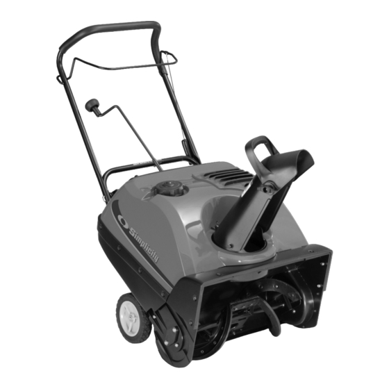
- Page 3 OPERATOR’S MANUAL Single Stage Snowthrower 522E Models Mfg. No. Description 1695468 522E, Snowthrower 1695514 522E, Snowthrower (CE) 1742166-00 Rev 7/2008 TP 100-4961-00-SW-S...
-
Page 5: Table Of Contents
CONTENTS: Safety Rules & Information General ...2 Training ...4 Preparation ...4 Operation ...4 Children...5 Clearing a Clogged Discharge Chute ...5 Service, Maintenance and Storage ...5 Emissions...5 Identification Numbers ...6 Decals ...7 Assembling the Snowthrower ...8 Controls & Operation Snowthrower Controls...10 Engine &... -
Page 6: Safety Rules & Information
Safety Rules & Information Read the Manual The operator’s manual contains important safety information you need to be aware of BEFORE you operate your unit as well as DURING operation. Safe operating techniques, an explanation of the product’s features and controls, and maintenance information is included to help you get the most out of your equipment investment. -
Page 7: Safety Rules And Information
Moving Parts This equipment has many moving parts that can injure you or someone else. However, if you are standing in the operator’s position, and follow all the rules in this book, the unit is safe to operate. The auger and impeller have spinning parts that can amputate hands and feet. Do not allow anyone near the equipment while it is running! DO NOT clear the discharge chute by hand. -
Page 8: Training
Safety Rules & Information This machine is capable to amputating hands and feet and throwing objects. Read these safety rules and follow them closely. Failure to obey these rules could result in loss of control of unit, severe personal injury or death to you, or bystanders, or damage to property or equipment. -
Page 9: Children
21. Keep in mind the operator is responsible for acci- dents occurring to other people or property. 22. Data indicates that operators, age 60 years and above, are involved in a large percentage of power equipment-related injuries. These operators should evaluate their ability to operate the unit safely enough to protect themselves and others from injury. -
Page 10: Identification Numbers
Product Identification Identification Numbers Product Identification Tag Model / Modéle / Model xxxxxxxx Serial / Sèrie / Serie xxxxxxxxxx Briggs & Stratton Power Products Group, L.L.C. Milwaukee, WI 53201 USA Part No. xxxxxxx xxxxxxxxxxxxxxx Serial No. xxxxxxxxxx xxxxxxxxxxxxxxxxxxxxxxx kg: xxx xxxxxxxxxxxxxxxxxxxxxxx kW: x.xx xxxxxxxxxxxxxxxxxxxxxxx... -
Page 11: Decals
SAFETY DECALS Safety warning decals are placed at strategic locations on the snowthrower as a constant reminder to the opera- tor of the most important safety precautions. All warning, caution and instructional messages on your snowthrow- er should be carefully read and obeyed. If any of these decals are lost or damaged, replace them at once. They can be purchased from your local dealer. -
Page 12: Assembling The Snowthrower
Assembling the Snowthrower TOOLS REQUIRED • Knife REMOVAL FROM CARTON 1. Locate and remove container of oil. 2. Locate all parts packed separately and remove from carton. NOTE: Set the fuel stabilizer aside until adding gasoline to the fuel tank. We recommend that fuel stabilizer be added to the fuel each time that gasoline is added to the fuel tank. - Page 13 Figure 3. Z-Hook Installation A. Auger Drive Lever B. Z-Hook C. Auger Drive Cable 2. Attach the auger drive cable (C, Figure 3) to the auger drive lever (A) using the Z-hook (B). 3. Remove the T-knob (B, Figure 4) and bolt on the upper chute.
-
Page 14: Controls & Operation
Controls & Operation SNOWTHROWER CONTROLS Auger Control A. Auger Control - This control engages and disen- gages the auger. Pull the control back against handle to engage the auger, (this will pull snowthrower for- ward if auger is in contact with the ground). Release the Auger Control to stop rotation of auger. -
Page 15: Engine & Starting Controls
ENGINE & STARTING CONTROLS NOTE: This snow thrower does NOT have a throttle for controlling operating speed of engine. The engine gover- nor maintains operating speed for varying snow removal conditions. A. Electric Start Button - The Electric Start Button (A, Figure 8) activates an electric starter mounted to the engine, eliminating the need to pull the starter han- dle. -
Page 16: General Operation
Controls & Operation GENERAL OPERATION CHECKS BEFORE EACH START-UP 1. Make sure all safety guards are in place and all nuts, bolts and clips are secure. 2. Check the fuel supply. Fill the tank no closer than 1/4 to 1/2 inch of top of tank to provide space for expan- sion. -
Page 17: Adding Engine Oil
ADDING ENGINE OIL 1. Make sure the unit is level. Use a high quality deter- gent oil classified “For Service SG, SH, SJ, SL, or higher”. 2. Remove the oil fill cap/dipstick access panel (A, Figure 9). 2. Remove the oil fill cap/dipstick (B) and wipe with a clean cloth. -
Page 18: Starting The Engine
Controls & Operation STARTING THE ENGINE NOTE: The snowthrower engine is designed to operate at cold temperatures. Avoid operating the snowthrower if air temperature is 40° For warmer since engine may vapor lock and stop running after a short time. Engine will be difficult to start in warm weather. -
Page 19: Operating The Snowthrower
OPERATING THE SNOWTHROWER Before operating snowthrower, review the Checks Before Each Use under General Operation on page 12 of this manual. 1. Rotate the discharge chute to the desired direction. 2. Pull the Auger Control back against the handle to engage the auger. -
Page 20: Regular Maintenance
Regular Maintenance WARNING Before beginning any repair stop the engine, remove the key, disconnect the spark plug wire, and wait for all moving parts to stop. LUBRICATION NOTE: The drive pulley end of auger shaft is supported by a sealed ball bearing and requires no lubrication. The ball bearing on other end of auger shaft is also sealed, and will not require lubrication. -
Page 21: Troubleshooting & Service Troubleshooting
Problem Engine fails to start Engine starts hard or runs poorly Unit does not throw snow Auger does not stop turning when control is released Excessive vibration Note: For repairs beyond the minor adjustments listed above, please contact your local dealer. CHUTE REMOVAL AND INSTALLATION 1. -
Page 22: Cover Removal And Installation
Troubleshooting & Service COVER REMOVAL AND INSTALLATION To access the drive system or the engine, the covers must be removed as follows: REMOVE THE TOP COVER 1. Remove the discharge chute. See “Chute Removal and Installation”. 2. Remove the fuel cap. 3. -
Page 23: Replacing The Drive Belt
REPLACE DRIVE BELT The drive belt is of special construction and must be replaced with original factory replacement belt available from your nearest dealer. 1. Remove the belt cover. See “Remove The Belt Cover”. 2. Remove the drive belt (E, Figure 14) from the idler pulley (G). -
Page 24: Servicing The Spark Plug
Troubleshooting & Service SERVICING THE SPARK PLUG 1. Remove engine key from switch. 2. Remove the oil access cover. 3. Disconnect the wire from the spark plug. 4. Inspect the spark plug and clean. If necessary, replace it with a new spark plug as recommended in the engine Owner’s Manual. -
Page 25: Auger Drive Cable Adjustment
AUGER DRIVE CABLE ADJUSTMENT The auger drive cable is adjusted at the factory and no adjustment should be necessary. If the cable becomes stretched or is sagging, adjustment will be necessary. Whenever the belt is adjusted or replaced, the cable will need to be adjusted. -
Page 26: Specifications
9.02 Cu. in (148 cc) Parts & Accessories REPLACEMENT PARTS Replacement parts are available from your authorized dealer. Always use genuine Simplicity Service Parts. MAINTENANCE ITEMS Many convenient and helpful service and maintenance items are available from you authorized dealer. Some of... - Page 28 www.SimplicityMfg.com Briggs & Stratton Power Products Group, L.L.C. Copyright © 2008 Briggs & Stratton Corporation Milwaukee, WI USA. All Rights Reserved www.BRIGGSandSTRATTON.com...