Advertisement
Table of Contents
- 1 Installation Manual
- 2 Table of Contents
- 3 Accessory Parts and Parts to be Procured Locally
- 4 Precautions for Safety
- 5 Installation of New Refrigerant Air Conditioner
- 6 Selection of Installation Place
- 7 Installation and Service Space
- 8 Installation of Flow Selector Unit
- 9 External View
- 10 Drain Piping
- 11 Refrigerant Piping
- 12 Gas Leak Check
- 13 Electrical Connection
- 14 System Wiring Diagram
- Download this manual
Advertisement
Table of Contents

Related Manuals for Toshiba RBM-Y1801F4PE


Summary of Contents for Toshiba RBM-Y1801F4PE
-
Page 1: Installation Manual
Installation Manual Multi Port Flow Selector Unit RBM-Y1801F4PE RBM-Y1801F6PE English INSTALLATION MANUAL... -
Page 2: Table Of Contents
Multi Port Flow Selector Unit (hereafter "Flow Selector unit") Thank you very much for purchasing TOSHIBA Super Heat Recovery Multi (SHRM) Air conditioner. Please read this manual carefully before using your Flow Selector unit. • When installing an indoor or outdoor unit, follow the installation manual supplied with the unit. -
Page 3: Accessory Parts And Parts To Be Procured Locally
Accessory parts and Parts to be procured locally Q'ty RBM-Y1801 Part name Shape Usage F4PE F6PE Accessory parts Heat insulator For insulating drain connecting section Q'ty RBM-Y1801 Part name Shape Usage F4PE F6PE Washer M10 × Ø34 For hanging the unit This manual for installer. -
Page 4: Precautions For Safety
PRECAUTIONS FOR SAFETY • Ensure that all Local, National and International regulations are satisfi ed. CAUTION • Read this “PRECAUTIONS FOR SAFETY” carefully before Installation. • The precautions described below include the important items regarding safety. Observe them without fail. New Refrigerant Air Conditioner Installation •... -
Page 5: Installation Of New Refrigerant Air Conditioner
INSTALLATION OF NEW REFRIGERANT SELECTION OF INSTALLATION PLACE AIR CONDITIONER CAUTION This air conditioner adopts the new HFC refrigerant (R410A) which does not deplete the ozone layer. Do not install the air conditioner at place where combustible gas may leak. •... -
Page 6: Installation Of Flow Selector Unit
INSTALLATION OF FLOW SELECTOR Installation under high-humidity atmosphere In some cases including the rainy season, especially inside of the ceiling may become high-humidity atmosphere UNIT (dew-point temperature: 23 °C or higher). 1. Installation to inside of the ceiling with tiles on the roof 2. -
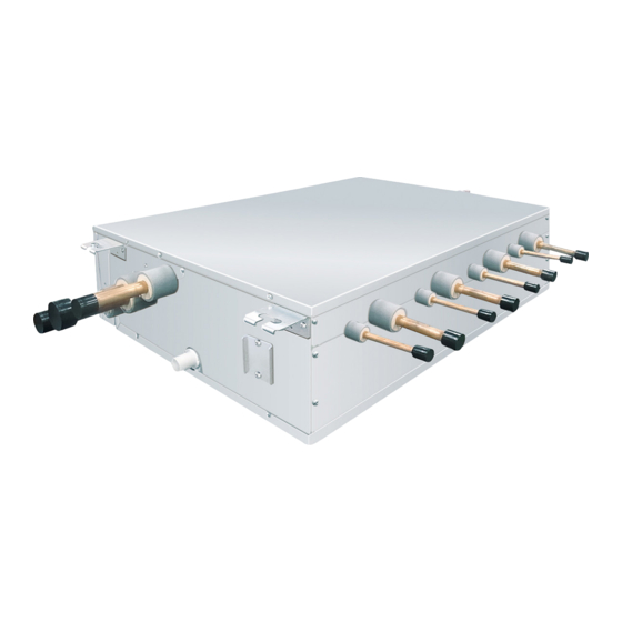
Page 7: External View
Installation of hanging bolt External view Use M10 hanging bolts (4 pcs, locally procured). (Unit:mm) Matching to the existing structure, set pitch according to size in the unit external view as shown below. Control Box New concrete slab Install the bolts with insert brackets or anchor bolts. Discharge gas pipe Suction gas pipe Rubber... -
Page 8: Drain Piping
DRAIN PIPING Connection of drain hose • Insert the attached drain hose into the drain pipe connecting port on the drain pan up to the end. • Fit the attached hose band to the end of the pipe connecting port, and then tighten it securely. CAUTION REQUIREMENT Following the Installation Manual, perform the drain piping work so that water is properly drained. -
Page 9: Refrigerant Piping
REFRIGERANT PIPING Heat insulating process • Using the attached drain hose heat insulator, lap the connecting section and the drain hose without clearance, and then tighten with two handing band so that heat insulator does not open. WARNING • Covering the attached drain hose heat insulator, lap the heat insulator (locally procured) to the drain pipe without clearance. - Page 10 Piping dimensions Pipe connecting process • Connect the pipes. Outdoor unit FS unit • Use stopper-pipe (accessory) to the port to which indoor unit is not connected. Single Indoor unit connection • Use attached-pipe (accessory) to connect the pipe with different diameter from the pipe to Flow Selector unit. per one port Indoor unit downstream...
-
Page 11: Electrical Connection
ELECTRICAL CONNECTION Airtight test/Air purge, etc. For airtight test, air purge, addition of refrigerant, and gas leak check, follow the Installation Manual attached to the outdoor unit. CAUTION REQUIREMENT • If incorrect / incomplete wiring is carried out, it will cause an electrical fi re or smoke. Be sure to use the tool such as charge hose exclusive to R410A. - Page 12 Wire connection U1 U2 U1 U2 U1 U2 Indoor unit REQUIREMENT • Connect the wires matching the terminal numbers. Incorrect connection causes a trouble. • Pass the wires through the bushing of wire connection holes of the Flow Selector unit. •...
- Page 13 See the fi gure on the left for connecting wires to the terminal. Earth wire Communication wire Power supply wire Communication wires Communication wiring Terminal block for remote controller wiring of indoor unit FS unit terminal on PCB Communication wires (locally procured) It's possible to come out the communication wires on the right side.
-
Page 14: System Wiring Diagram
System wiring diagram Outdoor Power supply Outdoor Power supply 380-415 V 3N ~, 50 Hz 380-415 V 3N ~, 50 Hz Circuit breaker Circuit breaker (Earth leakage breaker) (Earth leakage breaker) power switch power switch Header outdoor unit Follower outdoor unit Earth Earth L1 L2 L3 N... - Page 15 Setting when connecting How to set up CODE No. [ 0E ] Caution to connection of indoor unit q Case that FE/FD setting is not necessary indoor units to FS (Flow It is necessary to set up in case of the group control. When connecting the indoor units to FS unit, it is necessary to set up the CODE No..
- Page 16 In case of connecting Drain pump (locally procured) <In case of connecting two group operations of <Incorrect connection examples> indoor units> Incorrect It's available to connect the operation-off signal input cable of fl oat switch. FS unit FS unit Single port type FS unit At that time, the cable is taken from the hole on the control-box bottom side and connect to CN34 on PC board of unit No.1 (showing "1"...
- Page 17 TOSHIBA CARRIER (THAILAND) CO.,LTD. 144/9 MOO 5, BANGKADI INDUSTRIAL PARK, TIVANON ROAD, TAMBOL BANGKADI, AMPHUR MUANG, PATHUMTHANI 12000, THAILAND. 1118430099...