
Related Manuals for Honeywell Wireless Alarm Bar


Summary of Contents for Honeywell Wireless Alarm Bar
-
Page 1: Installation Guide
Wireless Alarm Bar Installation Guide Wireless Alarm Bar Installation Guide Rev. B August 2018 P/N: F08-4007-000... - Page 2 Wireless Alarm Bar Installation Guide Product Registration Register your product online by visiting: http://www.raesystems.com/support/product-registration By registering your product, you can: • Receive notification of product upgrades or enhancements • Be alerted to Training classes in your area • Take advantage of RAE Systems special offers and promotions...
-
Page 3: Table Of Contents
3.1.1. Mounting The Wireless Alarm Bar ................8 3.1.2. Optional Pole Mounting ..................9 3.2. Wireless Alarm Bar Wiring ..................10 3.2.1. Complete Wireless Alarm Bar Wiring Diagram ............. 10 3.2.2. Opening The Junction Box ................... 12 3.2.3. Connecting AC Power (Mains) Wiring ..............13 3.2.4. - Page 4 IMPORTANT! Read Before Installing This Installation Guide is for wiring and installation of the Wireless Alarm Bar only. It must be used in conjunction with the RAEPoint User’s Guide for safe configuration and operation. The RAEPoint User’s Guide is available at www.raesystems.com.
- Page 5 Wireless Alarm Bar Installation Guide Caution This device complies with Part 15 of the FCC Rules / Industry Canada license-exempt RSS standard(s). Operation is subject to the following two conditions: (1) this device may not cause harmful interference, and (2) this device must accept any interference received, including interference that may cause undesired operation.
-
Page 6: General Information
• Fenceline monitoring 2. Purpose Of This Guide This guide is designed to provide information on installing and wiring the Wireless Alarm Bar. Refer to the RAEPoint User’s Guide for testing and operation information (all functions of the RAEPoint Wireless Alarm Bar are controlled through the RAEPoint that is integrated with the horn and strobe... -
Page 7: Flexible Configurations
Wireless Alarm Bar Installation Guide 3. Flexible Configurations The Wireless Alarm Bar can be configured for large or small systems, and the network can be expanded or units removed, depending on the facility or facilities being monitored. Simple configuration that uses MeshGuard sensors and a Wireless Alarm Bar host:... -
Page 8: Wireless Alarm Bar Mounting
476.0 mm/18.75″ Follow these steps: Locate the Wireless Alarm Bar on a wall or other flat surface. Make sure there is at least 12” (30 cm) of clearance around the unit. Mark the mounting holes’ locations. Remove the Wireless Alarm Bar. -
Page 9: Optional Pole Mounting
Wireless Alarm Bar Installation Guide 3.1.2. Optional Pole Mounting If it is not mounted on a wall or other flat surface, the Wireless Alarm Bar can be attached to a pole using optional brackets (Part Number 019-2052-000). Note: The pole must be between 1” (25mm) and 2.5” (63mm) in diameter. -
Page 10: Wireless Alarm Bar Wiring
Wireless Alarm Bar Installation Guide 3.2. Wireless Alarm Bar Wiring The Wireless Alarm Bar already has most wiring done at the factory. It is only necessary to connect the power supply wires and grounding (according to local requirements). Power and internal grounding wires must be fed through a connector at the bottom of the unit. - Page 11 Wireless Alarm Bar Installation Guide...
-
Page 12: Opening The Junction Box
Wireless Alarm Bar Installation Guide 3.2.2. Opening The Junction Box You must remove the cover assembly from the front of the junction box in order to connect wires to the terminal block. Unscrew the four screws on the front of the junction box. -
Page 13: Connecting Ac Power (Mains) Wiring
Note: This diagram only shows the connection points for external power and ground. For clarity, no other wires for the Wireless Alarm Bar are shown. Other wires are already connected to the RAEPoint and the rest of the Wireless Alarm Bar. Do not alter them or their connections. -
Page 14: Reassembly
Tighten the nut and then connect the other end of the ground wire to an appropriate grounding location. Ground wire Threaded post with nut and washers IMPORTANT! Prior to factory shipment, the Wireless Alarm Bar is tested. However, the instrument should be tested after installation. -
Page 15: Powering And Programming
4. Powering And Programming Refer to the RAEPoint User’s Guide for information on how to power, test, and program the RAEPoint. The horn and lights of the Wireless Alarm Bar are prewired, so all operations are controlled by the RAEPoint. -
Page 16: Dc-Powered Wireless Alarm Bar Specifications
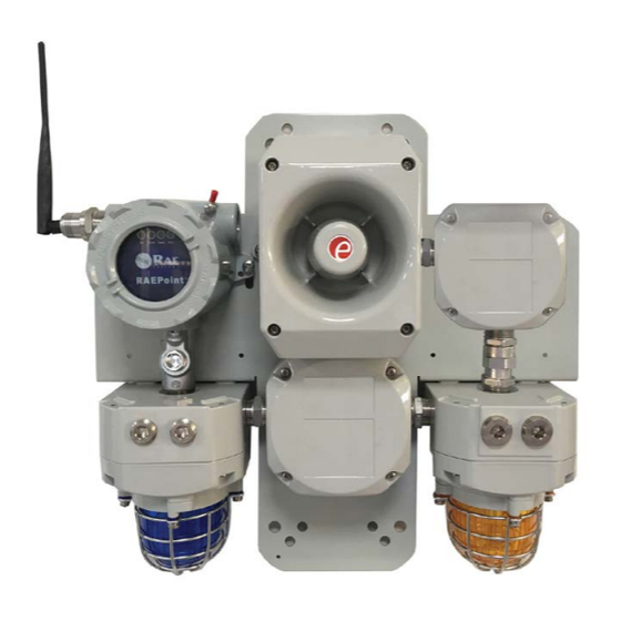
Wireless Alarm Bar Installation Guide 6. DC-Powered Wireless Alarm Bar Specifications The DC-Powered Wireless Alarm Bar includes the RAEPoint, as specified in the RAEPoint User’s Guide, plus two strobe lights and a horn, as detailed below: Input Power 24 to 28VDC, 35W maximum Wireless 2.4GHz... - Page 17 DEALER No: HONEYWELL INTERNATIONAL MIDDLE EAST - LTD - DUBAI BR Hazardous Location Application The Wireless Alarm Bar includes multiple components (RAEPoint, junction box, two strobe lights, and one horn). The table below shows suitable application based on the components for the combined system.
- Page 18 Europe, Middle East, Africa Americas Asia Pacific Life Safety Distribution GmbH Honeywell Analytics Honeywell Analytics Asia Pacific Tel: 00800 333 222 44 (Freephone number) Distribution Inc. Tel: +82 (0) 2 6909 0300 Tel: +41 44 943 4380 (Alternative number) Tel: +1 847 955 8200...