
Related Manuals for Shure FP33


Summary of Contents for Shure FP33
- Page 1 Model FP33 User Guide STEREO ENG MIXER E2003, Shure Incorporated Printed in U.S.A. 27B8500 (CG)
-
Page 2: Table Of Contents
......POWERING THE FP33 MIXER ........ - Page 3 • 1 kHz tone oscillator be used with the FP33. The mixer provides 48 V phantom, • Mix bus jack and cable to link FP33 or FP32A mixers 12 V phantom, and 12 V T (A-B) power for operating con- •...
- Page 4 If the Limiter is switched on, each LED glows FP33 output. The 1 kHz tone mutes all inputs. The tone green to indicate Limiter operation. The LED will still level can be adjusted with the Master control.
-
Page 5: General
• 1 kHz tone oscillator be used with the FP33. The mixer provides 48 V phantom, • Mix bus jack and cable to link FP33 or FP32A mixers 12 V phantom, and 12 V T (A-B) power for operating con- •... -
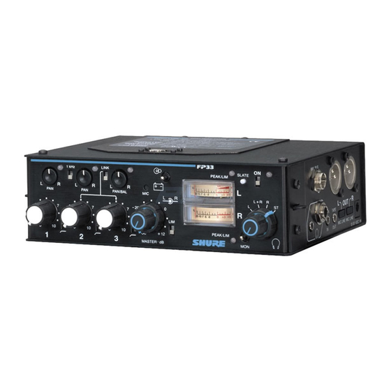
Page 6: Front Panel Controls And Indicators (Figure 1)
If the Limiter is switched on, each LED glows FP33 output. The 1 kHz tone mutes all inputs. The tone green to indicate Limiter operation. The LED will still level can be adjusted with the Master control. - Page 7 Master Level controls. To calibrate other devices, 19. Headphone Monitor Mode Switch (Outer Ring): adjust the Master Level controls for a 0 VU re- The user can monitor the FP33 output as: Stereo; Right sponse. channel only; Mono (Left + Right); or Left channel only.
-
Page 8: Input Panel Connectors And Controls (Figure 2)
Figure 3 OUTPUT PANEL CONNECTORS AND CONTROLS (Figure 3) 1. Mix Bus Jack: Allows an FP33 to be connected to an In signal to the headphones. Program audio is not additional FP33 or FP32A mixer. A mix bus cable is heard in the headphones when this switch is on. -
Page 9: Internal Switches And Controls (Figure 4)
See the Limiter Threshold Adjustment paragraph. phones that do not require T power. Level L Potentiometer: Attenuates the level of the FP33 left channel program audio that is fed to the head- FP33 Input = Microphone Supply Current phone/monitor circuit. This does not affect the Monitor Phantom In levels at the headphone output. -
Page 10: Internal Switches And Controls (Cont.)
Removes slate tone/slate microphone from pre-master cIrcuit. POST-MAST SLATE Inserts slate tone and slate microphone into FP33 circuit after the Master gain control (post-master). Slate level not is controlled by Master. Removes slate tone and slate microphone from FP33 post-master circuit. -
Page 11: Mixer Setup
FP33 outputs. to the On (up) position. Use the tone to set the input 6. If a “tape return” or Monitor In feed into the FP33 is re- level control of the device following the FP33. Once quired, connect a 3.5 mm stereo male plug into the the input level of the following device is set, slide the Mon In connector on the right side panel. -
Page 12: Connecting Fp33 Transformer
FP33 limiter 6. Slowly adjust the trim pot counterclockwise until the threshold set to +4 dBm. Modification of the FP33 output im- left Peak/Lim LED first illuminates red. pedance to 600 Ω is recommended for proper fidelity. (See 7. - Page 13 Increasing Output Level of Slate Mic • X502. Power LED Red Flashing Point • 5. Activate the Monitor In switch. FP33 audio will be atte- Reduction of Headphone Circuit Output Impedance • nuated by the predetermined level. Single Output Level Control •...
-
Page 14: Specifications
......26A19 Output Noise To wrap the carrying case around the FP33 mixer, refer Master level fully CCW: ≤ –100 dBV, 20 to 20,000 Hz. to the assembly instructions supplied. -
Page 15: Statement Of Conformity
1. Reorient or relocate the receiving antenna. Changes or modifications not expressly approved by Shure, Inc., could void your authority to operate this equip- 2. Increase the separation between the equipment and ment. the receiver. - Page 16 SHURE Incorporated Web Address: http://www.shure.com 5800 W. Touhy Avenue, Niles, IL 60714-4608, U.S.A. Phone: 800-257-4873 Fax: 847-600-1212 In Europe, Phone: 49-7131-72140 Fax: 49-7131-721414 In Asia, Phone: 852-2893-4290 Fax: 852-2893-4055 Elsewhere, Phone: 847-600-2000 Fax: 847-600-6446...