Advertisement
Quick Links
Installation Instructions
Models OP121/OH121
Photoelectric Smoke Detector and Photo
Smoke/Thermal Detector
These instructions are written in accordance with the
installation guidelines of NFPA No. 72, National Fire Alarm
Code, and CAN/ULC-S524, The Installation of Fire Alarm
Systems.
DETECTOR PLACEMENT
For a clear air, 0 to 4000 ft/min velocity application, use 30
foot center spacing (900 sq ft) from NFPA Standard 72
initiating devices chapter and CAN/ULC-S524 as a starting
point for a detector installation layout. This spacing, however,
is based on ideal conditions – smooth ceiling, no air
movement, and no physical obstructions. In some
applications, considerably less area is protected adequately
by each smoke detector. In all installations, place the
detector on the ceiling, a minimum of 6 inches from a side
wall, or on a wall, 6 inches from the ceiling.
Follow the drawings provided or approved by Siemens
Industry, Inc. or by its authorized distributors. See NFPA 72,
National Fire Alarm Code, initiating devices chapter for
additional guidance on special issues such as beamed
construction and high stockpiling.
TO AVOID NUISANCE ALARMS:
DO NOT locate the OP121/OH121 detector where
excessive smoke concentrations exist under normal
conditions, or in areas of prolonged high relative humidity
where condensation occurs.
DO NOT locate the OP121/OH121 detector next to an oil
burner, kitchen, or garage where exhaust fumes can trigger
an alarm. Other causes of false alarms are dust
accumulation, heavy concentrations of steam, heavy pipe
or cigar smoke, and certain aerosol sprays.
AIR CURRENTS
Before a detector can sense a fire, the products of com-
bustion or smoke must travel from the fire to the detector.
Since their travel is especially influenced by air currents,
consider the movement of air in the design of the system.
While combustion products tend to rise, drafts from hallways,
air diffusers, fans, etc., may help or hinder the travel of
combustion products to the detector. When positioning a
detector at a particular location, give consideration to
windows and doors, both open and closed, and to influencing
air movement. Never install a detector in the air stream of a
room air supply diffuser. It is better to position a detector
closer to an air return.
A6V10281367_b_en--
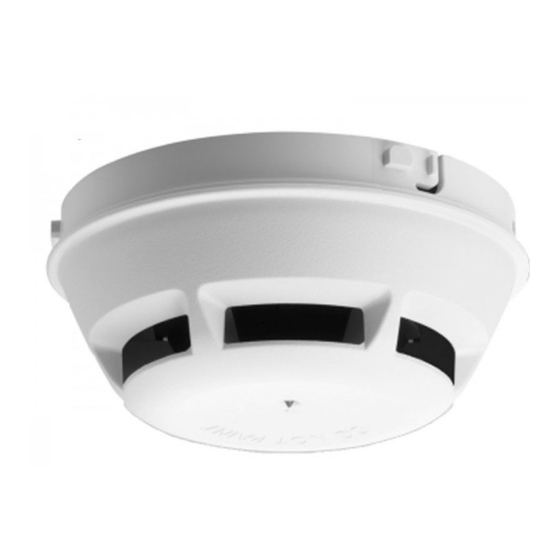
Figure 1 OP121 Photoelectric
Smoke Detector
SPECIFICATIONS
Environmental
Operating Temperature (Model OP121): 32
0
(49
C)
Operating Temperature (Model OH121): 32
0
(38
C)
Humidity: Up to 95% RH, non condensing
Air Pressure: No effect
Air Velocity: 0 to 4000 ft/min. For open area protection and direct
air duct application.
Thermal Alarm Temp. (Model OH121): 135
UL listed with STI Mechanical Protection Guard Model: STI-9604
(see
www.STI-USA.com
Electrical
Voltage:
Ripple:
Supervisory Current:
Alarm Current:
Start-up Time:
DETECTOR WIRING
The OP121/OH121 should be connected as shown in Figure 3 using
the separate mounting base, Model DB-11. Follow the control panel
wiring connection drawing installed on the inside face of each
control panel cover. See DB-11 instruction, P/N 315-094193, for
base mounting. Duplicate wiring information is also in the
Installation, Operation, and Maintenance Manual provided with
every control panel. Note any limitations on the number of
detectors and restrictions on the use of remote devices
permitted for each circuit.
W ARNING: CONNECT DETECTOR ONL Y TO CIRCUITS SPE CIF IE D I N DETECTOR AND P ANEL
L ITERATURE OR SYSTE M M AY NO T OPER ATE.
DB-11/DB-11E
[NO REMOTE DEVICE]
+
1b
TO INITIATING
CIRCUIT OF
1a
1b
SIEMENS
INDUSTRY, INC.
5
6
CONTROL PANEL
6
(SEE CAUTION 1)
5
CAU TION :
1. Do not use looped wire under base
terminal 5. Break wire run to provide
supervision of connection.
2. When a remote relay is used to
control a critical system function, the
relay and its associated detector and
-
optional module(s) must be the ONLY
devices on the initiating circuit.
Figure 3 Installations and Wiring Diagram for OP121/OH121
Conventional Detectors
Building Technologies Division
Figure 2 OH121 Photo Smoke
Thermal Detector
0
0
F (0
C) to 120
0
0
F (0
C) to 100
0
0
F (57
C)
for details)
16-27 VDC
3V peak-to-peak
100
A max
μ
30-50mA
30 seconds max
DB-11/DB-11E
[WITH REMOTE DEVICE(S)]
SEE REMOTE DEVICE INSTRUCTIONS
FOR WIRING DETAILS:
INSTALLATION
DEVICE
INSTRUCTIONS
RR-11
P/N 315-094924
RLC-11, RLW-11
P/N 315-094925
RSAC-11, RSAW-11
P/N 315-094926
ADB-11
P/N 315-096162
MULTIPLE REMOTE DEVICES
If remote devices are supported by the initiating circuit,
each detector/base may have up to 2 remote devices
with the following configurations and restrictions only:
Remote
Remote
Device 1
Device 2
Restrictions
RR-11
RLC-11, RLW-11
See Caution 2
RR-11
RSAC-11, RSAW-11
See Caution 2
RLC-11, RLW-11
RSAC-11, RSAW-11
Wire from base to
RLC-11, RLW-11
RLC-11, RLW-11
RSAC-11/RSAW-11
to RL-11
Siemens, Industry,
0
F
0
F
1b
+
-
5
END OF
LINE
DEVICE
(NOTE
POLARITY
WHEN
APPLICABLE)
Inc.
Advertisement

Related Manuals for Siemens OP121


Summary of Contents for Siemens OP121
- Page 1 The OP121/OH121 should be connected as shown in Figure 3 using the separate mounting base, Model DB-11. Follow the control panel wiring connection drawing installed on the inside face of each TO AVOID NUISANCE ALARMS: control panel cover.
- Page 2 Alarm 2½ shown in Figure 5 for the OP121 detector and Figure 7 for the Detector is not powered or replacement is OH121 detector for at least 5 seconds with the colored side Flashes needed.