Table of Contents
Advertisement
INSTALLATION MANUAL
AIR CONDITIONER
• Please read this installation manual completely before installing the product.
• Installation work must be performed in accordance with the national wiring
standards by authorized personnel only.
• Please retain this installation manual for future reference after reading it
thoroughly.
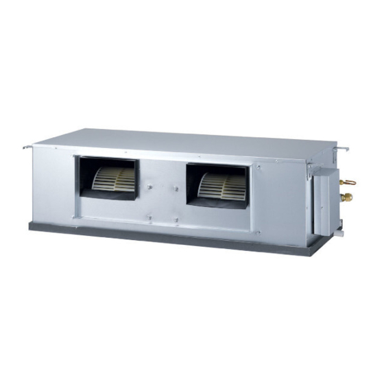
TYPE : CEILING CONCEALED DUCT
MODEL : B62AWYN9L6 / B62AWYU7L6
B70AWYN9L6 / B70AWYU7L6
P/NO : MFL41755815
Original instruction
www.lg.com
LG Electronics Inc. 2 Wonderland Drive,
Eastern Creek, NSW 2766, Australia
LG Electronics Inc. Changwon 2nd factory
84, Wanam-ro, Seongsan-gu,
Changwon-si, Gyeongsangnam-do, KOREA
Advertisement
Table of Contents

Related Manuals for LG B62AWYN9L6


Summary of Contents for LG B62AWYN9L6
- Page 1 • Please retain this installation manual for future reference after reading it thoroughly. TYPE : CEILING CONCEALED DUCT MODEL : B62AWYN9L6 / B62AWYU7L6 B70AWYN9L6 / B70AWYU7L6 www.lg.com LG Electronics Inc. 2 Wonderland Drive, Eastern Creek, NSW 2766, Australia LG Electronics Inc.
-
Page 2: Table Of Contents
TABLE OF CONTENTS TABLE OF CONTENTS INTRODUCTION WIRING Tips for saving energy Electrical Wiring Important safety instructions Precautions when laying power wiring cable Installation process Indoor unit Features Connecting the cable to Outdoor Unit Environment-friendly alternative refrigerant R-410A Communication and Power wiring cable Nomenclature Wiring of main power supply and equip- ment capacity... -
Page 3: Introduction
INTRODUCTION INTRODUCTION Tips for saving energy Here are some tips that will help you minimize the power consumption when you use the air conditioner. You can use your air conditioner more efficiently by referring to the instructions below: • Do not cool excessively indoors. This may be harmful for your health and may consume more electricity. -
Page 4: Important Safety Instructions
INTRODUCTION Important safety instructions READ ALL INSTRUCTIONS BEFORE USING THE APPLIANCE. Always comply with the following precautions to avoid dangerous situations and ensure peak performance of your product WARNING It can result in serious injury or death when the directions are ignored CAUTION It can result in minor injury or product damage when the directions are ignored WARNING... - Page 5 INTRODUCTION • Use a vacuum pump or Inert (nitrogen) gas when doing leakage test or air purge. Do not compress air or Oxygen and do not use Flammable gases. Otherwise, it may cause fire or explosion. - There is the risk of death, injury, fire or explosion. Operation •...
- Page 6 INTRODUCTION CAUTION Installation • Always check for gas (refrigerant) leakage after installation or repair of product. Low refrigerant lev- els may cause failure of product. • Install the drain hose to ensure that water is drained away properly. A bad connection may cause water leakage.
-
Page 7: Installation Process
INTRODUCTION Installation process Indicate clearly who will be responsible for switch setting. Determination of division work Preparation of contract drawings Make connection clearly between outdoor, indoor, remote controller and option. Take account of gradient The foundation must be level even Sleeve and insert work Outdoor unit foundation work of drainage pipe... -
Page 8: Features
INTRODUCTION Features Air intake vents Air outlet vents Remote controller (Accessory) Air outlet vents Air intake vents... -
Page 9: Environment-Friendly Alternative Refrigerant R-410A
INTRODUCTION Environment-friendly alternative refrigerant R-410A CAUTION - The refrigerant R-410A has the property of higher operating pressure in comparison with • The wall thickness of the pipe should R22. comply with the relevant local and na- tional regulations for the designed pres- Therefore, all materials have the characteris- sure 3.8MPa tics of higher resisting pressure than R22... -
Page 10: Installation Place
INSTALLATION PLACE INSTALLATION PLACE Select space for installing outdoor unit, which - If installation site is area of heavy snowfall, will meet the following conditions: then the following directions should be observed. - No direct thermal radiation from other heat •... -
Page 11: Indoor Unit Installation Place
INSTALLATION PLACE Indoor unit installation place - The place shall easily bear a load exceeding four times the indoor unit’s weight. - The place shall be able to inspect the unit. - The place where the unit shall be leveled. - The place shall allow easy water drainage. -
Page 12: Outdoor Unit Installation Place
INSTALLATION PLACE Outdoor unit installation place - If an awning is built over the unit to prevent direct sunlight or rain exposure, make sure that heat radiation from the condenser is not restricted. More than - Ensure that the spaces indicated by arrows 300mm around front, back and side of the unit. - Page 13 INSTALLATION PLACE Obstacle height of discharge side is lower than the unit 1. Stand alone installation [Unit:mm] L ≤ H L ≤ H 2. Collective installation L ≤ H L ≤ H...
-
Page 14: Installation Guide At The Seaside
Sea wind • If you can’t meet above guide line in the seaside installation, please contact LG Electronics for the additional anticorrosion treatment. • Periodic ( more than once/year ) cleaning of the dust or salt particles... -
Page 15: Product Installation
PRODUCT INSTALLATION PRODUCT INSTALLATION Indoor unit installation Case1 Case2 Position of suspension Bolt Position of Console Bolt - Apply a joint-canvas between the unit and - A place where the unit will be leveled and duct to absorb unnecessary vibration. that can support the weight of the unit. - Page 16 PRODUCT INSTALLATION - Insert the set anchor and washer onto the Ceiling suspension bolts for locking the suspension bolts on the ceiling. - Mount the suspension bolts to the set anchor firmly. - Secure the installation plates onto the sus- Drainage hole pension bolts (adjust level roughly) using nuts, washers and spring washers.
-
Page 17: Separating Work Of The Indoor Unit (If Required)
PRODUCT INSTALLATION Separating work of the indoor unit (if required) To install the indoor unit, it can be easily sepa- rated into 2 sections by making it lighter to carry and easier to maneuver through open- ings and in the ceiling. CAUTION Please separate the indoor unit only when necessary. -
Page 18: Checking The Drainage
PRODUCT INSTALLATION ⑤ Re-connect the unplugged cables. The method to rejoin the indoor unit Reassemble the control box cover. is as follows. ① Sub drain pan and the fan deck section to- gether with the 5 screws. ⑥ Carefully replace the fan deck section top cover and secure the cover with the screws. - Page 19 PRODUCT INSTALLATION Caution for gradient of unit and Safety drainage drainage pipe - There is no need to provide a trap for the safety drainage. If the safety drainage pipe is Lay the drainage pipe hose with a downward connected to the main drainage pipe, make inclination so water will drain out.
-
Page 20: Lifting Method Of The Outdoor Unit
PRODUCT INSTALLATION Lifting method of the outdoor unit - When carrying the suspended, unit pass the ropes between legs of base panel under the unit. - Always lift the unit with ropes attached at four points so that impact is not applied to the unit. - Attach the ropes to the unit at an angle of 40°... -
Page 21: The Outdoor Unit Installation
PRODUCT INSTALLATION The outdoor unit installation - Install at places where it can endure the weight and vibration/noise of the outdoor unit. - The outdoor unit supports at the bottom shall have width of at least 100mm under the Unit’s legs before being fixed. -
Page 22: Foundation For Outdoor Unit Installation
PRODUCT INSTALLATION Foundation for outdoor unit Installation - Fix the unit tightly with bolts as shown below so that unit will not fall down due to earthquake or gust. - Use the H-beam support as a base support - Noise and vibration may occur from the floor or wall since vibration is transferred through the installation part depending on installation status. -
Page 23: Pipe Connection
PIPE CONNECTION PIPE CONNECTION Pipe length and the elevation • Single Operation Additional Pipe Size mm(inch) Length A(m) Elevation B(m) Model refrigerant Liquid Standard Max. Standard Max. (g/m) B62AWYU7L6 Ø22.2(7/8) Ø12.7(1/2) B70AWYU7L6 If installed tube is shorter than 15 m, addition- Indoor unit Outdoor unit al charging is not necessary. -
Page 24: Preparation Of Pipe
PIPE CONNECTION Preparation of Pipe Welding - Pipe connections can be done on the front Main cause of gas leakage is defect in flaring side or on the side according to the installa- work. Carry out correct flaring work in the fol- tion environments. -
Page 25: Preparation Work
PIPE CONNECTION Preparation Work - Use Knock Outs of Base Pan of the outdoor unit for Left/Right or Bottom pipe drawing outs. Wet towel <Liquid pipe> <Gas pipe> Removal Area for Liquid/Gas pipe bottom side connections. ※Pictures may differ depending on the model. CAUTION •... -
Page 26: Pipe Drawing Out
PIPE CONNECTION Pipe Drawing Out Method of drawing out pipes on the front side and right side - Proceed with the pipe work as shown in the below figure for front side and right side pipe draw- ing out. Preventing foreign objects form entering •... - Page 27 PIPE CONNECTION Method of drawing out pipes on the rear side - Proceed with the pipe work as shown in the below figure for rear side pie drawing out. Pipe Knock Out for Liquid/Gas pipes ※Pictures may differ depending on the model.
-
Page 28: Thermal Insulation Of Refrigerant Pipe
PIPE CONNECTION Thermal insulation of refrigerant pipe Be sure to give insulation work to refrigerant pipe by covering liquid pipe and gas pipe separately with enough thickness heat-resistant polyethylene, so that no gap is observed in the joint between indoor unit and insulating material, and insulating materials themselves. When insula- tion work is insufficient, there is a possibility of condensation drip, etc. - Page 29 PIPE CONNECTION Penetrations Sleeve Outer wall Outer wall (exposed) Inner wall (concealed) Heat insulating material Lagging Caulking material Band Waterproofing layer Sleeve with edge Penetrating portion on fire Lagging material limit and boundary wall Floor (fireproofing) Roof pipe shaft Mortar or other incombustible caulking Incombustible heat insulation material When filling a gap with mortar, cover the penetration part with steel plate so that...
-
Page 30: Forming The Piping
PIPE CONNECTION Forming the piping Form the piping by wrapping the connecting portion of the indoor unit with insulation material and secure it with two kinds of vinyl tape. - If you want to connect an additional drain hose, the end of the drain outlet should be routed above the ground. -
Page 31: Leakage Test And Evacuation
LEAKAGE TEST AND EVACUATION LEAKAGE TEST AND EVACUATION Air and moisture remaining in the refrigerant system have undesirable effects as indicated below. - Pressure in the system rises. - Operating current rises. - Cooling(or heating) efficiency drops. - Moisture in the refrigerant circuit may freeze and block capillary tubing. - Water may lead to corrosion of parts in the refrigeration system. -
Page 32: Evacuation
LEAKAGE TEST AND EVACUATION Do a leakage test of all joints of the tub- Indoor unit ing(both Indoor unit and outdoor unit) and both gas and liquid side service valves. Bubbles indicate a leak. Be sure to wipe off the soap with a clean cloth. Outdoor unit After the system is found to be free of leaks, relieve the nitrogen pressure by... -
Page 33: Wiring
WIRING WIRING Electrical Wiring Precautions when laying power wiring cable - Follow ordinance of your governmental organization for technical standard related to Use round pressure terminals for connections electrical equipment, wiring regulations and to the power terminal block. guidance of each electric power company. Power wiring cable Round pressure terminal WARNING... -
Page 34: Indoor Unit
WIRING Indoor Unit - Open the control box cover and connect the Remote controller cord and Indoor power wires. - Remove the control box cover for electrical connection between the indoor and outdoor unit. ① (Remove screws - Use the cord clamper to fix the cord. Control terminal board Connection cord between the indoor unit and the outdoor unit... -
Page 35: Connecting The Cable To Outdoor Unit
WIRING Connecting the cable to Outdoor Unit Remove the side panel for wiring connection. Use the cord clamp to fix the cord. Earthing work - Case 1 : Terminal block of Outdoor Unit have mark. Connect the cable of diameter 1.6mm or more to the earthing terminal provided in the control box and do earthing. - Page 36 WIRING Example) Connection of power and communication cable Front side Main power Terminal block Ground wire Hold power cable Hold communication cable Communication cable Power/ Over Ground cable 50mm gap Main Power and Communication Connection Main power Fix firmly not to be Terminal block displaced Insulation sleeves...
-
Page 37: Communication And Power Wiring Cable
WIRING Communication and Power NOTE wiring cable • The figures are based on assumed length of parallel cabling up to 100m. 1) Communication wiring cable For length in excess of 100m the fig- ures will have to be recalculated in - Types : shielding wire direct proportion to the additional length - Cross section : 1.0~1.5mm... -
Page 38: Wiring Of Main Power Supply And Equipment Capacity
WIRING CAUTION CAUTION • If apparatus is not properly earthed then • Some installation site may require there is always a risk of electric shocks, attachment of an earth leakage breaker. the earthing of the apparatus must be If no earth leakage breaker is installed, it carried out by a qualified person. -
Page 39: Field Wiring
WIRING Field Wiring u Example Connection of Communication wiring cable Indoor Unit 50Hz, 1Ø, 220-240V Outdoor Unit 50Hz, 3Ø, 380-415V Power supply Circuit Breaker 3Phase 4Wires [Outdoor Unit] 50Hz 380-415V R S T N (Main Switch) Switch Power supply 1 Phase 50Hz Fuse 220-240V Circuit... -
Page 40: Connecting The Dred To The Outdoor Unit
WIRING Connecting the DRED to the outdoor unit ( Cut the provided Cable from Outdoor unit and Connect Cen2_BL_J to CN_PWR) ODU Dry contact (PQDSBCDVM0) - Remove the Front panel and the cover,control by loosing screw. Tighten a screw at two point as the right. -
Page 41: Wired Remote Controller Installation
WIRING Wired remote controller installation 1 Put the installation paper on the place and determine the position and height of the fixing screws of the deluxe wired remote controller. Yellow - Refer to the printed side of the installation paper. The position of the fixing screws 2 Please connect indoor unit and remote controller using connec-... -
Page 42: Location Of Remote Controller
Yellow WIRING 3 Remove the installation paper before Fixing the Fixing the installing the remote controller so that it remote controller connecting cable can fit into the right place. Supply the power after connecting deluxe wired remote controller. When you need to change wired remote controller, turn off the main power and change it before turn on the main power. -
Page 43: Setting & Test
Model Step CMM Setting Value 32:01 32:02 32:03 32:04 32:05 32:06 32:07 32:08 32:09 32:10 32:11 B62AWYN9L6 B70AWYN9L6 HIGH NOTE 1. Be sure to set the value refering table 1. Unexpected set value will cause mal-function. 2. Table 1 is based at 230V. According to the fluctuation of voltage, air flow rate varies. -
Page 44: Installer Setting - E.s.p Function
SETTING & TEST Installer Setting - E.S.P Function E.S.P function is setting the volume of each air flow. It is for the convenience of installation. It is recommended that you should not use this function while using the wireless remote controller. CAUTION If you set E.S.P incorrectly, the air conditioner may malfunction. - Page 45 SETTING & TEST ESP value Function code, ESP code Move to ESP value setting by pressing button. (It is 000 when delivering from the warehouse.) Press button to setup ESP value. If pressing button long for 3 seconds, it enters into remote (It is possible to setup ESP controller setter setup mode.
-
Page 46: Precaution In Test Running
SETTING & TEST Precaution in test running Connection of power wiring cable - The initial power supply must provide at least 90% of the rated voltage. Connect the power wiring cable to the Otherwise, the air conditioner should not be independent power supply. - Page 47 SETTING & TEST 8) Never fail to equip a leakage breaker where it is wet or moist. 9) The following troubles would be caused by voltage drop-down. - Vibration of a magnetic switch, dam- age on the contact point there of, fuse breaking, disturbance to the nor- mal function of a overload protection device.
-
Page 48: Self-Diagnosis Function
SETTING & TEST Self-diagnosis function Error Indicator • This function indicates types of failure in self-diagnosis and occurrence of failure for air condi- tion. • Error mark is displayed on display window of indoor units and wired remote controller, and 7- segment LED of outdoor unit control board as shown in the table. -
Page 49: Error Indicator (Outdoor)
SETTING & TEST Error Indicator (Outdoor) Outdoor Error Ex) Error 21 (DC Peack) 2 Times 2 Times 2 Times LED01G (RED) 1 Sec. 1 Sec. 1 Sec. 1 Time 1 Time Error 21 LED02G (GREEN) 2 Sec. 2 Sec. Error LED 1 LED 2 Indoor... -
Page 50: Dip Switch Setting
SETTING & TEST Dip switch setting WARNING When you set the dip switch, you should turn off the circuit breaker or shut the power source of the product down. CAUTION • Unless the applicable dip switch is set properly, the product may not work. •... - Page 51 SETTING & TEST Outdoor Unit If you set the Dip Switch when power is on, the change in setting is not applicable. The changing setting is enabled only when Power is reset. 9 10 Dip Switch Function 1 2 3 4 5 6 7 8 9 10 Normal Operation (No Function) 9 10 Forced Cooling Operation...
-
Page 52: Accessory Guide
SETTING & TEST ACCESSORY GUIDE (PQDSB1) Dry Contact(Only AC 24V) - Fix dry contact on the indoor control box Indoor PCB cover. Control box - Connect dry contact(CN-CC) to Indoor PCB(CN-CC) with cable. - Use the DC line hole when connecting the cable to indoor PCB.(Figure 2). -
Page 53: Wlan Module Installation (Pwfmdd101)
- Install WLAN module in a space open on all sides. (Avoid installing it in a blind spot where the signal is weak or blocked.) - Install the unit so that the LG logo in WLAN module face in the direction of Wi-Fi wireless router installed. -
Page 54: Damper Controller(Pbzc80)
ACCESSORY GUIDE Damper Controller(PBZC80) - Open the cover of indoor unit control box and damper controller(Figure 1) - Assemble the damper controller on the cover which is seperated. - Connect the lead wires between main PCB and damper controller.(Figure 2) - Connect the main power cable and actuator cable to damper controller.(Figure 2) - Assemble the damper controller to indoor unit and then assemble cover of damper controller. -
Page 55: Remote Temperature Sensor(Pqrsta0)
ACCESSORY GUIDE Remote Temperature Sensor(PQRSTA0) - After deciding where the remote temperature sensor is installed, decide the location and height of the fixing screws. (Interval between the screws : 60mm). - After removing the control box cover of the indoor unit, Fixing 60mm screws... -
Page 56: Two Wired Remote Controller
ACCESSORY GUIDE Two wired remote controller - All wired remote controllers are displayed on identical information. - Last used wired romote controller has priority on product's movement. - Set one wired remote controller as master,the others as slave.<Figure 1> - The thermistor mode is operated by the wired remote controller set as "master" Wired remote controller Indoor...