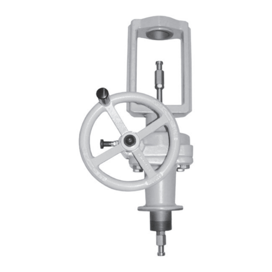
Samson 3273 Mounting And Operating Instructions
Side-mounted handwheel
Hide thumbs
Also See for 3273:
- Mounting and operating instructions (48 pages) ,
- Mounting and operating instructions (44 pages)

Related Manuals for Samson 3273


Summary of Contents for Samson 3273
- Page 1 Type 3273 Side-mounted Handwheel 30 mm rated travel Mounting and Operating Instructions EB 8312-2 EN Edition April 2017...
- Page 2 Î For the safe and proper use of these instructions, read them carefully and keep them for later reference. Î If you have any questions about these instructions, contact SAMSON‘s After-sales Service Department (aftersalesservice@samson.de). The mounting and operating instructions for the devices are included in the scope of delivery.
-
Page 3: Table Of Contents
Contents Safety instructions and measures ..............5 Notes on possible severe personal injury ............7 Notes on possible personal injury ..............8 Notes on possible property damage ..............8 Markings on the device .................8 Nameplate of the side-mounted handwheel .............8 Valve nameplate ....................9 Actuator nameplate ..................9 Design and principle of operation ..............10 Versions ......................11 Technical data .....................12... - Page 4 Contents Decommissioning and disassembly ..............27 Decommissioning ..................27 Removing the handwheel from the actuator and valve ........27 Final steps ....................28 Disposal ......................28 Annex......................29 10.1 After-sales service ..................29 10.2 Spare parts ....................29 EB 8312-2 EN...
-
Page 5: Safety Instructions And Measures
SAMSON. SAMSON does not assume any liability for damage resulting from the failure to use the de- vice for its intended purpose or for damage caused by external forces or any other external factors. - Page 6 Î Check with the plant operator for details on further protective equipment. Revisions and other modifications Revisions, conversions or other modifications to the product are not authorized by SAMSON. They are performed at the user's own risk and may lead to safety hazards, for example. Fur- thermore, the product may no longer meet the requirements for its intended use.
-
Page 7: Notes On Possible Severe Personal Injury
Referenced documentation The following documents apply in addition to these mounting and operating instructions: − Mounting and operating instructions for mounted actuator, e.g. for SAMSON Type 3271 and Type 3277 Actuators: u EB 8310-2 (1000 cm²) (Type 3271 only) u EB 8310-3 (1400-60 cm²) (Type 3271 only) -
Page 8: Notes On Possible Personal Injury
Safety instructions and measures 1.2 Notes on possible personal injury WARNING Crush hazard arising from moving parts. The handwheel contains moving parts (actuator stem, threaded rod, plug stem, hand- wheel), which can injure hands or fingers if inserted into it. Î... -
Page 9: Markings On The Device
Markings on the device 2 Markings on the device 2.1 Nameplate of the side- mounted handwheel It includes all details required to identify the handwheel: Made in Germany SAMSON 3273 Var-ID Serial no. Configuration ID Serial number Year of manufacture Operating travel (mm) -
Page 10: Design And Principle Of Operation
The hand- Handwheel Handle G11 Locking bolt G16 Threaded rod G63 Spindle nut G64 Worm shaft G65 Worm-geared wheel Fig. 3: Sectional drawing of Type 3273 Side-mounted Handwheel EB 8312-2 EN... -
Page 11: Versions
The gear is locked by the locking bolt to pre- vent accidental adjustment. close A close B open B open A Verteilventil Mischventil Diverting valve Mixing valve Vanne de distribution Vanne mélangeuse Fig. 4: Label on handwheel for mounted SAMSON three-way valves EB 8312-2 EN... -
Page 12: Technical Data
Design and principle of operation 3.2 Technical data Table 1: Technical data for Type 3273 up to 30 mm rated travel Version with connection Ø 30 mm Ø 60 mm Type 3273 (see dimensional drawing (see dimensional drawing on p. 13) on p. 14) Rated travel 30 mm 30 mm 1) 1) Max. - Page 13 Design and principle of operation Dimensional drawings · Version with Ø 30 mm connection Ø30 ~133 Ø16 ~292 M30 x 1.5 EB 8312-2 EN...
- Page 14 Design and principle of operation Dimensional drawings · Version with Ø 60 mm connection ~140 Ø60 M60 x 1.5 Ø22 ~298 * For "Actuator stem retracts" direction of action: swap top and bottom stem connector nuts EB 8312-2 EN...
-
Page 15: Measures For Preparation
2. Check the shipment for transportation tire handwheel unit. damage. Report any damage to − When lifting the handwheel unit, make SAMSON and the forwarding agent sure that the slings attached to the yoke (refer to delivery note). bear the entire load. -
Page 16: Lifting
− Observe storage instructions. − Avoid long storage times. To mount the handwheel, use lifting equip- − Contact SAMSON in case of different stor- ment (e.g. crane or forklift) to lift it. age conditions or long storage periods. Lifting instructions −... -
Page 17: Preparation For Installation
Measures for preparation 4.4 Preparation for installation Proceed as follows: Î Remove the actuator first if the valve and actuator have already been assembled without handwheel. See associated actu- ator documentation. Î Check the handwheel for damage. Î Check whether the handwheel (model, travel, thrust, and handwheel diameter) fits the actuator and valve. -
Page 18: Mounting And Start-Up
Excessively tight- Versions with anti-rotation fixture at the plug ened torques lead to parts wearing out stem must only be mounted by SAMSON's quicker. Parts that are not tightened far After-sales Service department or after they enough may loosen. -
Page 19: Mounting The Handwheel Onto The Valve
Mounting and start-up from above and the short stem connector (G26/27). Tighten the hex screws (G29). nut (G71) from below onto the threaded Observe tightening torques. rod. 8. Optionally, a protective bellows (G69) − For "stem retracts" direction of action, can be mounted around the plug stem on screw the short stem connector nut (G71) the valve side. - Page 20 G70 Stem connector nut G71 Stem connector nut Replaces the flange of the valve (2) Replaces the stem connector nut of the valve (9) G26/27 Fig. 5: Type 3273 Side-mounted Handwheel between valve and actuator ("stem extends" direction of action) EB 8312-2 EN...
-
Page 21: Quick Check
5.3 Quick check 7. Slide the ring nut (A8) over the actuator stem (A7) and fasten it on the actuator. SAMSON control valves are delivered ready Observe tightening torques. for use. To test the valve's ability to function, 8. Adjust the rated travel of the actuator e.g. -
Page 22: Operation
Operation 6 Operation The valve position is adjusted by the hand- wheel in manual operation. It can be adjust- Immediately after completing mounting and ed either when the supply air is still applied start-up (see section 5), the handwheel is or has failed or when no pneumatic actuator ready for use. -
Page 23: Working In Manual Operation
Operation 6.2 Working in manual opera- NOTICE tion Risk of valve damage due to the use of ex- cessive force. Do not turn the handwheel any further by NOTICE exerting force after the valve has reached its Risk of handwheel damage due to the use of end position. - Page 24 The handwheel is marked 'Open/Close' and has directional arrows in the version for SAMSON globe valves. A label is affixed to the version for SAMSON three-way valves on the handwheel, which in- dicates in which direction the threaded rod is moved by turning the handwheel (see Table 2).
-
Page 25: Servicing
> Contact. NOTICE 7.2 Ordering spare parts and The handwheel was checked by SAMSON operating supplies before it left the factory. − The product warranty becomes void if Contact your nearest SAMSON subsidiary... -
Page 26: Malfunctions
Depending on the operating conditions, check the handwheel at certain intervals to prevent possible failure before it can occur. Operators are responsible for drawing up an inspection plan. SAMSON's After-sales Service department can support you to draw up an inspection plan for your plant. Troubleshooting... -
Page 27: Decommissioning And Disassembly
Decommissioning and disassembly 9 Decommissioning and disas- 9.1 Decommissioning sembly To decommission the handwheel for mainte- nance and repair work on the valve or for disassembly, proceed as follows: WARNING Crush hazard arising from moving parts. 1. Put the control valve out of operation. The handwheel contains moving parts (actu- See associated valve documentation. -
Page 28: Final Steps
Decommissioning and disassembly 8. Remove the protective bellows (G69). screws (A29). Observe tightening torques. 9. Unscrew the hex screws (G29) at the stem connector clamps (G26/27) be- 9.4 Disposal tween the handwheel and valve. 10. Unscrew the top lock nut (G71) between Î... -
Page 29: Annex
21 Plain bearing Addresses of SAMSON AG and its subsid- 22 Plain bearing iaries 23 Plain bearing The addresses of SAMSON AG, its subsid- 24 O-ring iaries, representatives, and service facilities 25 Bonnet worldwide can be found on the SAMSON website, in all SAMSON product catalogs or... - Page 30 59 Wiper ring 60 Top bonnet (with yoke) 61 Bottom bonnet 62 Screw 63 Spindle nut 64 Worm shaft 65 Worm-geared wheel 70 Stem connector nut 71 Stem connector nut 101 Anti-rotation fixture (optional) 102 Holder (optional) 112 Screw (optional) 113 Screw (optional) 114 Washer (optional) 115 Screw (optional)
- Page 32 SAMSON AG · MESS- UND REGELTECHNIK Weismüllerstraße 3 · 60314 Frankfurt am Main, Germany Phone: +49 69 4009-0 · Fax: +49 69 4009-1507 EB 8312-2 EN samson@samson.de · www.samson.de...