Samson 3271 Mounting And Operating Instructions
Pneumatic actuators
Hide thumbs
Also See for 3271:
- Mounting and operating instructions (76 pages) ,
- Original instructions manual (72 pages) ,
- Manual (32 pages)

Related Manuals for Samson 3271


Summary of Contents for Samson 3271
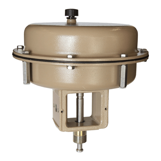
- Page 1 EB 8310-4 EN Translation of original instructions Type 3277 Pneumatic Actuator Types 3271 and 3277 Pneumatic Actuators Actuator area: 355v2 cm² Edition November 2022...
- Page 2 Note on these mounting and operating instructions These mounting and operating instructions assist you in mounting and operating the device safely. The instructions are binding for handling SAMSON devices. The images shown in these instructions are for illustration purposes only. The actual product may vary.
-
Page 3: Table Of Contents
Notes on possible property damage .............1-5 Warnings on the device ................1-6 Markings on the device ................2-1 Actuator nameplate ..................2-1 Design and principle of operation ...............3-1 Type 3271 ....................3-1 Type 3277 ....................3-2 Direction of action ..................3-3 Signal pressure routing ................3-3 3.4.1 Type 3271 ....................3-3 3.4.2... - Page 4 Removal ....................11-1 11.1 Removing the actuator from the valve ............11-2 11.2 Relieving the spring compression in the actuator ..........11-2 Repairs ....................12-1 12.1 Returning devices to SAMSON ..............12-1 Disposal ....................13-1 Certificates ....................14-1 Annex......................15-1 15.1 Tightening torques, lubricants and tools ............15-1 15.2 Spare parts ....................15-1...
-
Page 5: Safety Instructions And Measures
SAMSON. SAMSON does not assume any liability for damage resulting from the failure to use the de- vice for its intended purpose or for damage caused by external forces or any other external factors. - Page 6 Î Check with the plant operator for details on further protective equipment. Revisions and other modifications Revisions, conversions or other modifications of the product are not authorized by SAMSON. They are performed at the user's own risk and may lead to safety hazards, for example. Fur- thermore, the product may no longer meet the requirements for its intended use.
-
Page 7: Notes On Possible Severe Personal Injury
Î For connection to the equipotential bonding system, observe the requirements specified in Clause 6.4 of EN 60079-14 (VDE 0165-1). The Type 3271 and Type 3277 Actuators are partly completed machinery as defined in the Machinery Directive 2006/42/EC or the Directive 2008 No. 1597 Supply of Machinery (Safety) Regulations 2008. -
Page 8: Notes On Possible Personal Injury
Safety instructions and measures 1.2 Notes on possible personal injury WARNING Crush hazard arising from moving parts. The actuator contains moving parts (actuator stem), which can injure hands or fingers if inserted into the actuator. Î Do not touch the actuator stem or insert hands or finger into the yoke or beneath the actuator stem while the air supply is connected to the actuator. -
Page 9: Notes On Possible Property Damage
WARNING Damage to health relating to the REACH regulation. If a SAMSON device contains a substance which is listed as being a substance of very high concern on the candidate list of the REACH regulation, this circumstance is indicat- ed on the SAMSON delivery note. -
Page 10: Warnings On The Device
Risk of actuator damage due to the use of unsuitable lubricants. The lubricants to be used depend on the actuator material. Unsuitable lubricants may corrode and damage surfaces. Î Only use lubricants approved by SAMSON (u AB 0100). 1.4 Warnings on the device Warning... -
Page 11: Markings On The Device
8 Operating travel in mm 9 Operating range in bar 10 Operating range in psi 11 Permissible supply pressure p in bar 12 Permissible supply pressure p in psi Mat: S/N: 11/12 Fig. 2-1: Nameplate of Type 3271 Actuator EB 8310-4 EN... - Page 12 EB 8310-4 EN...
-
Page 13: Design And Principle Of Operation
Design and principle of operation 3 Design and principle of operation The SAMSON Type 3271 and Type 3277 The signal pressure p creates the force F = Actuators with 355v2 cm² actuator area · A at the diaphragm surface A which is are mounted to Series 240, 250, 280 and opposed by the springs (A10) in the actua- 290 Valves (globe valves). -
Page 14: Type 3277
Several springs may be fitted into one anoth- The principle of operation is the same as that The stem connector clamps (A26/27) con- of the Type 3271 Actuator. The Type 3277 nect the actuator stem (A7) with the plug Actuator is fitted with an additional yoke on stem of the globe valve. -
Page 15: Direction Of Action
With direction of action "actuator stem re- In the "actuator stem retracts" version, simi- tracts", the compressed air is applied to the lar to Type 3271, the signal pressure is rout- signal pressure connection on the top dia- ed through the top signal pressure connec- phragm case. -
Page 16: Actuator Stem Extends
Various valve accessories according to − Standard version IEC 60534-6-1 and NAMUR recommenda- The top and bottom diaphragm cases are tion can be mounted on SAMSON control made of plastic-coated sheet steel. valves designed according to the modular − Version with handwheel principle. -
Page 17: Technical Data
It is, however, restricted to cm² number) (item number) 6 bar in throttling service. See the ‘Opera- 100029695 tion’ section for restrictions in on/off service. (included in 3271 scope of de- 1400-5529 livery of the actuator) 3277 100029695 1400-5529 3.8 Technical data... - Page 18 Design and principle of operation Table 3-1: Dimensions in mm and weights in kg Actuator Type 3271 3277 Actuator area cm² 355v2 rated Height – Travel limitation ØD Diameter ØD2 Ød (thread) M30x1.5 M30x1.5 G G a/a1 NPT NPT Air connection –...
- Page 19 Design and principle of operation Dimensional drawings ØD ØD ØD2 ØD2 Ød Ød Type 3271 Type 3277 Type 3271 with travel stop EB 8310-4 EN...
- Page 20 EB 8310-4 EN...
-
Page 21: Shipment And On-Site Transport
Risk of lifting equipment tipping over and damage. Report any damage to risk of damage to lifting accessories due to SAMSON and the forwarding agent exceeding the rated lifting capacity. (refer to delivery note). Î Only use approved lifting equipment and 3. -
Page 22: Transporting The Actuator
Î Observe the storage instructions. equipment (e.g. crane or forklift). Î Avoid long storage times. Î Leave the actuator in its transport con- Î Contact SAMSON in case of different tainer or on the pallet to transport it. storage conditions or longer storage times. - Page 23 Shipment and on-site transport than 75 %. In damp spaces, prevent con- densation. If necessary, use a drying agent or heating. − Make sure that the ambient air is free of acids or other corrosive media. − Observe permissible temperatures (see 'Technical data' in the 'Design and prin- ciple of operation' section).
- Page 24 EB 8310-4 EN...
-
Page 25: Installation
5.2 Mounting the device it has become blocked (e.g. due to seizing up after remaining in the same Depending on the version, SAMSON control position for a long time), release any valves are either delivered with the actuator stored energy in the actuator (e.g. spring already mounted on the valve or the valve compression). -
Page 26: Mounting The Actuator Onto The Valve
Risk of actuator damage due to the use of 2. Firmly press the plug together with the unsuitable tools. plug stem into the seat ring. Î Only use tools approved by SAMSON 3. Thread down the lock nut and stem con- (u AB 0100). nector nut. - Page 27 Hex bolt Threaded bushing Hex nut Stem connector nut Hex bolt (preloading) Lock nut Hex nut (preloading) Travel indicator scale Washer Actuator stem A26/27 Stem connector clamp Ring nut Fig. 5-1: Type 3271 Pneumatic Actuator mounted on a globe valve EB 8310-4 EN...
- Page 28 Installation b) Valve version with anti-rota- actuator onto the valve' section in the as- sociated valve documentation. tion fixture 1. Firmly press the plug together with the plug stem into the seat ring. 2. Anti-rotation fixture not yet mounted onto the valve: Follow the instructions described under 'Mounting the external anti-rotation fix- ture' in the associated valve documenta-...
- Page 29 Installation Actuator stem Valve bonnet Ring nut Stem A26 Stem connector clamps Clamps Screws Fig. 5-2: Anti-rotation fixture: standard version (left) and special version (right) EB 8310-4 EN...
-
Page 30: Connecting The Air Supply
Installation 5.2.2 Connecting the air supply Determine the lower and upper signal pres- sure range values before connecting the sup- ply air: − The lower signal pressure range value is the same as the minimum value of the bench range or operating range (with preloaded springs). -
Page 31: Start-Up
Start-up 6 Start-up WARNING WARNING The work described in this section is only to Risk of personal injury due to exhaust air be performed by personnel appropriately being vented. qualified to carry out such tasks. The actuator is operated with air. As a result, air is vented during operation. -
Page 32: Spring Compression
Start-up longer be correct. This may apply, for exam- − In combination with a SAMSON valve: ple, to the configuration ID or the symbol af- the actuator travel range can be adapted ter reversal of the direction of action. to a smaller valve travel range Î... -
Page 33: Increasing The Actuator Thrust
Start-up 5. Screw the short nuts (A21) with washers The signal pressure for half the actuator trav- (A25) onto the bolts (A20). Observe el (15 mm) is 1.2 bar. Adding it to the lower tightening torques. signal pressure range value of 0.4 bar re- sults in a signal pressure of 1.6 bar required 6.1.2 Increasing the actuator... -
Page 34: Travel Stop
Start-up 6.2 Travel stop See Fig. 6-1 In the version with travel stop, the maximum and minimum actuator travel can be limited as follows: Direction of action Min. stop Max. stop Stem extends (FA) 0 to 125 % 50 to 125 % Stem retracts (FE) 0 to 100 % 50 to 100 % 6.2.1... -
Page 35: Version With Handwheel
Retracting the actuator stem manually 1. Loosen the lock nut to unlock the hand- wheel. 2. Turn the handwheel counterclockwise un- til the top stop position of the overrun Fig. 6-2: Type 3271 Actuator with handwheel mechanism is overcome. EB 8310-4 EN... - Page 36 Start-up EB 8310-4 EN...
-
Page 37: Operation
It is, however, restricted to supply as well as the control signal. 6 bar in throttling service for the Types 3271 Î Do not impede the movement of the and Type 3277 Pneumatic Actuators with actuator stem by inserting objects into 355v2 cm²... -
Page 38: Manual Mode (Versions With Handwheel Only)
Operation Actuator stem retracts (FE) Î Only apply the signal pressure to the sig- nal pressure connection (S) on the dia- For the direction of action "actuator stem re- phragm chamber of the actuator which tracts", the permissible supply pressure must does not contain any springs (see not exceed the upper bench range value by Fig. 3-1 in the 'Design and principle of... -
Page 39: Malfunctions
Malfunctions 8 Malfunctions Read hazard statements, warnings and caution notes in the 'Safety instructions and mea- sures' section. 8.1 Troubleshooting Malfunction Possible reasons Recommended action Actuator stem does not Actuator is blocked. Check attachment. move on demand. Remove the blockage. WARNING! A blocked actuator (e.g. -
Page 40: Emergency Action
Malfunctions 8.2 Emergency action Plant operators are responsible for emergen- cy action to be taken in the plant. EB 8310-4 EN... -
Page 41: Servicing And Conversion
Servicing and conversion 9 Servicing and conversion WARNING WARNING The work described in this section is only to Risk of personal injury due to exhaust air be performed by personnel appropriately being vented. qualified to carry out such tasks. The actuator is operated with air. As a result, air is vented during operation. -
Page 42: Periodic Testing
Risk of actuator damage due to the use of 9.2 Preparation for servicing unsuitable tools. or conversion work Î Only use tools approved by SAMSON (u AB 0100). 1. Lay out the necessary material and tools to have them ready for the intended work. -
Page 43: Mounting The Actuator On The Valve After Servicing Or Conversion Work
Servicing and conversion 9.4 Service work Note To remove an actuator with "stem extends" See Fig. 3-1 and Fig. 3-2 in the 'Design and fail-safe action and/or with preloaded principle of operation' section springs, a certain signal pressure must be 9.4.1 Replacing the dia- applied to the actuator (see the 'Removal' section). - Page 44 Servicing and conversion 8. Screw the collar nut (A15) on the actua- tor stem (A7). Observe tightening torques. 9. Apply a suitable sealant and lubricant to the actuator stem (A7). 10. Insert the actuator stem (A7) together with the diaphragm plate (A5) and dia- phragm (A4) into the bottom diaphragm case (A2).
-
Page 45: Replacing The Actuator Stem Seals
Servicing and conversion b) Actuator stem retracts 12. Place on the top diaphragm case (A1). 13. Fasten the top and bottom diaphragm See Fig. 9-2 cases (A1, A2) together using the nuts 1. Lift off the top diaphragm case (A1). (A21) and bolts (A20). Observe tighten- ing torques. -
Page 46: Conversion Work
Servicing and conversion 9.5 Conversion work 5. Apply a suitable lubricant to the seal lip of the new radial shaft seal. See Fig. 3-1 and Fig. 3-2 in the 'Design and 6. Use a suitable tool to mount the radial principle of operation' section shaft seal. - Page 47 Fig. 9-4: Arrangement of parts with shim for "stem retracts" direction of action cases (A1, A2) together using the nuts (A21) and bolts (A20). Observe tighten- ing torques. 14. Type 3271: remove the vent plug (A16) from the top signal pressure connection EB 8310-4 EN...
- Page 48 Make sure that the ing torques. actuator stem is not damaged. 16. Type 3271: remove the vent plug (A16) 5. Unscrew the collar nut (A15). from the bottom signal pressure connec- 6. Take the compressor (A35) together with...
-
Page 49: Ordering Spare Parts And Operating Supplies
Fig. 9-5: Arrangement of parts for "stem ex- tends" direction of action 9.6 Ordering spare parts and operating supplies Contact your nearest SAMSON subsidiary or SAMSON's After-sales Service for infor- mation on spare parts, lubricants and tools. Spare parts See Annex for details on spare parts. Lubricant See document u AB 0100 for details on... - Page 50 9-10 EB 8310-4 EN...
-
Page 51: Decommissioning
Decommissioning 10 Decommissioning WARNING WARNING The work described in this section is only to Risk of personal injury due to exhaust air be performed by personnel appropriately being vented. qualified to carry out such tasks. The actuator is operated with air. As a result, air is vented during operation. - Page 52 10-2 EB 8310-4 EN...
-
Page 53: Removal
Removal 11 Removal WARNING WARNING The work described in this section is only to Risk of personal injury due to exhaust air be performed by personnel appropriately being vented. qualified to carry out such tasks. The actuator is operated with air. As a result, air is vented during operation. -
Page 54: Removing The Actuator From The Valve
Removal 11.1 Removing the actuator 2. Loosen the long clamping nuts and bolts on the diaphragm cases evenly in a from the valve crisscross pattern to gradually relieve the 1. Undo the clamps of the stem connector spring compression. Hold the bolt head (A26/27). -
Page 55: Repairs
Î Do not perform any repair work on your side of your shipment so that the docu- own. ments are clearly visible. Î Contact SAMSON's After-sales Service 4. Send the shipment to the address given for repair work. on the RMA. - Page 56 12-2 EB 8310-4 EN...
-
Page 57: Disposal
Disposal 13 Disposal Î Observe local, national and internation- al refuse regulations. Î Do not dispose of components, lubricants and hazardous substances together with your household waste. EB 8310-4 EN 13-1... - Page 58 13-2 EB 8310-4 EN...
-
Page 59: Certificates
The declarations of incorporation in compliance with Machinery Directive 2006/42/EC and the Directive 2008 No. 1597 Supply of Machinery (Safety) Regulations 2008 for Type 3271 and Type 3277 Pneumatic Actuators with 355v2 cm² actuator area is provided on the next page. The certificates shown were up to date at the time of publishing. - Page 60 14-2 EB 8310-4 EN...
- Page 61 Type 3271 and Type 3277 Actuators We certify that the Type 3271 and Type 3277 Actuators are partly completed machinery as defined in the in Directive 2008 No. 1597 Supply of Machinery (Safety) Regulations 2008 and that the safety requirements stip- ulated in Annex I, 1.1.2, 1.1.3, 1.1.5, 1.3.2, 1.3.4 and 1.3.7 are observed.
- Page 62 14-4 EB 8310-4 EN...
-
Page 63: Annex
Annex 15 Annex 15.1 Tightening torques, lubricants and tools u AB 0100 for tools, tightening torques and lubricants 15.2 Spare parts Top diaphragm case Actuator stem Bottom diaphragm case Stem connector Diaphragm Screwed flange Diaphragm plate Ring Actuator stem Coupling nut Ring nut Sliding washer Hex nut Yoke... - Page 64 161* 160* Type 3271 15-2 EB 8310-4 EN...
- Page 65 161* 160* Type 3277 EB 8310-4 EN 15-3...
-
Page 66: After-Sales Service
Northern Ireland. Addresses of SAMSON AG and its subsid- Importer iaries SAMSON Controls Ltd The addresses of SAMSON AG, its subsid- Perrywood Business Park iaries, representatives and service facilities worldwide can be found on our website Honeycrock Lane (www.samsongroup.com) or in all SAMSON Redhill, Surrey RH1 5JQ product catalogs. - Page 68 EB 8310-4 EN SAMSON AKTIENGESELLSCHAFT Weismüllerstraße 3 · 60314 Frankfurt am Main, Germany Phone: +49 69 4009-0 · Fax: +49 69 4009-1507 samson@samsongroup.com · www.samsongroup.com...