Advertisement
•
r
i
ii
OWNER'S
MANUAL
MODEL NO.
315.174730
CAUTION:
Read Rules for
Safe Operation
and All Instruc-
tions Carefully
CRn TSMn
Electronic Router
Double Insulated
Thank You for Buying
Craftsman Tools
612547-817
3-95
Warranty
f
Introduction
Operation
Maintenance
Repair Parts
Soldonly by
SEARS, ROEBUCKAND CO., Hoffman Estates, IL 60179
Printed In U.S.A.
Advertisement
Table of Contents

Related Manuals for Craftsman 315.17473


Summary of Contents for Craftsman 315.17473
- Page 1 MANUAL MODEL NO. 315.174730 CAUTION: Read Rules for Safe Operation and All Instruc- tions Carefully Thank You for Buying Craftsman Tools SEARS, ROEBUCKAND CO., Hoffman Estates, IL 60179 612547-817 3-95 • CRn TSMn Electronic Router Double Insulated Warranty Introduction Operation...
-
Page 2: Rules For Safe Operation
FULL ONE YEAR WARRANTY ON CRAFTSMAN ELECTRONIC ROUTER If this CraftsmanElectronicRouter fails to give completesatisfactionwithin one year from the date of purchase RETURN IT TO THE NEAREST SEARS SERVICECENTER / DEPARTMENT THROUGHOUT THE UNITED STATES and Sears willrepair it, free of charge. - Page 3 Illl The operation of any router can result In foreign objects being thrown Into your eyes, which can ! result In severe eye damage. Before beginning powertool operation, always wear safety goggles | or safety glasses with side shields and a full face shield when needed. We recommend Wide | Vision Safety Mask for use over eyeglasses or atandard safety glasses with side shields, i available at Sears Reta!!Stores.
-
Page 4: Operation
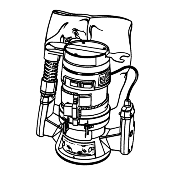
Speed can be set accordingtothe approximatecutterdiameteryou will be usingand to the hardnessof the matedal being cut. Also,the bestcutsare made whenthe cutterisfed through the materialatthe properrate. When possible,you should make practicecutson a scrap pieceof woodto get a "feel" of howfast to "feed =your router. KNOW YOUR ELECTRONIC Beforeattempting to useyourrouter,familiarize yourselfwithall operatingfeatures and safety requirements.See Figure 1. - Page 5 TO TIGHTEN =::_..'__=,,__" DUST BAG ASSEMBLY See Figure 1. Do not connect router to power supply before Installing duet beg or connecting it to • dust collection system. TO INSTALL BAG: , The dustbag ehouldbe installedby slipping it witha twisting moUon overthe blowerexhaust.The bag shouldbe installed...
-
Page 6: Depth Of Cut Adjustments
We recommend that cutsbe madeat a depthnot exceeding 118 in.andthatseveralpassesbe madetoreachdepthsofcut greaterthan 1/8 in. 1. UNPLUG YOUR ROUTER. 2. Place your router on a flat surface, unlock clamping lever, and adjust until cutter is inside subbase. See Figure3. 3. Turn the depth adjustingring untiltip of cutter touches flatsurface. - Page 7 See Figure8. Forease of operationand maintaining propercontrol,your router has twohandles,one on eachside ofthe muterbase. When using your router hold it firmlywith both hands as shownin figure8. Turn muter on and letmotorbuildto itsfull speed, then graduallyfeed cutter into workpiece.Remain alertand watchwhatyou are doing. DO NOT operaterouter whenfatigued.
- Page 8 If you are making a small diameter, shallow groove in soft, dry wood, the proper feed may be about as fast as you can travel your router along your guide line. On the other hand, if the bit is a large one, the cut isdeep or the wood is hard to cut, the proper feed may be a very slow one.
- Page 9 _ TH_ jou,o ROUTING WITH GUIDE When usingtheTemplateGuideBushings ItemNo. 9-25082 with your router,you must visuallycenter the bit with the bushing beforebeginning yourcut. Yourroutersubbasemay be adjustedby loosening the screwsholdingthe subbaseto yourrouter.Be sureclampingleveris securelylockedbefore centedng bit in bushing.After centering bit with bushing tightenscrewsfirmly..
- Page 10 Whenever the workpieca thickness together with the desired depth of cut (as adjusted by router depth setting) are such that only the top part of the edge is to be shaped (leaving at least a 1/16 in.
-
Page 11: Maintenance
Only the partsshownon parts list,page 15, are intendedto be repairedor replaced by the customer. All other parts representan importantpart of the doubleinsulation system and shouldbe serviced only by a qualified Sears service technician. Avoid using solvents when cleaning plastic parts. Most plasticsare susceptible to various types of commercial solventsand may be damaged by their use. -
Page 12: Switch Replacement
SWITCH REPLACEMENT See Figures 15 & 16. 1. UNPLUG YOUR ROUTER. Remove screws (A) and handle cover (B). See Fig. 15. NOTE THE LOCATION OF MOLDED BEND RELIEF (C) ON POWER HANDLE CORD AND ALL WIRING IN HANDLE. ALSO NOTE HOW EACH LEAD IS CONNECTED TO SWITCH. - Page 13 1/2 In. Pan Hd.) should have up to a maximum 114 In. (.250) clearance, allowing flexibility for top screw adjustments. See Figure 19. '-"-- FOLLOWING RECOMMENDED AVAILABLE AT THE TIME THIS MANUAL DovetailTemplate Box JointTemplate Mill-WorksMoldingMaker Bis-KitPlateJointer Kit Multi-Purpose Router Guide STRAIGHT COMB- COMBI. VEINING COREBOX FACE NATION BITS PANEL BITS CUTTER 26326`114"...
- Page 14 Page 14...
-
Page 15: Parts List
NOTE: "A'- The assembly shown represents an Important part of the Double Insulated System. To avoid the possibility of alteration or damage to the system, service should be performed by your nearest Sears Repair Center. Contact your nearest Sears Retail Store. -
Page 16: How To Order Repair Parts
REPAIR THE FOLLOWING INFORMATION: • PART NUMBER • MODEL NUMBER 315.174730 All parts listed may be ordered from any Sears Service Center and most Sears stores. If the parts you need are not stocked will be electronically transmitted Distribution Center for handling.