Table of Contents
Advertisement
s Rs!
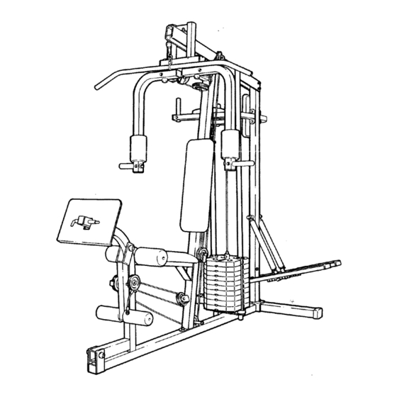
Model No. 831.159310
Serial No.
The serial number can be found in the
location shown below. Write the serial
number in the space above.
Serial Number
Decal
CAUTION!
Read all of the safety precau-
tions and Instructions
in this
owner's
manual
and in the
accompanying
literature
before
using this equipmenL
Keep this
owner's
manual
in a safe place
for future
reference.
CROSS TRAINING
SYSTEM
100
LBS
CONCOR
TM
40+
EXERCISES
TRIAD
TM
LEG
SYSTEM
OWNER'S MANUAL
Advertisement
Table of Contents

Related Manuals for Sears LIFESTULER SYSTEM 40 831.15931


Summary of Contents for Sears LIFESTULER SYSTEM 40 831.15931
- Page 1 s Rs! Model No. 831.159310 Serial No. The serial number can be found in the location shown below. Write the serial number in the space above. Serial Number Decal CAUTION! Read all of the safety precau- tions and Instructions in this owner's manual and in the...
- Page 2 In use. Keep at any t!me while exercising, thls or any exerclse program, over the age of 35 or persons before uslng thls product. SEARS damage sustalned by or through ..Back Cover Back Cover Important...
- Page 3 BEFORE YOU BEGIN Congratulations for selecting the SEARS ative LIFESTYLER SYSTEM 40 offers an impressive array of weight training and aerobic exercises let you enjoy true cross training workouts in the convenience improved cardiovascular fitness, LIFESTYLER SYSTEM 40 wil! help you to achieve the specific results you want!
- Page 4 ASSEMBLY Assembly requires two people and will take about 4 hours. The following required: two 8" adjustable wrenches, screwdriver. Grease and a small bowl of soapy water are also required. cross training system, read each step and examine each drawing are oriented as shown In the drawings.
- Page 5 Slide the Front Upright (76) over the two 5/16" x 2 1/2" Carriage Bolts (22) in the Base (69). Attach the Front Upright Nylock Nuts (4). Do not fully Nylock Nuts until completeing Place the Top Brace (86) on top of the Front and Rear Uprights (76, 74).
- Page 6 Press two 1 3/4" x 1 3/4" Inner Caps (28) into each of the Arms (51). Apply grease to the axles On the Arm Support (85). Slide an Arm (51) onto the right axle. Hold two 1 5/16" Retainer Rings (38) and a 1"...
- Page 7 10. Attach a 3 1/2" "U" Bracket Arm (51) with a 5/16" x 2 1/2" Bolt (20), 3/8" Washer (8) and 5/16" Nylock Nut (4). Do not overtighten the Nylock Nut--the must be able to pivot freely. Attach a Thin "L" Bracket (99) to the 3 1/2" "U"...
- Page 8 Place a Foot Pad (62) on the end of the Right Pedal (64). Attach the Foot Pad with a 1/2" Pan Screw (45). Attach the other Foot Pad (62) to the Left Pedal (63) in the same manner. 15. Apply grease to the cylinder Upright (74).
- Page 9 18. Attach a VKR Armrest (58) to each VKR Arm (57) with two 1/4" x 2' Screws (9) and 1/4" Washers (1). Attach the VKR Backrest (59) to the Rear Upright (74) with two 1/4" x 2 1/2" Screws (2) and 1/4"...
- Page 10 22. Attach the Backrest (76) with two 1/4" x 2 1/2" Screws 1/4" Washers (1). Insert a 3/8" x 2 3/4" Bolt (16) into one side of the Top Brace (86). Slide a 3/8" x 3/8" Metal Spacer (6) onto the Bolt. Lay the ball-end the Short Cable (94) over a 3 1/2"Pulley Slide the Pulley and another Spacer...
- Page 11 26. Route the end of the Short Cable (94) around the indicated 3 1/2" Pulley (55) in the "t" Plates (75). Insert a 3/8" x 2 3/4" Bolt (16) into one side of the Top Brace (86). Slide a 3/8" x 3/8" Metal Spacer (6) onto the Bolt.
- Page 12 Attach a 3" "U" Bracket (97) to the Front Upright (76) with a 5/16" x 4" Bolt (27), 5/16" Washer (10) and 5/16" Nylock Nut (4). The Nylock Nut should be threaded Bolt four complete turns. The cabling be too short If the Nylock ened.
- Page 13 33. Attach a Thick "L" Bracket (100) to the bracket on the Top Brace (86) with a 5/16" x 3 1/4" Bolt (19) and 5/16' Nylock Nut (4). Make sure that the Thick "L" Bracket is turned as shown. Slide a Plastic Cable Guide (18) and a 3 1/2" Pulley (55) onto a 3/8"...
- Page 14 37. Slide the end of the Long Cable (93) onto the end of the 3/8" x 3 1/2" Bolt (5) in the Top Brace (86). Slide a 3/8" Washer (8) onto the Bolt and tighten the 3/8" Jam Nut (7) onto the Bolt.
- Page 15 41. Raise the Weight Selector (82). Place the remaining nine Weights (79) on the Weight Guides (83) by tipping the Weights Make sure that the Weights of the pin grooves are under the Weights are on the same side. Lower the Weight Selector into the Weights.
- Page 16 45. Press a 1" Round Inner Cap (11)into end of the I.at Bar (87). Remove the "HIGH PULLEY" Decal Sheet (not shown). the side of the Top Brace Remove the "DUAL ARM" decal from the Decal Sheet (not shown). Center the decal on the front of the Arm Support (85).
- Page 17 49. Remove the "TRIAD LEG SYSTEM" from the Decal Sheet (not shown). decal to the corner of the Leg Press Plate (70). 50. Remove the ten small decals through "100" from the Decal Sheet (not shown). Apply the decals to the ten Weights (79) in the indicated locations.
- Page 18 52. Make sure that all parts are properly tightened. The use of all remaining parts will be explained USING THE LIFESTYLER WARNING: For your safety and benefit, tem, Before using the cross training system, make sure that both of the cables are properly routed. Pull the ends of both cables a few times to make sure that the cables move smoothly over the pulleys.
- Page 19 USING THE LIFESTYLER The instructions below describe how each part of the cross training system EXERCISE GUIDE accompanying set up for each individual exercise. CHANGING THE WEIGHT SE'n'ING The weight setting of the cross training can be changed from a minimum a maximum of 100 pounds, in increments...
- Page 20 USINGTHEARMS IN THEBUTrERFLY MODE To use the Arms (51) in the butterfly Arm Support (85) must be locked in a stationary position. To lock the Arm Support, "L" Pin (43) down through Support and the bracket Set the other 4 1/2" "L" Pin (43) aside. USING THE ARMS IN THE PRESS To use the Arms (51) in the press mode, the Arms must be locked in a stationary...
- Page 21 TROUBLE-SHOOTING Inspect and properly tighten all parts of the cross training wom parts immediately. The cross training abrasive detergent. Do not use solvents. ADJUSTING THE CABLES If there is too much slack in the cables, cables can be adjusted. To tighten the cables, find the 5/16"...
- Page 22 PART LIST/EXPLODED Part Qty. Description 014127 1/4" Washer 013341 1/4" x2 1/2"Screw 113744 5/16" x 2 3/4" Bolt 012082 5/16" NylockNut 104049 3/8"x3 113745 1/2" x 3/8" Metal Spacer 012108 3/8" Jam Nut 105495 3/8" Washer 013498 1/4" x-2" Screw 014073 5/16"...
- Page 23 |15_ 97 > 4 10...
- Page 24 Each SYSTEM has its own MODEL ing service or repair parts for your SYSTEM. All parts listed herein can be ordered through most SEARS RETAIL STORES. to a SEARS PARTS DISTRIBUTION WHEN ORDERING REPAIR PARTS, ALWAYS 1. The MODEL NUMBER -of the product 2.