Table of Contents
Advertisement
Quick Links
. . . . . . . . . . . . . . . . . . . . . . . . . . . . . . . . . . . . . . . . . . . . .
U10 Family
. . . . . . . . . . . . . . . . . . . . . . . . . . . . . . . . . . . . . . . . . . . . .
ST320423A, ST315323A,
. . . . . . . . . . . . . . . . . . . . . . . . . . . . . . . . . . . . . . . . . . . . .
ST310212A
. . . . . . . . . . . . . . . . . . . . . . . . . . . . . . . . . . . . . . . . . . . . .
Ultra ATA Interface Drives
. . . . . . . . . . . . . . . . . . . . . . . . . . . . . . . . . . . . . . . . . . . . .
Product Manual
. . . . . . . . . . . . . . . . . . . . . . . . . . . . . . . . . . . . . . . . . . . . .
Advertisement
Table of Contents

Related Manuals for Seagate ULTRA ATA ST310212A

Summary of Contents for Seagate ULTRA ATA ST310212A
- Page 1 ..........U10 Family .
- Page 3 ..........U10 Family .
- Page 4 2000 Seagate Technology, Inc. All rights reserved Publication Number: SG35336-001, Rev. A, January 2000 Seagate, Seagate Technology, the Seagate logo and U10 are either registered trademarks or trademarks of Seagate Technology, Inc. Other product names are registered trademarks or trademarks of their owners.
-
Page 5: Table Of Contents
U10 Family Product Manual, Rev. A Contents Introduction ......... . . 1 Specification summary table . - Page 6 1.12.3 FCC verification ......15 2.0 Configuring and mounting the drive ....17 2.1 Handling and static-discharge precautions .
- Page 7 U10 Family Product Manual, Rev. A Figures Figure 1. Typical startup and operation current profile ... . 9 Figure 2. Master/slave jumper settings ..... . . 18 Figure 3.
- Page 8 U10 Family Product Manual, Rev. A...
-
Page 9: Introduction
U10 Family Product Manual, Rev. A Introduction This manual describes the functional, mechanical and interface specifi- cations for the ST320423A, ST315323A and the ST310212A. These drives provide the following key features: • Low power consumption • Quiet operation • High instantaneous (burst) data-transfer rates (up to 66.6 Mbytes per second) using Ultra DMA mode 4 •... -
Page 10: Specification Summary Table
Specification summary table The specifications listed in this table are for quick reference. For details on specification measurement or definition, see the appropriate section of this manual. Drive Specification ST320423A Guaranteed Mbytes ( 10 bytes) Guaranteed sectors 40,011,300 Bytes per sector Default sectors per track Default read/write heads Default cylinders... - Page 11 U10 Family Product Manual, Rev. A Drive Specification ST320423A Full-stroke seek time (msec typical) Average latency (msec) Power-on to ready (sec typical) Standby to ready (sec typical) Spindown (sec typical) Startup current (typical) 12V (peak) Seek power (typical) Read/Write power Idle mode (typical) Standby/Sleep mode (typical) Voltage tolerance...
- Page 12 U10 Family Product Manual, Rev. A Drive Specification ST320423A ST315323A ST310212A Nonrecoverable read errors 1 per 10 bits read Mean time between failures (power-on hours) 500,000 Contact start-stop cycles (25°C, 40% relative humidity) 50,000 Service life (years) SeaShield...
-
Page 13: Drive Specifications
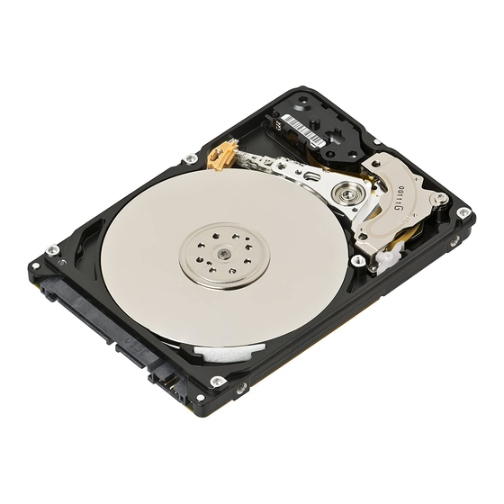
U10 Family Product Manual, Rev. A 1.0 Drive specifications Unless otherwise noted, all specifications are measured under ambient conditions, at 25°C, and nominal power. For convenience, the phrases the drive and this drive are used throughout this manual to indicate the ST320423A, ST315323A and the ST310212A. -
Page 14: Recording And Interface Technology
1.3 Recording and interface technology Interface Recording method Recording density BPI (bits/inch) Track density TPI (tracks/inch) Areal density (Mbits/inch max) Spindle speed (RPM) ( 0.2%) Internal data-transfer rate (Mbits/sec max) I/O data-transfer rate (Mbytes/sec max) Interleave Cache buffer (Kbytes) 1.4 Physical characteristics Drive Specification Maximum height (mm) (inches) -
Page 15: Seek Time
U10 Family Product Manual, Rev. A 1.5 Seek time Seek measurements are taken with nominal power at 25°C ambient temperature. All times are measured using drive diagnostics. The spec- ifications in the table below are defined as follows: • Track-to-track seek time is an average of all possible single-track seeks in both directions. -
Page 16: Power Consumption
1.7.1 Power consumption Power requirements for the drives are listed in the table on page 9. Typical power measurements are based on an average of drives tested, under nominal conditions, using 5.0V input voltage at 25°C ambient temperature. • Spinup power Spinup power is measured from the time of power-on to the time that the drive spindle reaches operating speed. -
Page 17: Figure 1. Typical Startup And Operation Current Profile
U10 Family Product Manual, Rev. A Power Mode Typical Watts Spinup Seeking (Random, no read/write) Operating (read/write) Idle Standby/Sleep 1.7.1.1 Typical current profile Current (amps) Figure 1. Typical startup and operation current profile Typical Amps RMS — 0.65 0.42 0.46 0.350 0.28 0.170... -
Page 18: Conducted Noise
1.7.2 Conducted noise Input noise ripple is measured at the host system power supply across an equivalent 80-ohm resistive load on the +12 volt line or an equivalent 15-ohm resistive load on the +5 volt line. • Using 12-volt power, the drive is expected to operate with a maximum of 120 mV peak-to-peak square-wave injected noise at up to 10 MHz. -
Page 19: Environmental Tolerances
U10 Family Product Manual, Rev. A established using a Standby or Idle command. In Standby mode, the drive buffer is enabled, the heads are parked and the spindle is at rest. The drive accepts all commands and returns to Active mode any time disc access is necessary. -
Page 20: Humidity
1.8.3 Humidity 1.8.3.1 Relative Humidity Operating 5% to 90% noncondensing (30% per hour max) Nonoperating 5% to 95% noncondensing (30% per hour max) 1.8.3.2 Wet bulb temperature Operating 29.4°C (84°F) max Nonoperating 40.0°C (104°F) max 1.8.4 Altitude Operating –61 m to 3,048 m (–200 ft to 10,000+ ft) Nonoperating –122 m to 12,192 m (–400 ft to 40,000+ ft) 1.8.5 Shock... -
Page 21: Drive Acoustics
U10 Family Product Manual, Rev. A 1.8.6.1 Operating vibration The following table lists the maximum vibration levels that the drive may expe- rience while meeting the performance standards specified in this document. 5–21 Hz 0.02-inch displacement (peak to peak) 22–350 Hz 0.5 Gs acceleration (zero to peak) 351–500 Hz 0.25 Gs acceleration (zero to peak) -
Page 22: Electromagnetic Susceptibility
Electromagnetic Compatibility Directives. Testing is performed to standards EN 50082-1 and EN 55022-B. Seagate uses an independent laboratory to confirm compliance with the EC directives specified in the previous paragraph. Drives are tested in representative end-user systems. Although CE-marked Seagate drives U10 Family Product Manual, Rev. -
Page 23: Fcc Verification
Communications Commission verification or certification of the device is required. Seagate Technology, Inc. has tested this device in enclosures as de- scribed above to ensure that the total assembly (enclosure, disc drive, motherboard, power supply, etc.) does comply with the limits for a Class B computing device, pursuant to Subpart J, Part 15 of the FCC rules. - Page 24 U10 Family Product Manual, Rev. A If necessary, you should consult your dealer or an experienced radio/ television technician for additional suggestions. You may find helpful the following booklet prepared by the Federal Communications Commis- sion: How to Identify and Resolve Radio-Television Interference Prob- lems .
-
Page 25: Configuring And Mounting The Drive
U10 Family Product Manual, Rev. A 2.0 Configuring and mounting the drive This section contains the specifications and instructions for configuring and mounting the drive. 2.1 Handling and static-discharge precautions After unpacking, and before installation, the drive may be exposed to potential handling and electrostatic discharge (ESD) hazards. -
Page 26: Jumper Settings
2.2 Jumper settings 2.2.1 Master/slave configuration The options jumper block shown in Figure 2 is used to configure the drive for operation. It is the 6-pin dual header between the interface connector and the power connector. Use the following settings to configure the drive as a master or a slave. -
Page 27: Cable-Select Option
U10 Family Product Manual, Rev. A 2.2.2 Cable-select option Computers that use cable-select determine the master and slave drives by selecting or deselecting pin 28, CSEL, on the interface bus. Master and slave drives are determined by their physical position on the cable. To enable cable select, set a jumper on pins 5 and 6 as shown in Figure 2. -
Page 28: Figure 3. Mounting Dimensions-Top, Side And End View
Note: Dimensions are shown in inches (mm). 1.00 ± 0.028 (25.4 ± 0.7) 0.230 ± 0.015 (5.84 ± 0.38) 3X 6-32 UNC-2B max. insertion depth 0.14 (3.6) both sides 4.000 ± 0.010 (101.60 ± 0.25) 5.75 ± 0.03 (146.1 ± 0.8) 2.362 ±... -
Page 29: Ata Interface
U10 Family Product Manual, Rev. A 3.0 ATA interface These drives use the industry-standard ATA task file interface that supports 16-bit data transfers. It supports ATA programmed input/output (PIO) modes 0–4; multiword DMA modes 0–2, and Ultra DMA modes 0–4. The drive also supports the use of the IORDY signal to provide reliable high-speed data transfers. -
Page 30: Figure 4. I/O Pins And Supported Ata Signals
Drive pin # Signal name Reset – Ground DD10 DD11 DD12 DD13 DD14 DD15 Ground (removed) DMARQ Ground DIOW– STOP Ground DIOR – HDMARDY – HSTROBE Ground IORDY DDMARDY– DSTROBE CSEL DMACK – Ground INTRQ IOCS16 – PDIAG – CBLID– CS0 –... -
Page 31: Supported Ata Commands
U10 Family Product Manual, Rev. A 3.1.1 Supported ATA commands The following table lists ATA-standard commands that the drive sup- ports. For a detailed description of the ATA commands, refer to the Draft ATA-5 Standard. See Section 3.2.4 on page 30 for details and subcom- mands used in the S.M.A.R.T. -
Page 32: Identify Drive Command
Command name Write Multiple Write Sectors ATA-standard power-management commands Check Power Mode Idle Idle Immediate Sleep Standby Standby Immediate ATA-standard security commands Security Set Password Security Unlock Security Erase Prepare Security Erase Unit Security Freeze Lock Security Disable Password 3.1.2 Identify Drive command The Identify Drive command (command code EC about the drive to the host following power up. - Page 33 U10 Family Product Manual, Rev. A Word Description Configuration information: Bit 15: 0 = ATA; 1 = ATAPI • Bit 7: removable media • Bit 6: removable controller • Bit 0: reserved • Number of logical cylinders ATA-reserved Number of logical heads Retired Retired Number of logical sectors per...
- Page 34 Word Description Standard Standby timer, IORDY supported and may be disabled Device-specific standby timer value PIO data-transfer cycle timing mode Retired Words 54–58, 64–70 and 88 are valid Number of current logical cylinders Number of current logical heads Number of current logical sectors per logical track 57–58 Current capacity in sectors...
- Page 35 U10 Family Product Manual, Rev. A Word Description Recommended multiword DMA transfer cycle time per word (120 nsec) Minimum PIO cycle time without IORDY flow control (240 nsec) Minimum PIO cycle time with IORDY flow control (120 nsec) 69–74 ATA-reserved Queue depth 76–79 ATA-reserved...
- Page 36 Hardware Reset Value (see description following this table) 94–127 ATA-reserved Security Status 129–159 Seagate-reserved 160–254 ATA-reserved Integrity word Note. See the bit descriptions below for words 63, 88 and 93 of the Identify Drive data: Description (if bit is set to 1) Word 63 Multiword DMA mode 0 is supported.
-
Page 37: Set Features Command
U10 Family Product Manual, Rev. A Ultra DMA mode 1 is currently active. Ultra DMA mode 2 is currently active. Ultra DMA mode 3 is currently active. Ultra DMA mode 4 is currently active. Word 93 1=80-conductor cable detected, CBLID above V 0=40-conductor cable detected, CBLID below V 3.1.3 Set Features command This command controls the implementation of various features that the... -
Page 38: Commands
Ultra DMA mode 2 Ultra DMA mode 3 Ultra DMA mode 4 Enable advanced power management. Disable read look-ahead (read cache) feature. Disable write cache. Enable read look-ahead (read cache) feature (default). Note. At power-on, or after a hardware or software reset, the default values of the features are as indicated above. - Page 39 U10 Family Product Manual, Rev. A Code in Features S.M.A.R.T. Command Register S.M.A.R.T. Enable Operations S.M.A.R.T. Disable Operations S.M.A.R.T. Return Status Note. If an appropriate code is not written to the Features Register, the command is aborted and 0x04 (abort) is written to the Error register.
- Page 40 U10 Family Product Manual, Rev. A...
- Page 41 U10 Family Product Manual, Rev. A...
- Page 42 U10 Family Product Manual, Rev. A Seagate Technology, Inc. 920 Disc Drive, Scotts Valley, California 95066, USA Publication Number: SG35336-001, Rev. A, Printed in USA...