Advertisement
Quick Links
9506038
9506929
6160029
9506930
9507070
9507098
9507749
Form No: 5903807 Rev: B
Date of Publication: 06/29/2016
Machinery
2006/42/EC
Electrical Safety
BS EN 60335-1:2002
+ A15:2011
EMC
EN 61000-6-1:2007
EN 61000-6-3:2007
+ A1:2011
EN 61000-3-3:2008
EN 61000-3-2:2006
+ A2:2009
6160024
6160051
User Instruction Manual
POWERED CLIMB ASSIST SYSTEM
1
6160024
9506038
9506929
9506930
9507098
6160026
Table 1 – Powered Climb Assist System Components
1
6160024 & 6160026 Cable Grips
Cable Grip
Zinc Plated Alloy Steel
Lanyard
Nylon, Elastic Web
6160026
Carabiners
Zinc Plated Alloy Steel,
3,600 lb. (16 kN) Gate
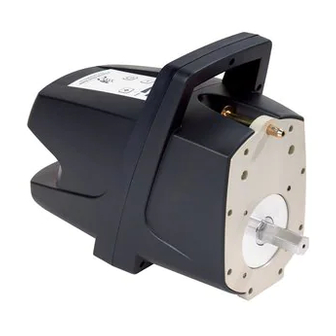
6160025 - Portable Motor Control Unit
Weight
20 lb (9 kg)
Power Supply Range
110 - 240 VAC, 50-60 Hz
Climb Assist Force Range
55 - 120 lb (25 - 55 kg)
Motor Control Panel Functions
Press to switch power ON/OFF.
Press to decrease Climb Assist Force.
Press to increase Climb Assist Force
Press and hold Plus and Minus buttons to
switch the direction of cable travel. Left
LED should illuminate for systems with
the Drive Bracket opposite the climber.
Right LED should illuminate for systems
with the Drive Bracket on the same side
as the climber.
Power Cord, BS 546 Type M
South Africa, India
Power Cord, NEMA 5-15P
United States, Canada, Mexico
Power Cord, AS 3112
Australia, New Zealand, China
Power Cord, CEE 7/7
Europe
© Copyright 2016, 3M
Advertisement

Related Manuals for 3M DBI SALA 9506038


Summary of Contents for 3M DBI SALA 9506038
- Page 1 United States, Canada, Mexico 9506930 Power Cord, AS 3112 Australia, New Zealand, China 9507098 Power Cord, CEE 7/7 Europe 6160024 6160026 6160051 9506038 9506929 6160029 9506930 9507070 9507098 9507749 Form No: 5903807 Rev: B © Copyright 2016, 3M Date of Publication: 06/29/2016...
- Page 4 ...
- Page 5 Original Instructions WARNING: This product must be used in conjunction with a Fall Arrest System. The user must follow the manufacturer’s instructions for each component of the system. These instructions must be provided to the user of this equipment. The user must read and understand these instructions before using this equipment.
-
Page 6: Pinch Points
APPLICATIONS PURPOSE: The Powered Climb Assist System (PCAS) provides powered climb assistance while ascending or descending a ladder. The PCAS is intended for use on interior fi xed ladders, such as those used in Wind Turbine Towers. IMPORTANT: The PCAS should be used only as directed. It is not intended for lifting tools, equipment, spare parts, etc. TRAINING: It is the responsibility of the users and purchasers of this equipment to assure they are familiar with these instructions, trained in the correct care and use of, and are aware of the operating characteristics, application limitations, and consequences of improper use of this equipment. - Page 7 CONNECTOR COMPATIBILITY: Connectors are considered to be compatible with connecting elements when they have been designed to work together in such a way that their sizes and shapes do not cause their gate mechanisms to inadvertently open regardless of how they become oriented. Contact Capital Safety if you have any questions about compatibility.
-
Page 8: System Use
SYSTEM USE IMPORTANT: Do not alter or intentionally misuse this equipment. Consult DBI-SALA when installing or using this equipment in combination with components or subsystems other than those described in this manual. Some subsystem and component combinations may interfere with the operation of this equipment. - Page 9 PCAS TROUBLESHOOTING: The following PCAS Troubleshooting Chart can be used to diagnose and correct system performance issues. If problems persist, contact Capital Safety. PCAS Troubleshooting Chart Symptom: What to Check: Corrective Action: The Motor Control Unit will not Are you pressing in the Detent Pin when See Section 3.2 for Portable Motor mount on the Drive Bracket.
- Page 10 Table 2 – Inspection and Maintenance Log Serial Number(s): Date Purchased: Model Number: Date of First Use: Inspection Date: Inspected By: Competent Component: Inspection: User Person (See Section 1 for Inspection Frequency) Cable Grip Inspect the Cable Grip for cracks, bends, or other deformities that might affect (Diagram 1) performance.
- Page 11 Corrective Action/Maintenance: Approved By: Date: Corrective Action/Maintenance: Approved By: Date: Corrective Action/Maintenance: Approved By: Date: Corrective Action/Maintenance: Approved By: Date: Corrective Action/Maintenance: Approved By: Date: Corrective Action/Maintenance: Approved By: Date: Corrective Action/Maintenance: Approved By: Date: Corrective Action/Maintenance: Approved By: Date: Corrective Action/Maintenance: Approved By: Date:...
-
Page 12: Warranty
WARRANTY WARRANTY FOR MOTOR CONTROL UNIT: Note that the Motor Control Unit of the Powered Climb Assist System is subject to a limited warranty of three (3) years, whereas all other components of the System are subject to Capital Safety’s standard limited lifetime warranty. POWERED CLIMB ASSIST SYSTEM: Warranty to End User - CAPITAL SAFETY warrants to the original end user (“End User”) that its products are free from defects in materials and workmanship under normal use and service. - Page 13 POWERED CLIMB ASSIST www.capitalsafety.com...
- Page 15 Declaration of Conformity SGS United Kingdom Limited Bowburn South Industrial Estate, Durham, Co Durham, DH6 5AD. Place: Red Wing, Minnesota, USA J Thomas Wolner...
- Page 16 Canada Australia & New Zealand 3833 SALA Way 260 Export Boulevard 95 Derby Street Red Wing, MN 55066-5005 Mississauga, ON L5S 1Y9 Silverwater Toll Free: 800.328.6146 Phone: 905.795.9333 Sydney NSW 2128 Phone: 651.388.8282 Toll-Free: 800.387.7484 Australia Fax: 651.388.5065 Fax: 888.387.7484 Phone: +(61) 2 8753 7600 solutions@capitalsafety.com info.ca@capitalsafety.com...