Table of Contents
Advertisement
Advertisement
Table of Contents

Related Manuals for NCR XR3 (7613)

Summary of Contents for NCR XR3 (7613)
- Page 1 User Guide NCR RealPOS (7613) Release 1.0 BCC5–0000–5154 Issue B...
- Page 2 NCR, therefore, reserves the right to change specifications without prior notice. All features, functions, and operations described herein may not be marketed by NCR in all parts of the world. In some instances, photographs are of equipment prototypes. Therefore, before using this document, consult with your NCR representative or NCR office for information that is applicable and current.
- Page 3 Audience This book is written for hardware installer/service personnel, system integrators, and field engineers. Notice: This document is NCR proprietary information and is not to be disclosed or reproduced without consent. Safety Requirements The NCR RealPOS XR3 (7613) conforms to all applicable legal requirements. To view the...
- Page 4 Warning: DO NOT connect or disconnect any serial peripherals while the terminal is connected to AC power. This can result in system or printer damage. Grounding Instructions In the event of a malfunction or breakdown, grounding provides a path of least resistance for electric current to reduce the risk of electric shock.
- Page 5 If you do not have access to a computer, you may leave a voice message at: 1-800-528- 8658 (USA), or (International) +1-770-623-7400. When leaving a message, please provide a phone number and/or an email address so NCR can contact you if additional details are needed.
- Page 6 • Description of the problem, including any system error codes, error condition, or guidance to the area of failure. The NCR Agent will provide you with a work order number, which serves as your Return Material Authorization (RMA). Please provide the RMA on the outside of the shipping box.
-
Page 7: Table Of Contents
Table of Contents Chapter 1: Product Overview Introduction Product IDs Mounting Configuration Operator Controls Power Switch Front Panel Power LED I/O Panel LED Diagnostic Indicators Label Locations Features Operating Systems Display Specifications Integrated Options Customer Displays 2x20 Customer Display (7613-F450, 7613-K450) 10-in Integrated Non-Touch LCD (7613-F452) Cable Management Bar (7613-F500) Wireless Card and Antenna (7613-F153) - Page 8 Connecting the Cash Drawer Single Cash Drawer Dual Cash Drawer Chapter 3: Operation and Cleaning Out-of-Box Powering Up Administrator Login Brightness Adjustment Brightness Control Application RSM LE Interface Touchscreens Projected Capacitive Touchscreen Using the PCap Touchscreen Resistive Touchscreen Using the Resistive Touchscreen Touchscreen Cleaning Procedures Magnetic Stripe Reader Using the MSR...
- Page 9 Change Settings Change Network Settings Change Password Chapter 5: Power Management Computer States G3 Mechanical Off G2/S5 Soft Off G1 Sleeping G0 Working ACPI Sleep States (S0 - S5) Enabling Wake on LAN ACPI Processor C-States Chapter 6: BIOS Setup Entering Setup How to Select Menu Options Restoring Factory Settings...
- Page 10 viii Retail Display Commands Reset Display Erase Display Set Diagnostic State On Select Character Set n Set Low Power State On Enable Cursor Disable Cursor Set Screen Save Blank Set Screen Save Walk Turn On Screen Save Disable Screen Save Option Enable Character Blink Disable Character Blink Move Cursor Left...
- Page 11 Appendix B: Touchscreen Calibration Proper Touchscreen Methods Calibrating the Touchscreen Resistive Touchscreen Calibration...
- Page 12 Revision Record Issue Date Remarks Feb 2017 First Issue Jan 2018 Added Troubleshooting: Terminal Unresponsive After Connecting AC Power...
-
Page 14: Introduction
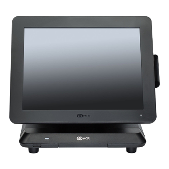
The XR3 is an integrated POS that is also a 3-in-1 product. The XR3 design leverages the combination of the NCR RealPOS XR4 (7602) and NCR XL15 (5915) to deliver a stylish integrated POS. The XR3 is available with a 15-inch resistive or PCAP touch display. A range of configurable options permit integration of a magnetic stripe reader (MSR), wireless module, and a family of customer-facing displays. -
Page 15: Product Ids
Product Overview Product IDs Product ID Description 7613-1215- RealPOS XR3 15" PCAP Display w/ Intel Celeron Dual Core 8801 7613-1225- RealPOS XR3 15" Resistive Display w/ Intel Celeron Dual 8801 Core Note: Storage devices, memory, power supply are ordered as features. -
Page 16: Mounting Configuration
Product Overview Mounting Configuration The NCR RealPOS XR3 is configured to be mounted on a countertop. -
Page 17: Operator Controls
Product Overview Operator Controls Power Switch The Power Switch is located on the Front Panel of the POS. -
Page 18: Front Panel Power Led
Product Overview Front Panel Power LED The Front Panel Power LED has multiple functions as defined below. Color Description System OFF or No power, No Video Signal Green System ON System SLEEP... -
Page 19: O Panel Led Diagnostic Indicators
Red (Solid) BIOS loaded, executing POST Red (Blinking) BIOS Error, POST halted Green (Solid) BIOS POST completed, OS loading, or System Locked Green (Blinking) OS & NCR Drivers loaded and running Power Off No power Orange S5 Standby Green Power On... -
Page 20: Label Locations
Product Overview Label Locations... -
Page 21: Features
Product Overview Features Feature Description Processor Intel® Celeron® Processor N3060 Dual Core Memory • Support for 2 x 204 pin DDR3L SODIMMs, 1333/1600MT/s unbuffered • Standard 4GB DDR 1600MHz • Support for up to 8 GB DDR3 1600MHz • 120GB Solid State Drive (SSD) Storage •... - Page 22 Product Overview Feature Description Supported • US Power Cord Power • International Power Cord Cords • UK Power Cord • Australia Power Cord • China Power Cord • SEV Power Cord • India Power Cord • Argentina Power Cord • Power Cord 120V Twist Lock...
-
Page 23: Operating Systems
System must be configured with hard disk or solid state drive. OS images do not include OPOS driver software for retail peripherals. Windows OPOS drivers are installed using NCR Retail Platform Software for Windows. RPSW Platform software may be ordered on CD-ROM or is downloadable from the NCR Drivers &... -
Page 24: Display Specifications
(64 bit) Embedded Operating Embedded System will be preloaded at the Systems factory Base client and third-party software are also available on the public NCR Platform Software Website: http://www.ncr.com/support/support_drivers_patches.asp?Class=External\display Display Specifications Display Specifications Description Screen Diagonal 15 inches... -
Page 25: Integrated Options
• Integrated 2x20 Customer Display • 10-inch Integrated LCD • Cable Management Bar • Wireless Card and Antenna – 802.11 B/G/N Bluetooth • NCR-Encrypted 3-Track MSR Specific details on each of the options listed are provided in the sections that follow. -
Page 26: Customer Displays
Product Overview 1-13 Customer Displays 2x20 Customer Display (7613-F450, 7613-K450) The 2x20 Customer Display option is configured with a stand mount bracket and cable. 10-in Integrated Non-Touch LCD (7613-F452) The 10-inch LCD option includes the LCD, mount, and cables. -
Page 27: Cable Management Bar (7613-F500)
1-14 Product Overview Cable Management Bar (7613-F500) The Cable Management Bar option neatly secures cables below the terminal. -
Page 28: Wireless Card And Antenna (7613-F153)
1-15 Wireless Card and Antenna (7613-F153) The NCR 7613 features an integrated internal wireless and Bluetooth 4.0 option. The wireless option is Dual-Stream, Dual-Band 802.11 B/G/N. It delivers up to 300 Mbps speed with dual stream (2x2). Bluetooth 4.0 (Low Energy) is also supported in this module. -
Page 29: Magnetic Stripe Reader (7613-F141)
Product Overview Magnetic Stripe Reader (7613-F141) The NCR 7613 provides an integrated 3-track ISO MSR option. The MSR is mounted on the right side of the display. When the MSR is not installed, a cover for the MSR location is included to make the unit appear uniform. The MSR interfaces to the system via a USB connection in the base. -
Page 30: Card Data Encoding
Product Overview 1-17 Card Data Encoding Card data should be encoded according to the ISO Standards 7810, 7811, 7812, and 7813. In particular, 7810 describes the physical dimensions and layout of the card and mag stripe. 7811/1-5 relate to the locations and magnetic characteristics of track data in the mag stripe. -
Page 31: Odometers
The NEXT time an NCR technician goes on site to resolve an incident, they are be informed that the module is due for replacement and they replace that module while on-site. -
Page 32: Installation Restrictions
Statements (B005-0000-1589). • Install the NCR RealPOS XR3 near an electrical outlet that is easily accessible. Use the power cord as a power disconnect device. • Do not permit any object to rest on the power cord. Do not locate the NCR RealPOS XR3 where the power cord can be walked on. -
Page 33: Ergonomic Workplace
Hardware Installation Ergonomic Workplace The NCR RealPOS XR3 has a high brightness LCD, but for best results please observe the following when considering the terminal workplace. • Avoid direct glaring and reflective glaring light. Locate the terminal in a controlled luminance surrounding. -
Page 34: Installing The Terminal
This chapter explains how to perform an "Out-of-box" installation of an NCR RealPOS XR3 on a countertop and how to connect optional peripheral devices. The NCR RealPOS XR3 terminal comes fully assembled and ready to use. All that is required to install the terminal is connect the Peripheral Cables, LAN Cable, Power Adapter Cable, and AC Power Cord. - Page 35 2-22 Hardware Installation 3. Lay the terminal face down on a flat surface. Caution: Always use a soft material (cloth, foam) to protect the display screen when placing the terminal face down.
- Page 36 Hardware Installation 2-23 4. Open the IO Panel Cover. Press on the ribs on both sides, and then pivot the cover to open.
- Page 37 2-24 Hardware Installation 5. Connect the peripheral cables. The available peripheral cable connectors on the IO panel are labeled in the illustration below. a. Route the cable from the back of the terminal towards the IO Panel. Note: If a Cable Management Bar is present, route the cable under the Bar before connecting the cable to the IO Panel.
- Page 38 7. Connect the Power Adapter Cable to the DC Power connector on the terminal. Caution: The NCR 7613 requires the NCR 24 V power supply that is shipped with the terminal. Use of other power bricks may cause damage to the unit.
-
Page 39: Troubleshooting: Terminal Unresponsive After Connecting Ac Power
2-26 Hardware Installation Troubleshooting: Terminal Unresponsive After Connecting AC Power If the cautions are not regarded during powering on the terminal a power on error could occur. The terminal may appear dead or unable to power on. Follow the previous steps to plug in the terminal, wait 60 seconds, and re-attempt powering on the terminal. -
Page 40: Connecting The Transaction Printer
Hardware Installation 2-27 Connecting the Transaction Printer 1. Connect the Powered USB Printer Interface Cable to the USB Connector and Power Connector on the printer 2. Connect the other end of the Printer Cable to the 24 V Powered USB Connector on the terminal. -
Page 41: Connecting The Cash Drawer
2-28 Hardware Installation Connecting the Cash Drawer The NCR RealPOS XR3 supports both single and dual Cash Drawer connections. The Cash Drawer can be connected to the Cash Drawer connector or to the transaction printer. Single Cash Drawer... -
Page 42: Dual Cash Drawer
Hardware Installation 2-29 Dual Cash Drawer The terminal supports a 2-drawer configuration with a Dual Cash Drawer Cable. Connect this cable to the terminal or transaction printer cash drawer connector. There are two versions of the Dual Cash Drawer Cable: •... -
Page 43: Out-Of-Box Powering Up
Operation and Cleaning Chapter 3: Out-of-Box Powering Up 1. After installing the terminal, power up the system by pressing the Power Switch, which is located on the Front Panel of the POS. The system installs the system devices, system settings, and then reboots to continue setup. -
Page 44: Administrator Login
3-31 Operation and Cleaning Administrator Login In order to install certain software on the terminal, you may need Administrator rights. Username: Password: (Password is case sensitive) -
Page 45: Brightness Adjustment
• NCR Retail Systems Manager LE (RSM) Interface There is also an API available for controlling the brightness setting. See the SetBrightness Method in the NCR Retail System Monitor User Guide, B005-0000-1768. Brightness Control Application 1. Run the Brightness Control tool. -
Page 46: Rsm Le Interface
3-33 Operation and Cleaning RSM LE Interface A display profile is provided in RSM. 1. Start RSM. Start All Programs NCR Retail Systems Manager → → 2. Expand the Platform menu. Platform → Display 3. Adjust the control to the desired brightness level (0%–100%). -
Page 47: Touchscreens
Therefore, the active surface is not directly touched and does not wear off by normal use. Since most surface contamination do not cause interference to the touchscreen the NCR 7613 can be used in public or severe environmental conditions. Using the PCap Touchscreen The PCap touchscreen responds to the lightest touches. -
Page 48: Resistive Touchscreen
3-35 Operation and Cleaning Resistive Touchscreen The resistive TFT touchscreen is constructed of a hard-coated polyester top sheet that is overlaid on a conductive-coated glass layer. Voltage is applied to the top sheet. As a user touches the screen, the top sheet compresses and comes into contact with the glass layer, causing current to flow to the four corners in proportion to the distance from the edge. -
Page 49: Magnetic Stripe Reader
Operation and Cleaning 3-36 Magnetic Stripe Reader The NCR 7613 features an ISO 3-Track Encrypted MSR head. The card reading is bi-directional and is mounted on the right side of the display. Using the MSR Swipe the card through the slot in the MSR in a quick and steady movement. The magnetic stripe must be facing up and with the stripe in the slot. -
Page 50: Cabinet Cleaning Procedures
3-37 Operation and Cleaning Cabinet Cleaning Procedures 1. Disconnect the unit from the power outlet before cleaning. 2. Use a cloth lightly dampened with a mild detergent. 3. Do not use alcohol (methyl, ethyl, or isopropyl) or any strong dis-solvent. Do not use thinner or benzene, abrasive cleaners, or compressed air. -
Page 51: Introduction
Disk Image Backup and Recovery Chapter 4: Tool Introduction This section discusses procedures on how to backup or recover the POS image. The terminal has a Recovery Tool that performs a complete backup of the whole HDD/SSD. This includes the operating system, all files, data and the database itself if it is installed on the HDD/SSD, making an exact duplicate of everything contained on the terminal. -
Page 52: Replace Recovery Image
4-39 Disk Image Backup and Recovery Tool Replace Recovery Image This feature is used to update the Recovery Tool and the environment that it runs in. Replace Recovery Image. 1. On the Change Settings Screen, click on... - Page 53 Disk Image Backup and Recovery Tool 4-40 2. Click on the source of the Recovery Image. 3. Complete the image replacement in the same manner as with the POS Site/User image restore procedures.
-
Page 54: Change Language
4-41 Disk Image Backup and Recovery Tool Change Language 1. On the Change Settings Screen, click on Change Language... -
Page 55: Creating A Disk Image
This terminal has a Recovery Button that permits end users to quickly restore a disk back up from a hidden partition on the NCR system storage. To utilize this valuable feature the image must be created using NCR tools. Tools are available from NCR at: http://www5.ncr.com/support/support_drivers_patches_radiant.asp?Class=Hospitality/... -
Page 56: Running The Recovery Tool
4-43 Disk Image Backup and Recovery Tool Running the Recovery Tool Starting the Recovery Tool The Recovery Tool Button is located on the I/O Panel, as indicated in the image. 1. Begin with terminal OFF. The Power Switch is located on the Front Panel of the POS. -
Page 57: Main Screen
Disk Image Backup and Recovery Tool 4-44 Main Screen When the terminal boots the Main Screen is displayed. Check and Repair Disk This button runs Checkdisk, which checks the consistency of the HDD/SSD and the Windows file system. Failures can occurs in the Windows file system and prevent Windows from starting. -
Page 58: System Information
4-45 Disk Image Backup and Recovery Tool System Information This is where useful information of the POS is displayed, such as Serial Number and Image Names. Save Or Load Image This function is used to either Save or Load an image from a device. 1. - Page 59 Disk Image Backup and Recovery Tool 4-46 2. Enter the Password. The factory default password is Recovery1234.
-
Page 60: Saving An Image
4-47 Disk Image Backup and Recovery Tool Saving An Image The Select Image Location screen displays a terminal with three sets of In/Out arrow buttons, indicating the direction of data flow when selected. Arrows pointing away from the terminal are used to Save images to a device. Arrows pointing towards the terminal are used to Load an image. - Page 61 Disk Image Backup and Recovery Tool 4-48 Backups to separate slots in the Recovery Tool only increase the total storage required by the amount of data added to the image. When the contents of the OS partition become too large to store in the 8GB local Recovery Partition then one of the alternate storage methods available (USB or network) should be used to store backups.
- Page 62 4-49 Disk Image Backup and Recovery Tool 2. Click on the Button.
- Page 63 Disk Image Backup and Recovery Tool 4-50 If this is the first backup performed on this POS then the image is automatically saved as a Site backup. If a backup already exists then you have the choice of performing either a Site or User backup.
-
Page 64: Loading An Image
4-51 Disk Image Backup and Recovery Tool The image information is updated with the new image date. Loading An Image Caution: Do NOT remove power during an Image Load. Complete the Operating System setup and then shut down Windows properly. Removing power prematurely will corrupt the image display various messages about Windows failed to load or about missing or corrupt registry. - Page 65 Disk Image Backup and Recovery Tool 4-52 1. Click on the arrow that points from the desired load device to the terminal. Example: Click on the USBLoad Button. 2. Click on the Button.
- Page 66 4-53 Disk Image Backup and Recovery Tool If you are loading from a network a dialog screen opens to Select a Network Drive.
- Page 67 3. Select the Image Type. • User Image - Most recent routine backup. • Site Image - Image of the terminal after application components were loaded. • Factory Image - This is the NCR Base Image as shipped from the factory.
- Page 68 4-55 Disk Image Backup and Recovery Tool 4. Click to to apply the image. Caution: All the information in the current productive/working image on the drive is lost with this operation!
- Page 69 Disk Image Backup and Recovery Tool 4-56 A progress bar is displayed as the image is applied.
- Page 70 4-57 Disk Image Backup and Recovery Tool A message is displayed when the load is complete.
- Page 71 Disk Image Backup and Recovery Tool 4-58 Reboot the POS.
-
Page 72: Change Settings
4-59 Disk Image Backup and Recovery Tool Change Settings Change Settings. On the Main Screen, click on There are four functions available on the Change Settings screen. • Change Network Settings • Change Password • Replace Recovery Image • Change Language... -
Page 73: Change Network Settings
Disk Image Backup and Recovery Tool 4-60 Change Network Settings 1. On the Change Settings Screen, click on Change Network Settings. - Page 74 4-61 Disk Image Backup and Recovery Tool 2. Enter the Password. 3. Enter the network configuration settings and then click [Enter].
-
Page 75: Change Password
Disk Image Backup and Recovery Tool 4-62 Change Password 1. On the Change Settings Screen, click on Change Password 2. Enter the new Password. Click [Enter]. - Page 76 4-63 Disk Image Backup and Recovery Tool If you have forgotten/lost the password you can click on Lost Password. A unique code is generated that you can provide to NCR Support to get a new temporary password.
-
Page 77: Computer States
The BIOS supports the Advanced Configuration and Power Management Interface (ACPI) 4.0 specification. A key feature of ACPI is that the operating system, not the BIOS, configures and implements power management. The NCR 7613 supports the Global system power states defined by ACPI. -
Page 78: G0 Working
S1 sleeping state except that the CPU and system cache context is lost (the OS is responsible for maintaining the caches and CPU context). Control starts from the processor's reset vector after the wake event. In NCR systems, during S3, power is only provided to the USB 3.0 ports. - Page 79 Power Management 5-66 • Some peripherals may not be S4 capable, which can prevent the system from entering S4 state. Reference the ACPI Specification for details. Peripherals: ACPI defines power states for peripherals which are separate from the system power state. The device power states range from D0 (fully-on) to D3 (off) It is the responsibility of the driver developer for each peripheral to define and support the available power states.
- Page 80 5-67 Power Management S0 Idle, Backlight S3 Suspend S5 Soft Power State Working Off, HDD to RAM Hibernate Touch Keyboard USB Mouse LAN (magic packet) RTC Alarm Serial Port (RI) Note: Power consumption based on the following configuration: 4GB RAM, 500 GB HDD, Display full brightness, with integrated 5977 display *Maintains small voltage to support wake circuits.
-
Page 81: Enabling Wake On Lan
Power Management 5-68 Enabling Wake on LAN In order for Wake on LAN to function the Network driver must be enabled (factory default). The procedure for enabling the driver depends on which operating system you are using. Windows 7 1. Select Control Panel Device Manager →... - Page 82 5-69 Power Management Network Adapters → Realtek PCIe GBE Family Controller #2. 2. Select...
- Page 83 Power Management 5-70 3. Under the Advanced tab, select Wake on Magic Packet and verify it is enabled. Select Wake on Patter Match and verify it is disabled.
-
Page 84: Acpi Processor C-States
5-71 Power Management ACPI Processor C-States ACPI defines the power state of system processors while in the G0 working state as being either active (executing) or sleeping (not executing). Processor power states are designated C0, C1, C2, C3, …Cn. The C0 power state is an active power state where the CPU executes instructions. The C1 through Cn power states are processor sleeping states where the processor consumes less power and dissipates less heat than leaving the processor in the C0 state. -
Page 85: Entering Setup
1. Connect an alphanumeric USB keyboard to the terminal. 2. Apply power to the terminal. 3. When you see the NCR logo displayed, press [Del]. How to Select Menu Options The following keyboard controls are used to select the various menu options and to make changes to their values. -
Page 86: Bios Default Settings
6-73 BIOS Setup BIOS Default Settings NCR BIOS Version: 7.1.6.0 Main Menu Keyboard Layout (variable) System Language (variable) System Time (variable) System Date (variable) Advanced Menu ►Trusted Computing Security Device Support [Enabled] SHA-1 PCR Bank [Enabled] SHA256 PCR Bank [Disabled] Pending operation... - Page 87 BIOS Setup 6-74 Bluetooth Radio [Enabled] Logo Display [Logo] ►HDD S.M.A.R.T. Status Reporting SATA Port0 120GB SATA Fla (120.0GB) SMART Status Supported/OK SMART Port1 Not Present SMART Status...
- Page 88 6-75 BIOS Setup ►ACPI Settings Enable ACPI Auto Configuration [Disabled] Enable Hibernation [Enabled] ACPI Sleep State [S3 only (Suspend to RAM] Lock Legacy Resources [Disabled] ► SMART Settings SMART Self Test [Disabled] ► IT8786 Super IO Configuration Super IO Chip IT8786 ►...
- Page 89 BIOS Setup 6-76 ►CPU Configuration Limit CPUID Maximum [Disabled] Bi-directional PROCHOT [Enabled] Intel Virtualization Technology [Enabled] Power Technology [Disabled] ►SATA Configuration SATA Controller(s) [Enabled] SATA Mode Selection [ACHI] SATA Interface Speed [Gen3] SATA Test Mode [Disabled] Aggressive LPM Support [Enabled] ► Software Feature Mask Configuration .
- Page 90 6-77 BIOS Setup ►CSM Configuration CSM Support [Enabled] CSM16 Module Version 07.79 GateA20 Active [Upon Request] Option ROM Messages [Force BIOS] INT19 Trap Response [Immediate] Boot Option Filter [UEFI and Legacy] ► Option ROM Execution Network [Legacy] Storage [Legacy] Video [Legacy] Other PCI Devices [UEFI] ►...
-
Page 91: Chipset Menu
BIOS Setup 6-78 Chipset Menu ►North Bridge ► Intel IGD Configuration . GOP Driver [Disabled] . Integrated Graphics Device [Enabled] . IGD Turbo [Auto] . Primary Display [Auto] . GFX Boost [Disabled] . PAVC [Enabled] . PR3 (For Win 10 only] [Enabled] . - Page 92 6-79 BIOS Setup . Active LFP [eDP Port-A] Max TOLUD [3GB] ►South Bridge ► USB Configuration . USB Port 0 [Enabled] . USB Port 1 [Enabled] . USB Port 2 [Enabled] . USB Port 3 [Enabled] . USB Port 4 [Enabled] Restore AC Power Loss [Last State]...
-
Page 93: Security Menu
BIOS Setup 6-80 Security Menu Administrator Password [Cleared] User Password [Cleared] ► Secure Boot Secure Boot Control [Enabled] Secure Boot Mode [Standard]... -
Page 94: Boot Menu
6-81 BIOS Setup Boot Menu Setup Prompt Timeout Bootup NumLock State [On] Quiet Boot [Enabled] Boot Option Priorities . New Boot Option Policy [Default] . Boot mode select [UEFI] FIXED BOOT ORDER Priorities Boot Option #1 [Network] Boot Option #2 [Hard Disk] Boot Option #3 [USB Key]... -
Page 95: Introduction
The BIOS is located in the Serial Peripheral Interface (SPI) chip on the processor board. This chapter discusses procedures on how to update the terminal SPI and/or BIOS. The update software is distributed via the NCR Website. The BIOS update can be performed using the following methods: •... -
Page 96: Creating A Bootable Usb Memory Drive
Caution: Drive will be formatted and all data on USB drive will be lost. Back-up any important data located on drive before proceeding. Note: For more information, refer to the NCR Imaging Suite User Guide. 1. Insert a USB drive to be made bootable. - Page 97 BIOS Updating Procedure 7-84 4. A pre-instalation environment for bootable disk is provided by default. Select the This automatically launches the Imaging Client when the WinPE boots. boot.wim. Advanced users, if required, can browse to an alternate bootable WinPE boot.wim Optional: The USB drive can be optionally made to automatically apply a specific image.
- Page 98 7-85 BIOS Updating Procedure 5. Select Make Bootable.
-
Page 99: Updating The Spi/Bios Using The Bootable Usb Memory Key
BIOS Updating Procedure 7-86 Updating the SPI/BIOS Using the Bootable USB Memory Key 1. Insert the USB device containing the SPI/BIOS update software into the terminal. 2. Connect a USB keyboard to the terminal. 3. Power on the terminal. 4. Validate that the BIOS configuration setup has the USB Key as the first boot device in the Boot menu or plan on using the [F8] BBS menu to force the USB key to be booted. - Page 100 Initial Terminal Imaging Chapter 8: Introduction Factory default HDD/SSD images for the NCR 7613 are distributed on bootable auto- imaging USB Flash Drive media. The following procedures describe how to apply/restore an image on the terminal. Warning: Using this procedure will replace any previously stored OS images created using the Disk Image Backup and Recovery Tool.
- Page 101 8-88 Initial Terminal Imaging 6. Reboot the system by pressing and holding the Power Switch for 5 seconds to power off, then pressing once more to power on.
-
Page 102: Host/Retail Display Command Interface
2x20 Customer Display Interface Chapter 9: Host/Retail Display Command Interface The Retail Display accepts two types of data: display data and command data. If a byte received from the host is any character except the ESC (0x1B) character, it is processed as a character and displayed on the Retail Display. -
Page 103: Retail Display Commands
9-90 2x20 Customer Display Interface Retail Display Commands The following table describes the Retail Display commands supported: Command Function 1B 01 Reset Display 1B 02 Erase Display 1B 04 Set Diagnostic State On 1B 05 Set Display State On 1B 06 Set Low Power State On (Default) 1B 07 Enable Cursor... - Page 104 2x20 Customer Display Interface 9-91 Command Function 1B 22 Select Character Set 3 1B 23 Select Character Set 4 (External ROM required) 1B 24 Select Character Set 5 (External ROM required) 1B 25 Select Character Set 6 (External ROM required) 1B 26 Select Character Set 7 (External ROM required) 1B 27...
-
Page 105: Reset Display
9-92 2x20 Customer Display Interface Reset Display Format 1B 01 Returns xx yy zz • where xx is the Microcontroller status: 00 = OK If a failure occurs, testing halts, and the firmware begins executing a loop as described in the Internal Power UP Diagnostics section in the Installation chapter. •... -
Page 106: Set Diagnostic State On
2x20 Customer Display Interface 9-93 Set Diagnostic State On Format 1B 04 Description This state is exclusive from the On and Low Power States. This command causes the firmware to display the current firmware part number of the device for five seconds, and then step through each installed 256-character set (default and user-defined) displaying one character at a time on all 40 display positions at a rate of about one character per second. -
Page 107: Set Low Power State On
9-94 2x20 Customer Display Interface Set Low Power State On Format 1B 06 Description This state is used to reduce Retail Display power consumption and extend the life of the Retail Display VFD. Power is removed from the display, but the Retail Display controller is still fully operational and continues to accept commands. -
Page 108: Enable Cursor
2x20 Customer Display Interface 9-95 Enable Cursor Format 1B 07 Description This command causes a flashing cursor to be used whenever the Display On state is in force. When the cursor is enabled, the cursor is visible and flashing at the current cursor position. -
Page 109: Disable Cursor
9-96 2x20 Customer Display Interface Disable Cursor Format 1B 08 Description This command causes the cursor to be turned off. This is the default state for the cursor after power-up. Set Screen Save Blank Format 1B 09 Description This command is intended to preserve the life of the display hardware unit. The firmware maintains a five-minute timer that triggers this feature. -
Page 110: Set Screen Save Walk
2x20 Customer Display Interface 9-97 Set Screen Save Walk Format 1B 0A Description This command causes the visible display to walk right to left when the Screen Save timer expires (five minutes). The characters on the display appear to walk across the corresponding display row from right to left. -
Page 111: Enable Character Blink
9-98 2x20 Customer Display Interface Enable Character Blink Format 1B 0D Description The blink attribute is the only modifier which is supported for the display character positions. Each time a new character is received, the current setting of the character blink operator is adopted as the working attribute for the new character. -
Page 112: Move Cursor Right
2x20 Customer Display Interface 9-99 Move Cursor Right Format 1B 10 Description Moves the cursor one position to the right. When the cursor is at the right end of the upper line, it moves to the left end of the lower line. When the cursor is at the right end of the lower line, it moves to the left end of the upper line. -
Page 113: Move Cursor To Specified Position
9-100 2x20 Customer Display Interface Move Cursor To Specified Position Format 1B 13 00 ≤ nn ≤ 27 Range (hex) Description Moves the cursor to the specified position. Position 0 is the upper leftmost position, and position 27 is the lower rightmost position. Any value outside this range is discarded, the command is ignored, and the cursor is moved. -
Page 114: Brightness Adjustment
2x20 Customer Display Interface 9-101 Brightness Adjustment Format 1B 17 01 ≤ nn ≤ 05 Range Description Adjusts the brightness of the entire display. Individual characters or display positions are not adjusted. On power up, the default brightness setting is 5 (100%). Brightness 100% Note: This command is not supported by the LCD. -
Page 115: Read Display Id String
Read Display ID String Format 1B 19 Returns 0x1A, "NCR 7703, xxx-xxxxxxx" Description where 0x1A is a 1 byte string length indicator which indicates the length of the string that follows the string length indicator. For example, 1AH characters are sent after the string length indicator. -
Page 116: Character Sets
2x20 Customer Display Interface 9-103 Character Sets There are three character sets pre-installed. • Code 858 (International) (VFD and LCD) • Katakana • Code 866 (Cyrillic) The VFD supports 16 additional character sets of 256 characters each. These additional character sets are inside a PROM that plugs into a socket on the PCB. All of the characters sets are stored in non-volatile memory. -
Page 117: Code Page 858 (International)
9-104 2x20 Customer Display Interface Code Page 858 (International) 000 001 002 003 004 005 006 .. .. .. .. .. ..●●●.. ...●.. .●●●●●. .●●●●●. .. .. ..●●●.. ..●●●.. ●..● ●●●●●●● .●●.●●. ...●... ..●●●.. .●●●●●.. ●.●.●.● ●●.●.●● ●●●●●●● ..●●●.. ●●.●.●● ●●●●●●● .. ... - Page 118 2x20 Customer Display Interface 9-105 035 036 037 038 039 040 041 .. .. .. .. ..●●... .. ..●.●.. ...●... ●●..● ..●●●.. ...●... ..●.. ..●..●.●.. .●●●●●. ●●...●. .●...●. ..●.. ...●... ...●... ●●●●●●● ●..●... ..●.. ..●.●.. .. ..●.. ..●..●.●.. ...
- Page 119 9-106 2x20 Customer Display Interface 070 071 072 073 074 075 076 .. .. .. .. .. .. ..●●●●●●● .●●●●●. ●..● .●●●●●. ..●●● ●..● ●..●.. ●..● ●..● ...●... ..●. ●..●. ●..●.. ●.. ●..● ...●... ..●. ●...●.. ●..●●●●●.. ...
- Page 120 2x20 Customer Display Interface 9-107 105 106 107 108 109 110 111 .. .. .. .. .. .. ..●... ..●. .●.. ...●... .. .. .... .. .●.. ...●... .. .. ..●... ..●. .●...●. ...●... ●●●.●●. ●.●●●●. .●●●●●..●... ...
- Page 121 9-108 2x20 Customer Display Interface 140 141 142 143 144 145 146 ...●... ..●.. .●...●. ...●... ..●.. .. ..●.●.. ...●... .. .. ...●... .. .●●●●●● .. .. .●●●●●. .●●●●●. ●●●●●●● .. ●..●..●... ...●... ●..● ●..● ●.. .●●●●●. ●..●..●... ...
- Page 122 2x20 Customer Display Interface 9-109 175 176 177 178 179 180 181 .. ..●...● ●..●..● .●.●.●. ...●... ...●... ..●..●.●.. ●...●.. .●...●. ●.●.●.. ...●... ...●... ...●..●.●. ..●...● ●..●..● .●.●.●. ...●... ...●... .●●●●●..●.● ●...●.. .●...●. ●.●.●.. ...●... ...●... ●..● ...●.●. ...
- Page 123 9-110 2x20 Customer Display Interface 210 211 212 213 214 215 216 ...●... .●...●. ..●.. ..●● ..●.. ...●... .●...●. ..●.●.. .. ...●... ..●.. ...●... ..●.●.. ..●●●●●●● ●●●●●●● ●●●●●●● ...●... .●●●●●. .●●●●●. .●●●●●. ●.. ●.. ●.. ..●.. ...●... ...●... ...●... ●●●●●.. ...
- Page 124 2x20 Customer Display Interface 9-111 245 246 247 248 249 250 251 .. .. .. .. .●...●. .. ..●●●●●. ...●... .. ..●●●.. .. .. ...●... ●.. .. .. .●...●. .. .. ..●●..●●●●.. ●●●●●●● .. .●...●. .. ...●... ...●... ●..●. ...
-
Page 125: Code Page Katakana
9-112 2x20 Customer Display Interface Code Page Katakana 000 001 002 003 004 005 006 .. .. .. .. .. ..●●●.. ...●.. .●●●●●. .●●●●●. .. .. ..●●●.. ..●●●.. ●..● ●●●●●●● .●●.●●. ...●... ..●●●.. .●●●●●.. ●.●.●.● ●●.●.●● ●●●●●●● ..●●●.. ●●.●.●● ●●●●●●● .. ... - Page 126 2x20 Customer Display Interface 9-113 035 036 037 038 039 040 041 .. .. .. .. ..●●... .. .. ..●.●.. ...●... ●●..● ..●●●.. ...●... ..●.. ..●.. ..●.●.. .●●●●●. ●●...●. .●...●. ..●.. ...●... ...●... ●●●●●●● ●..●... ..●.. ..●.●.. .. ..●.. ..●.. ..●.●.. ...
- Page 127 9-114 2x20 Customer Display Interface 070 071 072 073 074 075 076 .. .. .. .. .. .. .. ●●●●●●● .●●●●●. ●..● .●●●●●. ..●●● ●..● ●.. ●.. ●..● ●..● ...●... ..●. ●..●. ●.. ●.. ●.. ●..● ...●... ..●. ●...●.. ●.. ●●●●●.. ...
- Page 128 2x20 Customer Display Interface 9-115 105 106 107 108 109 110 111 .. .. .. .. .. .. ..●... ..●. .●.. ...●... .. .. .... .. .●.. ...●... .. .. ..●... ..●. .●...●. ...●... ●●●.●●. ●.●●●●. .●●●●●..●... ...
- Page 129 9-116 2x20 Customer Display Interface 140 141 142 143 144 145 146 .. .. .. .. .. .. .. ...●... ...●... ..●.. ..●●●●● .. .. .. ..●●●.. ...●... ..●●●●● ..●...● .. .. .. .●.●.●. ...●... .●...●. ..●●●●● .. .. .. ...●... ...
- Page 130 2x20 Customer Display Interface 9-117 175 176 177 178 179 180 181 .. .. .. ..●. ...●... .. ..●.. .. .. ●●●●●●● ..●.. ...●... .. ..●.. .. .. ..● ...●... ●●●●●●● .●●●●●. ●●●●●●● .. .. ...●.●. ..●●... ●..● ...●... ...●●.. .●.●.●. ...
- Page 131 9-118 2x20 Customer Display Interface 210 211 212 213 214 215 216 ..● .. ..●.. .. .. .. ..●. ..● .●●●●●. ..●.. .●●●●.. .●●●●●● ..●●●.. .●...●. ..●..●. ..●.. ..●.. ..●.. ..● .. .●...●. ...●.●. ●●●●●●● ●●●●●●● ..●.. ..● ●●●●●●● .●...●. ..●.. ...
- Page 132 2x20 Customer Display Interface 9-119 245 246 247 248 249 250 251 .. .. .. .. ●●●●●●● .. ●.●.●.● .. .. .. .. .. ●●●●●●● ●.●.●.● .. .. .. .. ●●●●●●● .. ●.●.●.● .. .. .. .. .. ●●●●●●● ●.●.●.● .. ...
-
Page 133: Code Page 866 (Cyrillic)
9-120 2x20 Customer Display Interface Code Page 866 (Cyrillic) 000 001 002 003 004 005 006 .. .. .. .. .. ..●●●.. ...●.. .●●●●●. .●●●●●. .. .. ..●●●.. ..●●●.. ●..● ●●●●●●● .●●.●●. ...●... ..●●●.. .●●●●●.. ●.●.●.● ●●.●.●● ●●●●●●● ..●●●.. ●●.●.●● ●●●●●●● .. ... - Page 134 2x20 Customer Display Interface 9-121 035 036 037 038 039 040 041 .. .. .. .. ..●●... .. ..●.●.. ...●... ●●..● ..●●●.. ...●... ..●.. ..●..●.●.. .●●●●●. ●●...●. .●...●. ..●.. ...●... ...●... ●●●●●●● ●..●... ..●.. ..●.●.. .. ..●.. ..●..●.●.. ...
- Page 135 9-122 2x20 Customer Display Interface 070 071 072 073 074 075 076 .. .. .. .. .. .. ..●●●●●●● .●●●●●. ●..● .●●●●●. ..●●● ●..● ●..●.. ●..● ●..● ...●... ..●. ●..●. ●..●.. ●.. ●..● ...●... ..●. ●...●.. ●..●●●●●.. ...
- Page 136 2x20 Customer Display Interface 9-123 105 106 107 108 109 110 111 .. .. .. .. .. .. ..●... ..●. .●.. ...●... .. .. .... .. .●.. ...●... .. .. ..●... ..●. .●...●. ...●... ●●●.●●. ●.●●●●. .●●●●●..●... ...
- Page 137 9-124 2x20 Customer Display Interface 140 141 142 143 144 145 146 .. .. .. .. .. .. .. ●..● ●..● .●●●●●. ●●●●●●● ●●●●●●. .●●●●●. ●●●●●●● ●●...●● ●..● ●..● ●..● .●..● ●..● ●..●..● ●.●.●.● ●..● ●..● ●..● .●..● ●.. ...●... ●..●..● ...
- Page 138 2x20 Customer Display Interface 9-125 175 176 177 178 179 180 181 .. ..●...● ●..●..● .●.●.●. ...●... ...●... ...●... .. ●...●.. .●...●. ●.●.●.. ...●... ...●... ...●... .. ..●...● ●..●..● .●.●.●. ...●... ...●... ●●●●... ●●●●●●● ●...●.. .●...●. ●.●.●.. ...●... ...●... ...●... ●..● ...
- Page 139 9-126 2x20 Customer Display Interface 210 211 212 213 214 215 216 .. ..●.●.. ...●... .. .. ..●.●.. ...●... .. ..●.●.. ...●... .. .. ..●.●.. ...●... .. ..●.●.. ...●●●● ...●●●● .. ..●.●.. ●●●●●●● .. ..●.●.. ...●... ...●... .. ..●.●.. ...●... ●●●●●●● ...
- Page 140 2x20 Customer Display Interface 9-127 245 246 247 248 249 250 251 .. ..●.●.. ..●.●.. ..●●... .. .. .. ..●.●.. ...●... ...●... .●..●.. .. .. ..●●. .. ●..● ●..● .●..●.. .. .. ..●.. ...●... ●..● .●...●. ..●●... ..●●... .. ..●.. ...●... ...
-
Page 141: Chapter 10: Wireless Adapter Switching
Wireless Adapter Switching is a feature that disables the wireless adapter when a wired Ethernet connection is present. The latest NCR OS Images include the driver (Version 17.1.0, or later), but is not pre- installed. The driver can be installed from the directory. -
Page 142: Installing The Software And Driver
10-129 Wireless Adapter Switching Installing the Software and Driver 1. Run the Intel .exe self-extracting executable. • Windows 7 32-bit: Wireless_17.x.x_s32.exe • Windows 7 64-bit: Wireless_17.x.x_s64.exe 2. Agree to the EULA and choose Customize. - Page 143 Wireless Adapter Switching 10-130 3. Check both Intel Proset/Wireless Enterprise Administrator Toolkit. Clear check box for Intel My WiFi Technology. Click Install. Installation takes several minutes (progress bar shown on-screen). Start Wireless Administrator Tool. 4. After the installation is complete, click →...
- Page 144 10-131 Wireless Adapter Switching 6. Select Create a new package → OK.
- Page 145 Wireless Adapter Switching 10-132 7. Select the Application Settings tab. 8. Select Include Application Settings in this package. 9. Select Adapter Switching Check Enable Adapter Switching. Close 11. Click...
- Page 146 10-133 Wireless Adapter Switching 12. Click Yes. 13. Enter a filename location and choose a to save the package file.
- Page 147 Wireless Adapter Switching 10-134 14. Click Finish after the save operation completes. 15. Click Apply this package to this computer. Note: You can open and apply the saved package file on other computers that have the Administrator Toolkit installed.
- Page 148 10-135 Wireless Adapter Switching When connecting and disconnecting the wired LAN cable you should now see system tray icons, indicating Proset disabling and enabling the wireless adapter.
-
Page 149: Egalax Touch Driver
NCR Support website below. http://www5.ncr.com/support/support_drivers_ patches.asp?Class=External/Peripherals\Display\5968\display Microchip Touch Driver For a 5967 touch display, it is recommended to use the microchip touch driver for touch display to work. Microchip Touch driver can be downloaded on the NCR Support website below. http://www5.ncr.com/support/support_drivers_ patches.asp?Class=External/Peripherals\Display\5967\display... -
Page 150: Proper Touchscreen Methods
Touchscreen Calibration Appendix B: Only units with resistive touchscreens need to be calibrated. PCap displays do not require calibration. Proper Touchscreen Methods Before performing the calibration procedure please observe the following guidelines for proper/improper methods of touching the screen. • Face the monitor directly. •... - Page 151 B-138 Touch Screen Calibration • Do NOT touch the bezel with your other fingers.
-
Page 152: Calibrating The Touchscreen
Touch Screen Calibration B-139 Calibrating the Touchscreen Resistive Touchscreen Calibration 1. Run the calibration program. a. Open Windows Explorer. b. Navigate to the calibration program. Install Touch Drivers Resistive Touch Calibartion → → → → 2. Touch the center of the cross-hair target. When the target is touched, it disappears and another target appears.