
Related Manuals for Tempco TEC-2400


Summary of Contents for Tempco TEC-2400
- Page 1 PID + Fuzzy Logic Process Controller TEC-2400/9400/8400/8450/7400/4400/6400 User Manual and Meeting Notes JT rev. 11/29/2018...
- Page 2 The documentation and the software included with this product are copyrighted 2018 by Tempco Electric Heater Corp. All rights are reserved. Tempco Electric Heater Corp. reserves the right to make improvements in the products described in this manual at any time without notice.
-
Page 3: Table Of Contents
Calibration Mode --------------------------------------------------------------------------------------------------------------------------- 17 Installation and Wiring --------------------------------------------------------------------------------------------------------------------------- Unpacking -------------------------------------------------------------------------------------------------------------------------------------------- 18 Mounting --------------------------------------------------------------------------------------------------------------------------------------------- 19 Wiring ------------------------------------------------------------------------------------------------------------------------------------------------- 19 2.3.1 TEC-2400 Terminal Connection --------------------------------------------------------------------------------------------------------- 19 2.3.2 TEC-9400 Terminal Connection --------------------------------------------------------------------------------------------------------- 20 2.3.3 TEC-8400 & TEC-4400 Terminal Connection ---------------------------------------------------------------------------------------- 20 2.3.4 TEC-8450 Terminal Connection --------------------------------------------------------------------------------------------------------- 21 2.3.5... - Page 4 Soft-Start --------------------------------------------------------------------------------------------------------------------------------------------- 27 Alarm -------------------------------------------------------------------------------------------------------------------------------------------------- 28 3.5.1 Alarm Types --------------------------------------------------------------------------------------------------------------------------------- 28 3.5.2 Alarm Modes -------------------------------------------------------------------------------------------------------------------------------- 29 3.5.2.1 Normal Alarm: ALMD = NORM ------------------------------------------------------------------------------------------------- 29 3.5.2.2 Latching Alarm: ALMD = LTCH -------------------------------------------------------------------------------------------------- 29 3.5.2.3 Holding Alarm: ALMD = HOLD -------------------------------------------------------------------------------------------------- 29 3.5.2.4 Latching / Holding Alarm: ALMD = LT.HO ------------------------------------------------------------------------------------ 30 3.5.2.5...
-
Page 5: Introduction
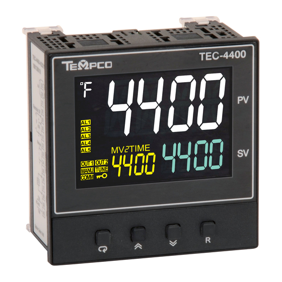
Introduction Introduction The new generation of Tempco PID microprocessor-based Fuzzy logic controller series incorporates two bright and easy to read LCD Displays which indicate Process Value (PV) and Set point (SP). The Fuzzy Logic technology incorporated on these series controllers enables a process to reach a predetermined set point in the shortest time with minimum of overshoot during start up (Power ON) or external load disturbances (example: an oven door being opened). -
Page 6: Features
TEC-7400 TEC-4400 TEC-6400 Power Supply 90 to 250VAC, 47 to63Hz , 20 to 28 VAC,47-63Hz / 11 to 40 VDC TEC-2400/TEC-6400: 8VA, 4W Maximum., TEC-9400: 10VA, 5W Maximum., TEC-7400/TEC-8400/TEC-8450/TEC-4400: 12VA,6W Power Consumption Maximum Signal Input Type Thermocouple(J,K,T,E,B,R,S,N,L,U,P,C,D), RTD(PT100(DIN), PT100(JIS)), Current(mA),Voltage(Volts) - Page 7 Specification TEC-2400 TEC-9400 TEC-8400 TEC-8450 TEC-7400 TEC-4400 TEC-6400 Sensor open for Thermocouple, RTD and mV inputs, Sensor short for RTD input , Sensor Break Detection Below 1mA for 4-20mA input, Below 0.25VDC for 1 - 5VDC input, Not available for other inputs.
- Page 8 Specification TEC-2400 TEC-9400 TEC-8400 TEC-8450 TEC-7400 TEC-4400 TEC-6400 Load Resistance 0 to 500Ω for current output , 10KΩ minimum for Voltage Output Output Regulation 0.01% for full load change Output Setting Time 0.1Second (stable to 99.9%) Isolation Breakdown 1000VAC min Integral Linearity Error ±0.005% of span...
-
Page 9: Keys And Displays
Specification TEC-2400 TEC-9400 TEC-8400 TEC-8450 TEC-7400 TEC-4400 TEC-6400 Safety UL61010-1, CSA 22.2 No.61010-1-12, EN61010-1 ( IEC1010-1 ) Protective Class IP66 for Panel (In process), IP20 for terminals and housing. All indoor use. EN61326 Keys and Displays KEYPAD OPERATION SCROLL KEY: This key is used to scroll through a menu to select a parameter to be viewed or adjusted. -
Page 10: Menu Flowchart
Menu Flowchart The Menu has been divided in to 5 groups. They are as follows: User Menu Setup Menu Manual Mode Menu Auto-Tuning Mode Menu Calibration Mode Menu (not recommended, calibration section has been removed) Manual Mode Auto-Tuning Mode Calibration Mode Setup User Menu Menu... -
Page 11: Setup Menu
1.5.2 Setup Menu The setup menu has been categorized in to eight categories. They are listed below. Basic Menu Output Menu Alarm Menu Event Input Menu User Select Menu Communication Menu Current Transformer Input Menu Profile Menu 1.5.2.1 Basic Menu (bASE) key to get bASE in the lower display, then use the key to enter to basic menu parameters. -
Page 12: Output Menu (Out)
1.5.2.2 Output Menu (oUT) key to get oUT in the lower display, then use the key to scroll through output menu parameters. OUT1 O1TY O1FT O1HY CYC1 OFST OUT2 O2TY O2FT CYC2 PL1L PL1H PL2L PL2H 1.5.2.3 Event Input Menu (EI) key to get EI in the lower display, then use the key to scroll through event input menu parameters. -
Page 13: Alarm Menu (Alrm)
1.5.2.4 Alarm Menu (ALRM) key to get ALRM in the lower display, then use the key to scroll through alarm menu parameters. ALRM A1FN A1MD A1HY A1FT A1SP A1DV A1DL A2OT A2FN A2MD A2HY A2FT A2SP A2DV A2DL A3OT A3FN A3MD A3HY A3FT... -
Page 14: User Select Menu (Sel)
1.5.2.5 User Select Menu (SEL) key to get SEL in the lower display, then use the key to scroll through the “select” user menu parameters. SEL1 SEL2 SEL3 SEL4 SEL5 SEL6 SEL7 SEL8 1.5.2.6 Communication Menu (CoMM) key to get CoMM in the lower display, then use the key to scroll through the communication menu parameters. -
Page 15: Current Transformer Input Menu (Ct)
1.5.2.7 Current Transformer Input Menu (Ct) key to get Ct in the lower display then, use the key to scroll through the Current transformer (CT) input menu parameters. HBEN HBHY HB1T HB2T HSEN HSHY HS1T HS2T Page 15 of 44... -
Page 16: Profile Menu (Prof)
1.5.2.8 Profile Menu (PRoF) key to get PRoF in the lower display, then use the key to scroll through the Profile menu parameters. PRoF PROF TSP7 RMPU RPT7 STAR SKT7 TSP8 RPT8 HBLO SKT8 HBHI TSP9 RPT9 CYCL SKT9 CYCR TSPA STEP RPTA... -
Page 17: Manual Mode Menu
1.5.3 Manual Mode Menu HANd 5 Sec FILE Press key 5 Sec To execute the selected default program 1.5.4 Auto-Tuning Mode Press and hold key 5 seconds to activate Auto-Tuning Mode Note: § Using Manual, Auto-Tuning, Calibration modes will break the control loop and change some of the previous setting data. -
Page 18: Installation And Wiring
Installation and Wiring Sometimes dangerous voltages capable of causing death are present in this instrument. Before beginning installation or any troubleshooting procedures, power to the equipment must be switched off and isolated. Units suspected of being faulty must be disconnected and removed to a properly equipped workshop for testing and repair. -
Page 19: Mounting
The tightening torque on the Screw terminals should not exceed 1 N-m (8.9 Lb-in or 10.2 Kg F-cm). Except Thermocouple Wiring, all other wires used are to be standard copper conductors with the maximum Gauge not exceeding 18AWG. 2.3.1 TEC-2400 Terminal Connection Page 19 of 44... -
Page 20: Tec-9400 Terminal Connection
2.3.2 TEC-9400 Terminal Connection 2.3.3 TEC-8400 & TEC-4400 Terminal Connection Page 20 of 44... -
Page 21: Tec-8450 Terminal Connection
2.3.4 TEC-8450 Terminal Connection 2.3.5 TEC-7400 Terminal Connection Page 21 of 44... -
Page 22: Tec-6400 Terminal Connection
2.3.6 TEC-6400 Terminal Connection Wiring Example: Contactor Page 22 of 44... -
Page 23: Wiring Example: Solid State Relay
Wiring Example: Solid State Relay Programming Press and hold the key for 5 seconds, then release to enter the setup menu. Press and release the key to select the desired parameter. The upper display indicates the parameter symbol, and the lower display indicates the value of the selected parameter. User Security There are two parameters, PASS (password) and CODE (security code), which will control the security function. -
Page 24: Control Output
Formula: PV = INLO + (INHI-INLO) ((S – SL)/ (SH-SL)) Example: A 4 -20mA current loop pressure transducer with range of 0-15 kg/cm is connected to the input. The following parameters should be set as follows: INPT = 4–20, INLO = 0.00, INHI = 15.00, DP = 2-DP The user may select a different value for DP to alter the resolution. -
Page 25: Heat Only P Or Pd Control
ON-OFF control may cause excessive process oscillations even if the hysteresis is set to the smallest value. If ON-OFF control is set (i.e. PB = 0), TI, TD, CYC1, OFST, CYC2, CPB, DB will no longer be applicable and will be hidden. Auto-Tuning and Bumpless transfer will also be unavailable. 3.3.2 Heat only P or PD Control Select REVR for OUT1, set TI = 0, OFST is used to adjust the control offset (manual reset).If... -
Page 26: Other Setup Required
3.3.5 Other Setup Required - O1TY, CYC1, O2TY, CYC2, O1FT, O2FT O1TY & O2TY are set in accordance with the type of outputs (OUT1 & OUT2) installed. - CYC1 & CYC2 are set according to the output 1 type (O1TY) & output 2 type (O2TY). Generally, if “SSRD”... -
Page 27: Soft-Start
Output 2 Deviation High Alarm Output 2 Process Low Alarm Soft-Start The controller has soft start function to limit the control output of OUT1 and OUT2 for a programmable time (SFT) or up to a programmed threshold value (SFTH). Once the time/temperature threshold has been reached, the soft start function will terminate and normal PID control begins. -
Page 28: Alarm
Alarm The controller has up to four alarm outputs depending on the controller model. There are 11 types of alarm functions and one dwell timer that can be selected. There are 4 kinds of alarm modes (A1MD, A2MD, A3MD, and A4MD) available for each alarm function (A1FN, A2FN, A3FN, and A4FN). In addition to the alarm output, output 2 can also be configured as an alarm. -
Page 29: Alarm Modes
In the above description, A1SP and A1HY denote the Alarm1 Set point and Alarm1 Hysteresis. The respective Set point and Hysteresis parameters need to be set for other Alarm outputs. Heater break detection is enabled by setting A1FN to HBEN. A Heater break alarm (H.bK) alerts the user when the current measured by CT1 in CT1R is lower than HB1T-HBHY, or CT2 in CT2R is lower than HB2T-HBHY. -
Page 30: Latching / Holding Alarm: Almd = Lt.ho
If the user needs a friendlier menu operation to suit their application, most conventional controllers do not offer a solution. Tempco digital controllers have the flexibility for the user to select those parameters which are most often used, and to put these parameters in an easy access USER menu. -
Page 31: Ramp
Ramp The ramping function is performed during power up as well as any time the set point is changed. Choose MINR (minutes) or HRR (hours) for the “RAMP” setting, and the controller will perform the ramping function. The ramp rate is programmed by adjusting the “RR” setting. The ramping function is disabled as soon as Failure mode, Manual control mode, Auto-Tuning mode, or Calibration mode occur. -
Page 32: User Calibration
User Calibration Each unit is calibrated in the factory before shipment. The user can still modify the calibration in the field. The basic calibration of the controller is highly stable and set for life. User calibration allows the user to offset the permanent factory calibration in order to: v Calibrate the controller to meet a user reference standard. -
Page 33: Failure Transfer
3.11 Failure Transfer The controller will enter failure mode if one of the following conditions occurs. 1. An “SBER” error occurs due to an input sensor break, an input current below 1mA for 4-20mA, or an input voltage below 0.25V for 1-5V. 2. -
Page 34: Auto-Tuning Operation Steps
3.12.1 Auto-Tuning Operation Steps 1. The system is operational under “real world” conditions. 2. Do not use a zero value for PB or TI; otherwise, the Auto-Tuning program will be disabled. The “LOCK” parameter should be set to NONE. 3. Set the set point to a normal operating value or a lower value if overshooting beyond the normal process value will cause damage. -
Page 35: Manual Tuning
3.13 Manual Tuning In certain applications, using Auto-Tuning to tune a process may be inadequate. If this is the case, the user can try manual tuning. The following guidelines can be applied for further adjustment of PID values. ADJUSTMENT SEQUENCE SYMPTOM SOLUTION Slow Response... -
Page 36: Manual Control
3.14 Manual Control To enable manual control, ensure the LOCK parameter is set to NONE. Press and hold for 6.2 seconds or until (Hand Control) appears on the display, then let go. Press and hold for an additional 5 seconds or until the MANU indicator begins to flash. The lower display will show Indicates the output control variable for output 1, and indicates the control variable for output 2. -
Page 37: Retransmission
3.16 Retransmission The controller can output (retransmit) PV or SP via its retransmission terminals RE+ and RE- provided that the retransmission option is ordered. The correct signal type should be selected for option board to meet the retransmission option installed. RELO and REHI are adjusted to specify the low scale and high scale values of retransmission. -
Page 38: Event Input
3.18 Event Input There are up to 6 Event Inputs that are available in this series of controllers depending on the size of the controller. Refer to section 2.8 for wiring an event input. The Event input accepts a digital (on/off) type signal. Types of signals that can be used to switch the event input as below. -
Page 39: Remote Set Point
LOCK: All parameters are locked and unable to be changed. AU.MA: Switch between Auto-Tuning and manual tuning control mode. F.tra: Switch to Failure Transfer Mode AL.oN: If Alarm 2 or Alarm 3 is set to “E1.c.o” or “E2.c.o” then EI1 or EI2 will activate Alarm Output Alarm 2 or Alarm 3. -
Page 40: Run
3.20.2 RUN Select the profile run mode. There are 5 modes available in the controller. 1. StAR: Start to run profile 2. CoNt: Continue run profile 3. PV: Continue run profile from current PV 4. Hold: Hold profile 5. SToP: Stop profile 3.20.2.1 StAR The Profile starts to run from the first segment in the selected profile. -
Page 41: Cont
3.20.6.1 CONT If CONT is selected, then when power is restored the profile continues from where it was interrupted when power was lost. The parameters such as set point value (SV), time remaining (DTMR) and cycle remaining (CYCR) will be restored to their power-down values. For applications that need to bring the process value to the set point value as soon as possible, this is the best choice. -
Page 42: Cyc
If the error from the set point exceeds the set holdback high band (HBHI) or lags behind the set holdback low band (HBLO), then the holdback function will automatically freeze the profile at its current point and the holdback timer begins to count. When the value of holdback timer exceeds the value of holdback wait time (HBT), Holdback indicator HdbK will flash and an error code HBER will be displayed. -
Page 43: Factory Default Settings
Factory Default Settings The controller parameters can be loaded with default values listed in the parameter description table. In certain situation it is desirable to retain these values after the parameters values has been changed. The below procedure to be followed to reload the default values. 1. - Page 44 æ The Electric Heating Element, Temperature Controls and Temperature Sensors Handbook REQUEST YOUR FREE 960 PAGE COPY TODAY! Call (800-323-6859) or E-mail (info@tempco.com) Specify Print Edition, CD-ROM or Both " ËUgtxk pi "K pf wuv t{ "Uk peg"3; 94È" Experience the Advantages of our Diverse and Innovative Products...