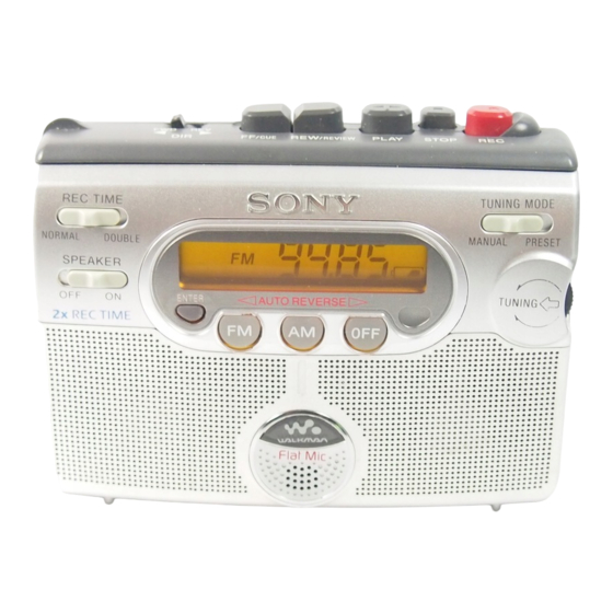
Sony WM-GX400 Service Manual
Radio cassette-corder
Hide thumbs
Also See for WM-GX400:
- Operating instructions (2 pages) ,
- Operating instructions (2 pages)
Table of Contents
Advertisement
QQ
3 7 63 1515 0
SERVICE MANUAL
Ver 1.0 2001.03
TE
L 13942296513
Frequency range
Area*
AEP, E, Chineses model
US, Canadian model
Tourist model
* E: European and other countries, U: Canada, and Central and
South America, J: Japan.
Frequency response
Input
Output
Power requirements
Dimensions (w/h/d)
Mass
Supplied accessories
Design and specifications are subject to change without notice.
www
.
Sony Corporation
9-873-087-11
2001C0200-1
Audio Entertainment Group
© 2001.3
General Engineering Dept.
http://www.xiaoyu163.com
FM (MHz)
AM (kHz)
87.5 - 108
531 - 1 602
87.5 - 108
530 - 1 710
76 - 90
531 - 1 710
Playback: 40 - 15,000 Hz
Recording: 100 - 8,000 Hz
Microphone (MIC) jack
Headphones (i) jack
Load impedance 8 - 300 ohms
3 V DC batteries R6 (size AA) × 2
External DC 3V power sources
Approx. 112.5 × 87.0 × 39.0 mm
× 3
× 1
1
1
9
(14
/
/
/
inches), excl.
2
2
16
projecting parts and controls
Approx. 190 g (6.8oz) (main unit only)
Stereo headphones or earphones (1)
Stereo microphone (1)
Sony dry battery R6P(SR) (2) ("Sony
World Model" only)
x
ao
y
i
http://www.xiaoyu163.com
WM-GX400
8
Model Name Using Similar Mechanism
Tape Transport Mechanism Type
SPECIFICATIONS
Q Q
3
6 7
1 3
Battery life (Approx. hours)
(using headphones/earphones)
playback
radio
mic recording
radio recording
(using the speakers)
playback
radio
radio recording
* Measured value by the standard of EIAJ (Electronic Industries
Association of Japan) (using a Sony HF series cassette tape).
** When using Sony LR6 (SG) "STAMINA" alkaline dry
batteries (produced in Japan).
Note
• The battery life may be shorter depending on the operating
condition, the surrounding temperature and battery type.
RADIO CASSETTE-CORDER
u163
.
2 9
9 4
2 8
Canadian Model
AEP Model
Chinese Model
Tourist Model
1 5
0 5
8
2 9
9 4
Sony alkaline LR6 (SG)** Sony R6P (SR)
24
48
20
12
13
23
8.5
m
co
9 9
E Model
NEW
MT-WMGX400-175
2 8
9 9
(EIAJ*)
6
15
4.5
3
3
6
1.5
Advertisement
Table of Contents

Related Manuals for Sony WM-GX400


Summary of Contents for Sony WM-GX400
-
Page 1: Specifications
* Measured value by the standard of EIAJ (Electronic Industries 3 V DC batteries R6 (size AA) × 2 Power requirements Association of Japan) (using a Sony HF series cassette tape). External DC 3V power sources ** When using Sony LR6 (SG) “STAMINA” alkaline dry Approx. -
Page 2: Table Of Contents
WM-GX400 TABLE OF CONTENTS 3 7 63 1515 0 Flexible Circuit Board Repairing Specifications ................1 • Keep the temperature of the soldering iron around 270°C during repairing. 1. GENERAL • Do not touch the soldering iron on the same conductor of the Location of Parts and Controls .......... -
Page 3: Disassembly
WM-GX400 SECTION 2 3 7 63 1515 0 DISASSEMBLY • The equipment can be removed using the following procedure. HRPE301 (REC/PB/ERASE head), Cabinet (Front) Main board Mechanism deck M601 (CAPSTAN/REEL motor), Belt (AR) Cabinet (Rear) Lid, cassette ASSY Display board Note : Follow the disassembly procedure in the numerical order given. -
Page 4: Main Board
WM-GX400 3 7 63 1515 0 2-2. MAIN BOARD Cabinet (front) 2 Flexible board (9 core) (CN303) White Black Orange Main board 3 Screw (M1.4) 3 Screw (M1.4) 1 Remove soldering (four places) L 13942296513 2-3. MECHANISM DECK 1 Screws (IB LOCK) -
Page 5: Hrpe301 (Rec/Pb/Erase Head), M601 (Capstan/Reel Motor), Belt (Ar)
WM-GX400 3 7 63 1515 0 2-4. HRPE301 (REC/PB/ERASE HEAD), M601 (CAPSTAN/REEL MOTOR), BELT (AR) Attaching belt (AR) 3 Belt (AR) 4 Screws (M1.4) 5 M601 (CAPSTAN/REEL motor) 1 Screws (M1.4) 2 HRPE301 (REC/PB/ERASE head) L 13942296513 2-5. DISPLAY BOARD... -
Page 6: Adjustments
WM-GX400 SECTION 3 ADJUSTMENTS 3 7 63 1515 0 3-1. MECHANICAL ADJUSTMENTS 3-2. ELECTRICAL ADJUSTMENTS PRECAUTION Note: 1. Clean the following parts with a denatured alcohol-moistened 1. Supplied voltage: 3 V (DC) swab : 2. Switch and control position... -
Page 7: Diagrams
WM-GX400 SECTION 4 DIAGRAMS 3 7 6 3 1 5 1 5 0 FM VCO Adjustment 4-1. EXPLANATION OF IC TERMINALS 0 dB = 1 µV TUNER SECTION Procedure: IC701 (SYSTEM CONTROL/LCD DRIVE) LC72349W-9A27 AM Section [MAIN BOARD] (SIDE B) Pin No. -
Page 8: Block Diagrams -Tape Section
WM-GX400 3 7 6 3 1 5 1 5 0 4-2. BLOCK DIAGRAMS – TAPE SECTION – [MAIN BOARD] (1/2) MIC301 Flat Mic IC302 (1/2) [DISPLAY BOARD] (1/3) REC/PB AMP MIC AMP J302 INPUT (L) IC302 PB PRE R-CH... -
Page 9: Block Diagrams -Tuner Section
WM-GX400 3 7 6 3 1 5 1 5 0 4-3. BLOCK DIAGRAMS – TUNER SECTION – MAIN BOARD (2/2) FM VCO MAIN BOARD (2/2) FM/AM/TV IC101 IC302 AM IF (L-CH) (2/2) FRONT-END, IC201 IF, DET, FM MPX PRE AMP... -
Page 10: Printed Wiring Board -Main Section (Side A)
WM-GX400 3 7 6 3 1 5 1 5 0 4-4. PRINTED WIRING BOARD – MAIN SECTION (SIDE A) – MAIN BOARD (SIDE A) Semiconductor Location Ref. No. Location CND,5E D402 C186 D403 C410 EXCEPT CND,5E Q307 Q308 FB303... -
Page 11: Printed Wiring Board -Main Section (Side B)
WM-GX400 3 7 6 3 1 5 1 5 0 4-5. PRINTED WIRING BOARD – MAIN SECTION (SIDE B) – DRY BATTERY DISPLAY BOARD DISPLAY BOARD SIZE "AA" CN701 CN702 (IEC DESIGNATION LR6) 2PCS, 3V MAIN BOARD (SIDE B) -
Page 12: Schematic Diagram -Main Section (1/2)
WM-GX400 3 7 6 3 1 5 1 5 0 4-6. SCHEMATIC DIAGRAM – MAIN SECTION (1/2) – Refer to page 17 for Notes. Refer to page 17 for Waveforms. Refer to page 18 for IC Block Diagram. 1 3 9 4 2 2 9 6 5 1 3... -
Page 13: Schematic Diagram -Main Section (2/2)
WM-GX400 3 7 6 3 1 5 1 5 0 4-7. SCHEMATIC DIAGRAM – MAIN SECTION (2/2) – Refer to page 17 for Notes. Refer to page 17 for Waveforms. Refer to page 19 for IC Block Diagram. 1 3 9 4 2 2 9 6 5 1 3... -
Page 14: Printed Wiring Board -Display Section (Side A)
WM-GX400 3 7 6 3 1 5 1 5 0 4-8. PRINTED WIRING BOARD – DISPLAY SECTION (SIDE A) – DISPLAY BOARD (SIDE A) S708 S710 S709 S712 ENTER ND701 S701 LIQUID CRYSTAL TUNING 1 3 9 4 2 2 9 6 5 1 3... -
Page 15: Printed Wiring Board -Display Section (Side B)
WM-GX400 3 7 6 3 1 5 1 5 0 4-9. PRINTED WIRING BOARD – DISPLAY SECTION (SIDE B) – DISPLAY BOARD (SIDE B) MAIN BOARD CN301 SP201 SP101 MAIN BOARD SPEAKER SPEAKER CN302 R-CH L-CH MIC301 Flat Mic... -
Page 16: Schematic Diagram -Display Section
WM-GX400 3 7 6 3 1 5 1 5 0 4-10. SCHEMATIC DIAGRAM – DISPLAY SECTION – Refer to page 17 for Notes. Refer to page 17 for Waveforms. 1 3 9 4 2 2 9 6 5 1 3... - Page 17 WM-GX400 3 7 63 1515 0 Common Note on Schematic Diagram: Waveforms • All capacitors are in µF unless otherwise noted. pF: µµF 50 WV or less are not indicated except for electrolytics – MAIN SECTION (1/2) – and tantalums.
- Page 18 WM-GX400 3 7 63 1515 0 • IC Block Diagrams IC1 CXA1960Q 22 21 MPRM AM RF FM RF TVRO TV RF REGV V12M OL DET 1.25V FM/TV OSC MUTE FM LMT FTLO MUTE 150kHz FM DET FM/TV AAGC FMBF 1.25V...
- Page 19 WM-GX400 3 7 63 1515 0 IC301 LB1979LV-TLM SPEED CONTROL STARTING OSCILLATING REFERENCE VOLTAGE DETECT CIRCUIT WAVEFORM DETECT COMMUTATION STARTING LOGIC SPEED CURRENT DETECT DETECT POWER SOFT SWITCH SUPPLY BIAS REFERENCE VOLTAGE PRE DRIVER CONTROL EACH BLOCKS BLOCKS L 13942296513 IC101, 201 NJM2073M A.OUT...
-
Page 20: Exploded Views
WM-GX400 SECTION 5 EXPLODED VIEWS 3 7 63 1515 0 NOTE : • -XX, -X mean standardized parts, so they • Abbreviation may have some difference from the original : Canadian one. : French • Items marked “ * ”are not stocked since they : Saudi Arabia are seldom required for routine service. -
Page 21: Cassette Lid Section
WM-GX400 3 7 63 1515 0 5-2. CASSETTE LID SECTION SP201 SP101 MIC301 L 13942296513 Ref. No. Part No. Description Remark Ref. No. Part No. Description Remark 3-318-203-63 SCREW (B1.7), TAPPING 3-034-792-01 SCREW, TAPPING (B2.0) 3-318-203-71 SCREW (B1.7X5), TAPPING... -
Page 22: Mechanism Section-1 (Mt-Wmgx400-175)
WM-GX400 3 7 63 1515 0 5-3. MECHANISM SECTION-1 (MT-WMGX400-175) A (Included in No.151) supplied supplied HRPE301 supplied L 13942296513 M601 Ref. No. Part No. Description Remark Ref. No. Part No. Description Remark 3-704-197-01 SCREW (M1.4), SPECIAL HEAD 3-042-480-01 SCREW (M1.4) -
Page 23: Mechanism Section-2 (Mt-Wmgx400-175)
WM-GX400 3 7 63 1515 0 5-4. MECHANISM SECTION-2 (MT-WMGX400-175) L 13942296513 (Including Ref. No. Part No. Description Remark Ref. No. Part No. Description Remark X-3379-878-1 CHASSIS ASSY 3-225-393-01 LEVER (SHUT/OFF) 3-225-385-01 GEAR (B) 3-225-448-01 SPRING (SHUT/OFF), TORSION 3-229-063-01 SPRING (UD) (R) -
Page 24: Electrical Parts List
WM-GX400 SECTION 6 MAIN ELECTRICAL PARTS LIST 3 7 63 1515 0 NOTE : • Abbreviation • Due to standardization, replacements in the • SEMICONDUCTORS In each case, u : µ , for example : : Canadian parts list may be different from the parts uA.. - Page 25 WM-GX400 MAIN 3 7 63 1515 0 Ref. No. Part No. Description Remark Ref. No. Part No. Description Remark C277 1-104-847-11 TANTAL. CHIP 22uF 8-719-076-71 DIODE KV1471ETR C278 1-162-970-11 CERAMIC CHIP 0.01uF 8-719-076-71 DIODE KV1471ETR C279 1-115-467-11 CERAMIC CHIP 0.22uF...
- Page 26 WM-GX400 MAIN 3 7 63 1515 0 Ref. No. Part No. Description Remark Ref. No. Part No. Description Remark Q374 8-729-230-63 TRANSISTOR 2SC4116-YG R179 1-216-825-11 METAL CHIP 2.2K 1/16W (FR) Q401 8-729-423-52 TRANSISTOR 2SC3931-C R179 1-216-849-11 METAL CHIP 220K...
- Page 27 WM-GX400 MAIN DISPLAY 3 7 63 1515 0 Ref. No. Part No. Description Remark Ref. No. Part No. Description Remark R343 1-216-829-11 METAL CHIP 4.7K 1/16W <TRANSFORMER> R344 1-216-864-91 SHORT R352 1-216-821-11 METAL CHIP 1/16W T331 1-433-286-23 TRANSFORMER, BIAS OSCILLATION...
- Page 28 WM-GX400 DISPLAY 3 7 63 1515 0 Ref. No. Part No. Description Remark Ref. No. Part No. Description Remark R702 1-216-833-11 METAL CHIP 1/16W <VIBRATOR> R703 1-216-833-11 METAL CHIP 1/16W R704 1-216-833-11 METAL CHIP 1/16W X701 1-760-130-11 VIBRATOR, CRYSTAL (75kHz)
- Page 29 WM-GX400 3 7 63 1515 0 L 13942296513 u163 http://www.xiaoyu163.com...
- Page 30 WM-GX400 3 7 63 1515 0 REVISION HISTORY Clicking the version allows you to jump to the revised page. Also, clicking the version at the upper right on the revised page allows you to jump to the next revised page.