Table of Contents
Advertisement
Quick Links
Advertisement
Table of Contents

Related Manuals for KTM 1290 Super Duke GT 2018


Summary of Contents for KTM 1290 Super Duke GT 2018
- Page 1 OWNER'S MANUAL 2018 1290 Super Duke GT Art. no. 3213759en...
- Page 3 DEAR KTM CUSTOMER Congratulations on your decision to purchase a KTM motorcycle. You are now the owner of a state-of-the-art DEAR KTM CUSTOMER sports motorcycle that will give you enormous pleasure if you service and maintain it properly. We hope you enjoy your new ride! Enter the serial numbers of your vehicle below.
- Page 4 Reproduction, even in part, as well as copying of all kinds, is permitted only with the express written permission of the copyright owner. ISO 9001(12 100 6061) According to the international quality management standard ISO 9001, KTM uses quality assur- ance processes that lead to the maximum possible quality of the products. Issued by: TÜV Management Service KTM Sportmotorcycle GmbH Stallhofnerstraße 3...
-
Page 5: Table Of Contents
TABLE OF CONTENTS VIEW OF VEHICLE ........20 TABLE OF CONTENTS MEANS OF REPRESENTATION ...... 9 View of vehicle, front left (example) ... 20 Symbols used ........9 View of vehicle, rear right Formats used........10 (example)........22 SAFETY ADVICE.......... 11 SERIAL NUMBERS ........ - Page 6 TABLE OF CONTENTS 6.4.6 Horn button ........ 33 6.17 Side stand........52 Switches on the right side of the COMBINATION INSTRUMENT ..... 54 handlebar........34 Overview ......... 54 6.5.1 Combination switch, right ..... 34 Activation and test ......54 6.5.2 Emergency OFF switch ....
- Page 7 TABLE OF CONTENTS 7.10.14 menu overview......74 Checking the basic position of the shift lever........94 7.10.15 "Language" ........75 7.10.16 "Distance" ........76 8.10 Adjusting the basic position of the shift lever ........95 7.10.17 "Temp" ........76 8.11 Setting the shift lever stub....
- Page 8 TABLE OF CONTENTS 11 SERVICE SCHEDULE ........ 123 13.11 Removing the main silencer ..137 13.12 Installing the main silencer ..138 11.1 Additional information ....123 13.13 Checking the chain for dirt....140 11.2 Required work ....... 123 13.14 Cleaning the chain ......140 11.3 Recommended work .......
- Page 9 TABLE OF CONTENTS 14.7 Adding rear brake fluid ....170 16.11 Adjusting the cornering light range ..........211 14.8 Checking the brake linings of the rear brake........172 16.12 Activating/deactivating the ignition key ..........214 15 WHEELS, TIRES ........174 16.13 Diagnostics connector ....
- Page 10 TABLE OF CONTENTS 20.2 Checks and maintenance steps for 26 AUXILIARY SUBSTANCES ......277 winter operation......242 27 STANDARDS ..........279 21 STORAGE ..........244 28 INDEX OF SPECIAL TERMS ....... 280 21.1 Storage ......... 244 29 LIST OF ABBREVIATIONS......281 21.2 Preparing for use after storage..
-
Page 11: Means Of Representation 1
All work marked with this symbol requires specialist knowledge and technical understanding. In the interest of your own safety, have these jobs performed by an authorized KTM workshop! Your motorcycle will be optimally cared for there by specially trained experts using the auxiliary tools required. -
Page 12: Formats Used
1 MEANS OF REPRESENTATION Indicates a voltage measurement. Indicates a current measurement. Indicates the end of an activity, including potential rework. Formats used The typographical formats used in this document are explained below. Proprietary name Indicates a proprietary name. Name ®... -
Page 13: Safety Advice 2
SAFETY ADVICE 2 Use definition – intended use The vehicle is designed and constructed to withstand the usual demands of regular traffic and use on race courses. This vehicle is not suitable for offroad use. Info This vehicle is only authorized for operation on public roads in its homologated version. Misuse The vehicle must only be used as intended. -
Page 14: Degrees Of Risk And Symbols
2 SAFETY ADVICE Info Various information and warning labels are attached in prominent locations on the model described. Do not remove any information or warning labels. If they are missing, you or others may not recognize dangers and may therefore be injured. Degrees of risk and symbols Danger Indicates a danger that will immediately and invariably lead to fatal or serious permanent injury if the... -
Page 15: Tampering Warning
SAFETY ADVICE 2 Tampering warning Tampering with the noise control system is prohibited. Federal law prohibits the following acts or the causing thereof: 1 The removal or rendering inoperative by any person other than for purposes of maintenance, repair, or replace- ment, of any device or element of design incorporated into any new vehicle for the purpose of noise control prior to its sale or delivery to the ultimate purchaser or while it is in use, or 2 the use of the vehicle after such device or element of design has been removed or rendered inoperative by any... - Page 16 The vehicle should only be used by trained persons. An appropriate driver's license is needed to ride the vehicle on public roads. Have malfunctions that impair safety promptly eliminated by an authorized KTM workshop. Adhere to the information and warning labels on the vehicle.
-
Page 17: Protective Clothing
– Always wear protective clothing that is in good condition and meets the legal regulations. In the interest of your own safety, KTM recommends that you only operate the vehicle while wearing protective clothing. Work rules Special tools are necessary for certain tasks. -
Page 18: Environment
Because motorcycles are not subject to the EU regulations governing the disposal of used vehicles, there are no legal regulations that pertain to the disposal of an end-of-life motorcycle. Your authorized KTM dealer will be glad to advise you. -
Page 19: Important Notes 3
Manufacturer and implied warranty The work specified in the service schedule may only be performed in an authorized KTM workshop and must be recorded in both the Service & Warranty Booklet and in KTM Dealer.net, otherwise any warranty coverage will become void. -
Page 20: Service
Please follow the instructions in the text. Customer service Your authorized KTM dealer will be happy to answer any questions you may have on your vehicle and KTM. - Page 21 IMPORTANT NOTES 3 A list of authorized KTM dealers can be found on the KTM website. International KTM Website: http://www.ktm.com...
-
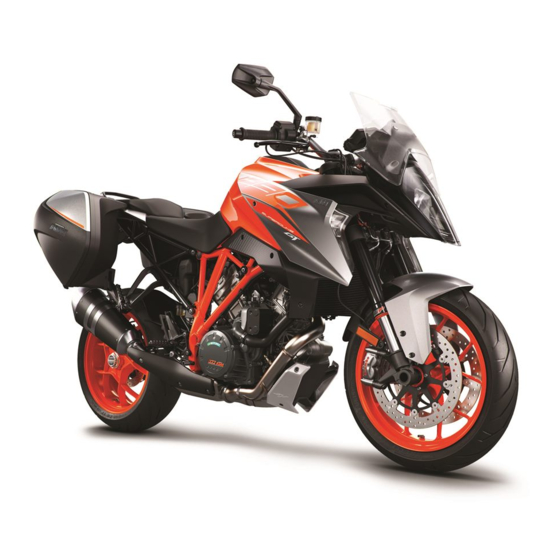
Page 22: View Of Vehicle
4 VIEW OF VEHICLE View of vehicle, front left (example) F01226-10... - Page 23 VIEW OF VEHICLE 4 Socket for electrical accessories ( p. 42) Clutch lever ( p. 28) Seat lock ( p. 48) Tool set ( p. 48) Grab handle ( p. 49) Passenger footrests ( p. 50) Rider footrests Shift lever ( p.
-
Page 24: View Of Vehicle, Rear Right (Example)
4 VIEW OF VEHICLE View of vehicle, rear right (example) F01227-10... - Page 25 VIEW OF VEHICLE 4 Ignition/steering lock ( p. 42) Filler cap Combination switch, left side ( p. 29) Electric starter button ( p. 40) Emergency OFF switch ( p. 35) Throttle grip ( p. 29) Hand brake lever ( p. 28) Cooling system compensating tank Foot brake lever ( p.
-
Page 26: Serial Numbers
5 SERIAL NUMBERS Chassis number The chassis number is stamped on the right side of the steer- ing head. The chassis number is also shown on the type label. 402324-10 Type label The type label is located on the steering head. 0 0 1 402302-10... -
Page 27: Key Number
SERIAL NUMBERS 5 Key number Key number Code number can be found on the KEYCODECARD. Info You need the key number to order a spare key. Keep the KEYCODECARD in a safe place. With the orange programming key, you can activate or deactivate the black ignition key. -
Page 28: Fork Part Number
5 SERIAL NUMBERS Fork part number The fork part number is stamped on the inside of the axle clamp. 402295-10 Shock absorber article number The shock absorber article number is printed on a sticker on the shock absorber case under the spring. H01165-10... -
Page 29: Steering Damper Article Number
SERIAL NUMBERS 5 Steering damper article number Steering damper item number is embossed on the underside of the steering damper. H01060-10... -
Page 30: Controls
6 CONTROLS Clutch lever Clutch lever is fitted on the handlebar on the left. The clutch is activated hydraulically and adjusts itself automati- cally. E00155-10 Hand brake lever The hand brake lever is fitted on the right side of the handle- bar. -
Page 31: Throttle Grip
CONTROLS 6 Throttle grip The throttle grip is fitted on the right side of the handlebar. E00156-11 Switches on the left side of the handlebar 6.4.1 Combination switch, left side The left combination switch is fitted on the left side of the handle- bar. -
Page 32: Light Switch
6 CONTROLS Overview of the left combination switch Light switch ( p. 30) Hazard warning flasher switch ( p. 31) Menu switch ( p. 32) Turn signal switch ( p. 32) Horn button ( p. 33) H01276-10 6.4.2 Light switch The light switch is fitted on the combination switch on the left. -
Page 33: Hazard Warning Flasher Switch
CONTROLS 6 6.4.3 Hazard warning flasher switch The hazard warning flasher switch is fitted on the combination switch on the left. The hazard warning flasher is used to indicate emergency situa- tions. Info The hazard warning flasher can be activated or deactivated while the ignition is switched on or up to 60 seconds after the ignition is switched off. -
Page 34: Menu Switch
6 CONTROLS 6.4.4 Menu switch The menu switch is fitted in the middle of the left combination switch. The menu buttons are used to control the matrix display on the combination instrument. Button is the UP button. Button is the DOWN button. Button is the SET button. -
Page 35: Horn Button
CONTROLS 6 To switch off the turn signal, press the turn signal switch towards the switch case. Info An automatic turn signal switch-off function (ATIR) is avail- able as a software feature. The ATIR function uses a time and distance counter. If the turn signal has been on for at least 10 seconds and 150 meters of riding distance, the turn signal is switched off. -
Page 36: Switches On The Right Side Of The Handlebar
6 CONTROLS Switches on the right side of the handlebar 6.5.1 Combination switch, right The right combination switch is fitted on the right side of the han- dlebar. Overview of the right combination switch Emergency OFF switch ( p. 35) Switch for the cruise control system ( p. -
Page 37: Emergency Off Switch
CONTROLS 6 6.5.2 Emergency OFF switch The emergency OFF switch is fitted on the right side of the handlebar. Possible states Emergency OFF switch off – In this position, the igni- tion circuit is interrupted, a running engine stops, and a non-running engine cannot be started. - Page 38 6 CONTROLS Info After activation of the cruise control system function, the throttle grip can be turned back to the home position. The selected speed will be maintained. To turn off the cruise control system function press the cruise con- trol system switch again.
- Page 39 CONTROLS 6 Warning Danger of accidents The cruise control system function is not suitable for all driving situations. The selected target speed will not be reached,if the engine power is not sufficient for a gradient. The selected target speed will be exceeded if the engine braking effect is not sufficient on a decline.
-
Page 40: Upper Button Of The Cruise Control System
6 CONTROLS 6.5.4 Upper button of the cruise control system Upper button of the cruise control system is fitted on the right side of the combination switch. Possible states • Upper button of the cruise control system in the home position. -
Page 41: Lower Button Of The Cruise Control System
CONTROLS 6 6.5.5 Lower button of the cruise control system Lower button of the cruise control system is fitted on the right side of the combination switch. Possible states • Lower button of the cruise control system in the home position. -
Page 42: Electric Starter Button
6 CONTROLS 6.5.6 Electric starter button The electric starter button is fitted on the right side of the handlebar. Possible states • Electric starter button in basic position. is pressed – In this position, the • Electric starter button electric starter is actuated. H01278-14 6.5.7 Locking the steering... -
Page 43: Unlocking The Steering
CONTROLS 6 – Park the vehicle. – Turn the handlebar all the way to the left. – Insert the key into the ignition/handlebar lock, press in, and turn to the left. Remove the key. Steering is no longer possible. 400732-01 6.5.8 Unlocking the steering –... -
Page 44: Socket For Electrical Accessories
6 CONTROLS 6.5.9 Socket for electrical accessories Socket for electrical accessories is mounted on the left side of the instrument support. It is connected to the permanent positive and is fuse-protected. Socket for electrical accessories Voltage 12 V Maximum cur- 10 A rent consump- tion... -
Page 45: Immobilizer
CONTROLS 6 Possible states Ignition off OFF – In this position, the ignition circuit is interrupted, a running engine stops, and a non- running engine will not start. The black ignition key can be removed. Ignition on ON – In this position, the ignition circuit is closed and the engine can be started. -
Page 46: Opening The Filler Cap
The black ignition keys are activated when delivered. Another two spare ignition keys (key number on the KEYCODECARD) can be ordered from an authorized KTM workshop; they need to be activated for use. Opening the filler cap Danger Fire hazard Fuel is highly flammable. - Page 47 CONTROLS 6 Warning Danger of poisoning Fuel is poisonous and a health hazard. – Avoid skin, eye and clothing contact with fuel. – Immediately consult a doctor if you swallow fuel. – Do not inhale fuel vapors. – In case of skin contact, rinse the affected area with plenty of water. –...
-
Page 48: Closing The Filler Cap
6 CONTROLS Note Danger of damage The ignition key may break if overloaded. Damaged ignition keys must be replaced. – Push down on the filler cap to take pressure off the igni- tion key. – Turn ignition key clockwise. – Fold open filler cap H01282-10 Closing the filler cap –... - Page 49 CONTROLS 6 – Press down the filler cap and turn back ignition key until the fuel tank lock locks. Warning Fire hazard Fuel is highly flammable, toxic and a health hazard. – Check the filler cap is locked correctly after clos- ing.
-
Page 50: Seat Lock
6 CONTROLS 6.10 Seat lock The seat lock is located on the left side of the vehicle. It can be unlocked using the ignition key. H01285-10 6.11 Tool set The storage compartment under the passenger seat contains tool S01097-10... -
Page 51: Grab Handle
CONTROLS 6 6.12 Grab handle The passenger can hold onto the grab handle during the trip. S01566-10 6.13 Case holders The case holders are located on each side of the passenger seat. A case system (optional) can be attached on the case holders. The case holders may not be loaded with more than the specified weight. -
Page 52: Passenger Footrests
6 CONTROLS Info Follow the instructions provided by the luggage manufac- turer. 6.14 Passenger footrests The passenger footrests can be folded up and down. Possible states Passenger footrests folded up – For operation without a pas- • senger. Passenger footrests folded down – For operation with a pas- •... -
Page 53: Shift Lever
CONTROLS 6 6.15 Shift lever The shift lever is fitted on the left side of the engine. 402299-10 The gear positions can be seen in the figure. The idle position is between the first and second gears. 402299-11... -
Page 54: Foot Brake Lever
6 CONTROLS 6.16 Foot brake lever Foot brake lever is located in front of the right footrest. The rear brake is engaged with the foot brake lever. 402301-10 6.17 Side stand Side stand is located on the left of the vehicle. The side stand is used for parking the motorcycle. - Page 55 CONTROLS 6 Side stand folded in – This position is mandatory when riding • the motorcycle. The safety starting system is inactive.
-
Page 56: Combination Instrument
7 COMBINATION INSTRUMENT Overview Matrix display ( p. 55) Tachometer Shift warning light ( p. 62) Segment display Indicator lamps ( p. 58) F01244-01 Activation and test Activation The combination instrument is activated when the ignition is switched on. Info The brightness of the displays is controlled by a brightness sensor in the combination instrument. -
Page 57: Matrix Display
COMBINATION INSTRUMENT 7 The welcome text and information on the next service ( p. 63) appear on the matrix display. Info If the battery was removed, the time and date must be set. Matrix display The matrix display is controlled using the menu switch ( p. -
Page 58: Segment Display
7 COMBINATION INSTRUMENT Segment display Fuel level display ( p. 57) Cruise control system symbol Time symbol Unit for the speedometer Gear display Speed "Drive Mod" ( p. 226) Target speed of the cruise control system or time L02904-10 Coolant temperature "Load"... -
Page 59: Fuel Level Display
COMBINATION INSTRUMENT 7 Fuel level display The fuel level display shows the filling level of the fuel tank. Info The fuel level is displayed with a slight delay to prevent the indicator from constantly moving while riding. The fuel level display is not updated while the side stand is folded out or the emergency off switch is switched off. -
Page 60: Indicator Lamps
7 COMBINATION INSTRUMENT Indicator lamps Possible states The high beam indicator lamp lights up blue – The high beam is switched on. The immobilizer indicator lamp lights up or flashes red – Status or error message for immobilizer/alarm system. The oil pressure warning lamp lights up red – Engine oil pressure is too low. - Page 61 COMBINATION INSTRUMENT 7 Malfunction indicator lamp lights up/flashes yellow – The engine electronics control unit has detected a fault. ABS indicator lamp lights up/flashes yellow – The ABS is not active. The ABS indicator lamp also lights up if an error is detected. TC indicator lamp lights up/flashes yellow –...
-
Page 62: Message On The Matrix Display
7 COMBINATION INSTRUMENT Message on the matrix display Possible states Engine malfunction – The engine electronics control unit has detected a fault. Visit an authorized KTM workshop. General message – General message on operating safety. Visit an authorized KTM workshop. - Page 63 Battery voltage – The battery voltage is too low. Recharge the battery with a suitable battery charger. Service – A service is due. Contact an authorized KTM workshop. Emergency OFF switch – The emergency OFF switch is off.
-
Page 64: Shift Warning Light
7 COMBINATION INSTRUMENT Shift warning light The shift warning light flashes or lights up when the transmission should be shifted. In the "Shift Light" menu, the engine speed for the shift warning light can be set. The shift warning light flashes at "RPM1" and lights up at "RPM2". -
Page 65: Service Display
COMBINATION INSTRUMENT 7 The shift warning 6,500 rpm light always lights up Service display After the ignition is switched on, the service display appears briefly. The service intervals depend on the distance traveled or the elapsed time. The event that occurs first applies. The exact service intervals can be found in the service schedule. -
Page 66: Matrix Display Menu
7 COMBINATION INSTRUMENT 7.10 Matrix display menu 7.10.1 "Favorites" – Press the UP or DOWN button until the "Favorites" menu appears on the matrix display. Pressing the SET button opens the menu. – Press the UP or DOWN button to select the menu item and acti- vate it with the SET button. -
Page 67: Trip 2
COMBINATION INSTRUMENT 7 "Trip Time 1" indicates the riding time based on "Trip 1" and starts running as soon as a speed signal comes in. "Fuel Range" indicates the possible range with the fuel reserve. Press and All entries in the "Trip 1" menu are cleared. hold the SET button for 3-5 seconds. -
Page 68: General Info
7 COMBINATION INSTRUMENT Press and All entries in the "Trip 2" menu are cleared. hold the SET button for 3-5 seconds. 7.10.4 "General Info" – Press the UP oder DOWN button until the "General Info" menu appears on the matrix display. "Air Temp"... -
Page 69: Tpms
COMBINATION INSTRUMENT 7 7.10.5 "TPMS" Condition • Model with TPMS. Warning Danger of accidents The tire pressure control system does not eliminate the necessity to check the tires before going on a ride. To avoid false alarms, the tire pressure values are evaluated over a period of several minutes. -
Page 70: Set Favorites
7 COMBINATION INSTRUMENT The "TPMS" menu displays the tire air pressure of the front and rear tires. "FW" indicates the tire air pressure at the front. "RW" indicates the tire air pressure at the rear. 7.10.6 "Set Favorites" Condition • The vehicle is stationary. -
Page 71: Settings
COMBINATION INSTRUMENT 7 7.10.7 "Settings" Condition • The vehicle is stationary. – Press the UP or DOWN button until the "Settings" menu appears on the matrix display. Pressing the SET button opens the menu. Settings for units or various values are made in the "Settings" menu. -
Page 72: Heating
7 COMBINATION INSTRUMENT 7.10.9 "Heating" – Press UP or DOWN button until the "Heating" menu appears on the matrix display. Pressing the SET button opens the menu. – Use the SET button to select a heating level or to switch off the heated grips. - Page 73 COMBINATION INSTRUMENT 7 – Press the UP or DOWN button until the "MTC/ABS" menu appears on the matrix display. In the "MTC/ABS" menu, "MTC" and "ABS" can be switched off. In "ABS Mode", you can select between "ROAD" and "SUP MOT". Info After the ignition is switched on, motorcycle traction con- trol and ABS are enabled again.
-
Page 74: Load
7 COMBINATION INSTRUMENT 7.10.11 "Load" Condition • The vehicle is stationary. • Engine is running. – Press the UP or DOWN button until the "Load" menu appears on the matrix display. Pressing the SET button opens the menu. – Press the UP or DOWN button to select a loading condition and activate it with the SET button. -
Page 75: Drive Mod
COMBINATION INSTRUMENT 7 7.10.13 "Drive Mod" – Press the UP or DOWN button until the "Drive Mod" menu appears on the matrix display. Press the SET button to open the menu. Info If the setting for "Drive Mod" is changed, the relevant setting for "Damping"... -
Page 76: Menu Overview
7 COMBINATION INSTRUMENT 7.10.14 menu overview F01246-01... -
Page 77: Language
COMBINATION INSTRUMENT 7 KTM start screen Menu buttons "Favorites" "Trip 1" "Trip 2" "General info" "TPMS" (only active if TPMS is available) "Set Favorites" "Settings" "Warning" (only active if there are messages) "Heating" "MTC/ABS" "Load" "Damping" "Drive Mod" 7.10.15 "Language"... -
Page 78: Distance
7 COMBINATION INSTRUMENT 7.10.16 "Distance" Condition • The vehicle is stationary. – Press the UP or DOWN button until the "Settings" menu appears on the matrix display. Pressing the SET button opens the menu. – Press the UP or DOWN button until "Distance" is highlighted in black on the matrix display. -
Page 79: Pressure
COMBINATION INSTRUMENT 7 7.10.18 "Pressure" Condition • The vehicle is stationary. – Press the UP or DOWN button until the "Settings" menu appears on the matrix display. Pressing the SET button opens the menu. – Press the UP or DOWN button until "Pressure" is highlighted in black on the matrix display. -
Page 80: Clock/Date
7 COMBINATION INSTRUMENT 7.10.20 "Clock/Date" Condition • The vehicle is stationary. – Press the UP or DOWN button until the "Settings" menu appears on the matrix display. Pressing the SET button opens the menu. – Press the UP or DOWN button until "Clock/Date" is highlighted in black on the matrix display. -
Page 81: Heat Grip
COMBINATION INSTRUMENT 7 – Press the UP or DOWN button to select the function. Use the SET button to set the engine speed for the shift warning light. When the engine speed reaches "RPM 1", the shift warning light flashes. When the engine speed reaches "RPM 2", the shift warning light lights up continuously. -
Page 82: Clighttest
7 COMBINATION INSTRUMENT 7.10.23 "cLightTest" Condition • The vehicle is stationary. – Press the UP or DOWN button until the "Settings" menu appears on the matrix display. Pressing the SET button opens the menu. – Press the UP or DOWN button until "cLightTest" is highlighted in black on the matrix display. -
Page 83: Drl
COMBINATION INSTRUMENT 7 7.10.24 "DRL" Condition • The vehicle is stationary. – Press the UP or DOWN button until the "Settings" menu appears on the matrix display. Pressing the SET button opens the menu. Warning Danger of accidents When visibility is poor, the day- time running light is not a substitute for the low beam. -
Page 84: Quick Shift
7 COMBINATION INSTRUMENT – Press the UP or DOWN button until "DRL" is highlighted in black on the matrix display. Pressing the SET button again switches the daytime running light on or off. Switch the daytime running light on or off. 7.10.25 "Quick Shift"... -
Page 85: Ergonomics 8
ERGONOMICS 8 Handlebar position On the upper triple clamp there are two holes at a distance of apart. 15 mm (0.59 in) Hole distance The handlebar supports can be turned through 180 °. The handlebar can be mounted in four different positions. In this way, the handlebar can be mounted in the most comfortable posi- tion for the rider. - Page 86 8 ERGONOMICS – Remove screws . Take off handlebar clamp . Take off the handlebar and place it to the rear. Info Cover the components to protect them against damage. Do not kink the cables and lines. – Remove screws .
- Page 87 ERGONOMICS 8 – Position the handlebar. Info Make sure the cables and wiring are positioned cor- rectly. – Position the handlebar clamp. Mount screws but do not tighten yet. Marking on the handlebar scale is aligned with the top S01102-12 edge of the handlebar clamp.
- Page 88 8 ERGONOMICS – Place on the vehicle and adjust both mirrors in a horizontal position. – Check minimum spacing between the mirror bar and wind- shield after the handlebar has been driven in fully. Guideline 9 mm (0.35 in) Minimum spacing between the mirror bar and windshield F01230-10...
-
Page 89: Adjusting The Steering Angle
ERGONOMICS 8 Adjusting the steering angle – Loosen nuts – Make sure that sufficient steering angle remains after finishing the work. Info Do not unscrew screws fully. The screw must be screwed in by at least five full turns. – Adjust the steering angle by turning adjusting screws left F01228-10... -
Page 90: Adjusting The Windshield
8 ERGONOMICS – Make sure that there is sufficient space between the controls and fuel tank when the handlebar has been driven in fully after completing the work. Adjusting the windshield Info Do not make any adjustments while riding. – Push the windshield in the direction of travel. - Page 91 ERGONOMICS 8 – To move the windshield to the desired position, push the wind- shield upward or downward. S01569-10 – Push the windshield into the locking mechanism against the direction of travel. The windshield is locked. S01568-10...
-
Page 92: Adjusting The Basic Position Of The Clutch Lever
8 ERGONOMICS Adjusting the basic position of the clutch lever – Push the clutch lever forward. – Adjust the basic position of the clutch lever to your hand size by turning adjusting screw Info Turn the adjusting screw clockwise to increase the distance between the clutch lever and the handlebar. -
Page 93: Adjusting The Basic Position Of The Hand Brake Lever
ERGONOMICS 8 Adjusting the basic position of the hand brake lever – Push the hand brake lever forward. – Adjust the basic position of the hand brake lever to your hand size by turning adjusting screw Info Turn the adjusting screw clockwise to increase the distance between the hand brake lever and the han- dlebar. -
Page 94: Adjusting The Basic Position Of The Foot Brake Lever
8 ERGONOMICS Adjusting the basic position of the foot brake lever – Loosen nut – Press the foot brake lever down to be able to turn push rod more easily. – Turn the push rod until the foot brake lever is in the desired position. -
Page 95: Setting The Step Plate Of The Foot Brake Lever
ERGONOMICS 8 Setting the step plate of the foot brake lever – Remove screw together with the step plate of the foot brake lever. – To adjust the length of the foot brake lever, position the step plate of the foot brake lever using screw in a drill hole Guideline Standard... -
Page 96: Checking The Basic Position Of The Shift Lever
8 ERGONOMICS Checking the basic position of the shift lever Info When driving, the shift lever must not touch the rider's boot when in the basic position. If the shift lever is permanently touching the boot, the transmission will be subject to excessive load; this can cause a malfunction of the quickshifter. -
Page 97: Adjusting The Basic Position Of The Shift Lever
ERGONOMICS 8 8.10 Adjusting the basic position of the shift lever – Loosen nut , holding the threaded rod Info has a left-handed thread. – Loosen nut , holding the threaded rod – Turn threaded rod to adjust the shift lever. Info S01570-10 The range of adjustment is limited. -
Page 98: Setting The Shift Lever Stub
8 ERGONOMICS 8.11 Setting the shift lever stub – Remove screw along with the shift lever stub. – Position the shift lever stub with the screw in one of the drilled holes depending on the desired lever length. Guideline Standard Middle hole –... -
Page 99: Preparing For Use 9
Make sure that only tires with a similar tire tread pattern are fitted to the front and rear wheel. Warning Danger of accidents Non-approved or non-recommended tires and wheels impact the handling character- istic. – Only use tires/wheels approved by KTM with the corresponding speed index. - Page 100 When using your vehicle, remember that others may feel disturbed by excessive noise. – Make sure that the pre-delivery inspection work has been carried out by an authorized KTM workshop. You receive a delivery certificate and the Service and Warranty Booklet at vehicle handover.
-
Page 101: Running In The Engine
PREPARING FOR USE 9 – Run the engine in. Running in the engine – During the running-in phase, do not exceed the specified engine speed. Guideline Maximum engine speed During the first: 1,000 km (620 mi) 6,500 rpm After the first: 1,000 km (620 mi) 10,500 rpm During the running-in phase, set the shift warning light to the specified engine speed. - Page 102 9 PREPARING FOR USE Warning Danger of accidents Improper mounting of cases or the tank rucksack impairs the handling characteris- tic. – Mount and secure cases and tank rucksack according to the manufacturer's instructions. Warning Danger of accidents Unstable handling characteristics at high speed. –...
- Page 103 PREPARING FOR USE 9 Warning Danger of accidents A high payload alters the handling characteristic and increases the stopping distance. – Adapt your speed to your payload. Warning Danger of accidents Pieces of luggage which have slipped impair the handling characteristic. – Check that your luggage is fixed properly at regular intervals.
-
Page 104: Riding Instructions
10 RIDING INSTRUCTIONS 10.1 Checks and maintenance measures when preparing for use Info Before every trip, check the condition of the vehicle and ensure that it is roadworthy. The vehicle must be in perfect technical condition when it is being operated. –... -
Page 105: Starting The Vehicle
RIDING INSTRUCTIONS 10 10.2 Starting the vehicle Danger Danger of poisoning Exhaust gases are toxic and inhaling them may result in unconsciousness and death. – Always make sure there is sufficient ventilation when running the engine. – Use an effective exhaust extraction system when starting or running the engine in an enclosed space. Caution Danger of accidents Electronic components and safety devices will be damaged if the battery is discharged or missing. - Page 106 10 RIDING INSTRUCTIONS – Press the emergency OFF switch to the position ON – Switch on the ignition by turning the black ignition key to the position ON After you switch on the ignition, you can hear the fuel pump working for about two seconds. The function check of the combination instrument is run at the same time.
-
Page 107: Starting Off
RIDING INSTRUCTIONS 10 Info Do not press the electric starter button until the combi- nation instrument function check is finished. When starting, DO NOT open the throttle. If you open the throttle during the starting procedure, fuel is not injected by the engine management system and the engine cannot start. -
Page 108: Start Off With Hhc (Option: Hill-Start Assist)
10 RIDING INSTRUCTIONS 10.4 Start off with HHC (Option: Hill-start assist) The HHC is an optional auxiliary function of the brake system. The HHC prevents accidental rolling back of the motorcycle on hills. The HHC recognizes stopping on hills and operates the rear brake. After releasing the brake lever, the brake force is maintained for a maximum of 5 seconds as long as the motorcycle is not moving forward. -
Page 109: Quickshifter
RIDING INSTRUCTIONS 10 10.5 Quickshifter When the quickshifter is activated, you can shift up under load without actuating the clutch. Because there is no need to close the throttle grip, uninterrupted gear shifts are possible. The quickshifter uses the shifter shaft position to check whether or not a shift should be initiated, and sends a corresponding signal to the engine control. -
Page 110: Shifting, Riding
10 RIDING INSTRUCTIONS 10.6 Shifting, riding Warning Danger of accidents Abrupt load alterations can cause the vehicle to get out of control. – Avoid abrupt load alterations and sudden braking actions. – Adapt your speed to the road conditions. Warning Danger of accidents If you change down at high engine speed, the rear wheel blocks and the engine races. - Page 111 RIDING INSTRUCTIONS 10 Warning Risk of injury The passenger may fall from the motorcycle if they conduct themselves incorrectly. – Ensure that the passenger sits correctly on the passenger seat, places his or her feet on the passenger foot rest and holds on to the rider or the grab handles. –...
- Page 112 10 RIDING INSTRUCTIONS Warning Danger of accidents Total weight and axle loads influence the handling characteristic. The overall weight consists of: motorcycle ready for operation and with a full tank, driver and passenger with protective clothing and helmet, and luggage. – Do not exceed the maximum permissible overall weight or the axle loads.
- Page 113 – Pull the clutch lever to shift down. Info If unusual noises occur while riding, stop immediately, switch off the engine and contact an authorized KTM workshop. – Shift into a higher gear when conditions allow (incline, road situation, etc.).
- Page 114 10 RIDING INSTRUCTIONS Info You can see the positions of the 6 forward gears in the figure. The idle position is between the first and sec- ond gears. First gear is used for starting off or for steep inclines. – If the quickshifter is enabled in the combination instrument, you can shift up under load without pulling the clutch lever.
- Page 115 Stop immedi- ately, taking care not to endanger yourself or other road users in the process, and switch off the engine. Contact an autho- rized KTM workshop. – If the malfunction indicator lamp lights up while riding, stop immediately taking care not to endanger yourself or other road users in the process.
-
Page 116: Msr (Option: Engine Braking Control)
10 RIDING INSTRUCTIONS Info Very important messages are stored in the "Warning" menu. – If the icy road symbol appears in the combination instru- ment, the roads may be icy. Adjust your speed to the road con- ditions. 10.7 MSR (Option: Engine braking control) The MSR is an optional auxiliary function of the engine control. -
Page 117: Applying The Brakes
Danger of accidents A spongy pressure point on the front or rear brake reduces braking efficiency. – Check the brake system and do not continue riding until the problem is eliminated. (Your authorized KTM workshop will be glad to help.) Warning Danger of accidents The brake system fails in the event of overheating. - Page 118 10 RIDING INSTRUCTIONS Warning Danger of accidents ABS may increase the stopping distance in certain situations. – Adjust application of the brakes to the respective riding situation and riding surface conditions. Warning Danger of accidents Excessively forceful application of the brakes blocks the wheels. The ABS effectiveness is only ensured if it is switched on.
-
Page 119: Stopping, Parking
RIDING INSTRUCTIONS 10 Warning Danger of accidents The rear wheel can lock due to the engine braking effect. – Pull in the clutch, if you perform emergency or full braking, or if you brake on a slippery ground. Warning Danger of accidents Banked or laterally sloping ground reduces the maximum possible delay. –... - Page 120 10 RIDING INSTRUCTIONS Warning Danger of burns Some vehicle components become very hot when the vehicle is operated. – Do not touch any parts such as the exhaust system, radiator, engine, shock absorber, or brake system before the vehicle parts have cooled down. –...
-
Page 121: Transporting
RIDING INSTRUCTIONS 10 Info If the engine is switched off with the emergency OFF switch and the ignition remains switched on at the ignition lock, power continues to flow to most power consumers. This discharges the battery. You should therefore always switch off the engine with the ignition lock – the emergency OFF switch is intended for emergencies only. -
Page 122: Refueling
10 RIDING INSTRUCTIONS – Switch off the engine. – Use tension belts or other suitable devices to secure the motorcycle against falling over or rolling away. 401475-01 10.11 Refueling Danger Fire hazard Fuel is highly flammable. The fuel in the fuel tank expands when warm and can escape if overfilled. –... - Page 123 In some countries and regions, the available fuel quality and cleanliness may not be sufficient. This will result in problems with the fuel system. – Refuel only with clean fuel that meets the specified standards. (Your authorized KTM workshop will be glad to help.) Warning Environmental hazard Improper handling of fuel is a danger to the environment.
- Page 124 10 RIDING INSTRUCTIONS – Switch off the engine. – Open the filler cap. ( p. 44) – Fill the fuel tank with fuel up to the lower edge of the filler neck. Total fuel tank 23 l Super unleaded capacity, approx. (6.1 US gal) (ROZ 95/RON 95/PON 91)
-
Page 125: Service Schedule 11
Different service intervals may apply in your country, depending on the local operating conditions. Individual service intervals and scopes may change in the course of technical developments. The most up-to-date service schedule can always be found on KTM Dealer.net. Your authorized KTM dealer will be happy to advise you. - Page 126 11 SERVICE SCHEDULE Every two years Every year every 30,000 km (18,600 mi) every 15,000 km (9,300 mi) after 1,000 km (620 mi) ● Change the front brake fluid. ● Change the rear brake fluid. ● Change the hydraulic clutch fluid. ○...
- Page 127 ○ ● ● ● ● Reset the service display using the KTM diagnostic tool. ○ ● ● ● ● Make the service entry in the KTM Dealer.net and in the Service and Warranty Booklet. ○ One-time interval ● Periodic interval...
-
Page 128: Recommended Work
11 SERVICE SCHEDULE 11.3 Recommended work Every four years Every year every 30,000 km (18,600 mi) every 15,000 km (9,300 mi) after 1,000 km (620 mi) ● Check the frame. ● Check the swingarm. ○ ● ● Check/clean the oil nozzle for clutch lubrication. ●... -
Page 129: Suspension Setting 12
SUSPENSION SETTING 12 12.1 Fork/shock absorber Semi-active suspension WP Semi‑active Suspension can be used to tune the suspension individually without the use of tools. Electronic suspension setting WP Semi‑active Suspension constantly regulates the damping behavior of the sus- pension taking into account various sensor data. As a result, the electronic damping valves are matched to the current driving situation and terrain characteristics as well as the settings made by the rider in the "Load"... -
Page 130: Damping
12 SUSPENSION SETTING Info For the setting to be accepted by the motorcycle, the motorcycle must be stationary and the engine must be running. The symbol of the last load status flashes until the new setting is adopted. 12.3 "Damping" Possible states SPORT –... -
Page 131: Service Work On The Chassis 13
SERVICE WORK ON THE CHASSIS 13 13.1 Raising the motorcycle with the rear lifting gear Note Danger of damage The parked vehicle can roll away or fall over. – Park the vehicle on a firm and level surface. – Insert the adapter in the rear lifting gear. Rear wheel work stand for single-sided swing arm (61329955000) –... -
Page 132: Lifting The Motorcycle With The Front Lifting Gear
13 SERVICE WORK ON THE CHASSIS – Secure the motorcycle against falling over. – Remove the rear wheel stand and lean the vehicle on side stand 402029-10 13.3 Lifting the motorcycle with the front lifting gear Note Danger of damage The parked vehicle can roll away or fall over. –... -
Page 133: Taking The Motorcycle Off The Front Lifting Gear
SERVICE WORK ON THE CHASSIS 13 Main work – Move the handlebar to the straight-ahead position. – Position front lifting gear with adapter. Mounting pin (69329965040) Front wheel work stand, large (69329965000) – Align the front lifting gear with the fork legs. Info 402345-01 Always raise the motorcycle at the rear first. -
Page 134: Removing The Passenger Seat
13 SERVICE WORK ON THE CHASSIS – Secure the motorcycle against falling over. – Remove the front lifting gear. 402777-01 13.5 Removing the passenger seat – Insert the ignition key in seat lock and turn it clockwise. – Raise front of the passenger seat, pull toward the fuel tank, and take off from above. -
Page 135: Mounting The Passenger Seat
SERVICE WORK ON THE CHASSIS 13 13.6 Mounting the passenger seat – Attach the hooks on the passenger seat to seat mounts – Lower the front of the passenger seat and push back. – Position locking pin in the lock housing and push the pas- senger seat down at the front. - Page 136 13 SERVICE WORK ON THE CHASSIS Main work – Press seat release in the direction of the arrow and lift the front rider's seat at the rear at the same time. – Detach the front of the front rider's seat and take it off. S01104-10...
-
Page 137: Mounting The Front Rider's Seat
SERVICE WORK ON THE CHASSIS 13 13.8 Mounting the front rider's seat Main work – Attach recesses on the front rider's seat to the fuel tank, push the front rider's seat forward. – Position locking pin in the lock housing and push down the front rider's seat at the rear. -
Page 138: Removing The Windshield
13 SERVICE WORK ON THE CHASSIS 13.9 Removing the windshield – Remove screws and windshield S01574-10 13.10 Installing the windshield – Position windshield – Mount and tighten screws Guideline Screw, windshield 3.5 Nm (2.58 lbf ft) S01574-11... -
Page 139: Removing The Main Silencer
SERVICE WORK ON THE CHASSIS 13 13.11 Removing the main silencer – Remove screw – Take off the exhaust clamp. H01297-10 – Remove screw Warning Risk of injury Moving parts of the exhaust valve con- stitute a risk of injury. – Do not touch the exhaust valve if the main silencer has been removed. -
Page 140: Installing The Main Silencer
13 SERVICE WORK ON THE CHASSIS – Remove seal ring R00007-10 13.12 Installing the main silencer Warning Risk of injury Moving parts of the exhaust valve con- stitute a risk of injury. – Do not touch the exhaust valve if the main silencer has been removed. - Page 141 SERVICE WORK ON THE CHASSIS 13 – Position the main silencer. – Mount screw but do not tighten yet. Guideline Remaining screws, 25 Nm (18.4 lbf ft) chassis R00006-10 – Position the exhaust clamp. – Mount and tighten screw Guideline Screw, exhaust 8 Nm (5.9 lbf ft) clamp on main...
-
Page 142: Checking The Chain For Dirt
13 SERVICE WORK ON THE CHASSIS 13.13 Checking the chain for dirt – Check the chain for coarse dirt accumulation. » If the chain is very dirty: – Clean the chain. ( p. 140) 400678-01 13.14 Cleaning the chain Warning Danger of accidents Oil or grease on the tires reduces the road grip. - Page 143 SERVICE WORK ON THE CHASSIS 13 Warning Environmental hazard Hazardous substances cause environmental damage. – Dispose of oils, grease, filters, fuel, cleaning agents, brake fluid, etc., correctly and in compliance with the applicable regulations. Info The service life of the chain depends largely on its maintenance. Regular cleaning increases the service life of the chain.
-
Page 144: Checking The Chain Tension
13 SERVICE WORK ON THE CHASSIS 13.15 Checking the chain tension Warning Danger of accidents Incorrect chain tension damages components and results in accidents. If the chain is tensioned too much, the chain, engine sprocket, rear sprocket, transmission and rear wheel bearings wear more quickly. Some components may break if overloaded. If the chain is too loose, the chain may fall off the engine sprocket or the rear sprocket. - Page 145 SERVICE WORK ON THE CHASSIS 13 The upper edge of the chain is located between markings » If the chain tension does not meet the specification: – Adjust the chain tension. ( p. 144) – Check locking caps for damage and firm seating. »...
-
Page 146: Adjusting The Chain Tension
13 SERVICE WORK ON THE CHASSIS 13.16 Adjusting the chain tension Warning Danger of accidents Incorrect chain tension damages components and results in accidents. If the chain is tensioned too much, the chain, engine sprocket, rear sprocket, transmission and rear wheel bearings wear more quickly. Some components may break if overloaded. If the chain is too loose, the chain may fall off the engine sprocket or the rear sprocket. -
Page 147: Checking The Chain, Rear Sprocket, Engine Sprocket, And Chain Guide
SERVICE WORK ON THE CHASSIS 13 Info Turn clockwise to increase the chain tension; turn counterclockwise to reduce the chain tension. – Check the chain tension. ( p. 142) The chain tension matches the specified value. Info Chain wear is not always even, so you should repeat this measurement at different chain positions. - Page 148 13 SERVICE WORK ON THE CHASSIS Main work – Check the rear sprocket and engine sprocket for wear. » If the rear sprocket or engine sprocket is worn: – Change the drivetrain kit. Info The engine sprocket, rear sprocket, and chain should always be replaced together.
- Page 149 SERVICE WORK ON THE CHASSIS 13 – Shift the transmission to idle – Pull the lower chain section with specified weight Guideline Weight, chain wear measure- 15 kg (33 lb.) ment – Measure distance of 18 chain rollers in the lower chain section.
- Page 150 13 SERVICE WORK ON THE CHASSIS – Check the chain sliding guard for wear at the recess. » If chain rivet is no longer visible at bottom edge the recess of the chain sliding guard: – Change the chain sliding guard. –...
- Page 151 SERVICE WORK ON THE CHASSIS 13 – Check the chain sliding piece for wear. » If the lower edge of the chain is in line with or below the chain sliding piece: – Change the chain sliding piece. – Check that the chain sliding piece is firmly seated. »...
-
Page 152: Checking/Correcting The Fluid Level Of The Hydraulic Clutch
13 SERVICE WORK ON THE CHASSIS 13.18 Checking/correcting the fluid level of the hydraulic clutch Warning Skin irritation Brake fluid causes skin irritation. – Keep brake fluid out of the reach of children. – Wear suitable protective clothing and safety glasses. –... - Page 153 SERVICE WORK ON THE CHASSIS 13 Info The fluid level rises with increasing wear of the clutch facing discs. Never use DOT 5 brake fluid. It is silicone-based and purple in color. Oil seals and clutch lines are not designed for DOT 5 brake fluid. Avoid contact between brake fluid and painted parts.
- Page 154 13 SERVICE WORK ON THE CHASSIS – Check the fluid level. The fluid level must be between MIN and MAX markings. » If the fluid level does not meet specifications: – Remove screw cap with membrane – Correct the fluid level of the hydraulic clutch. Brake fluid DOT 4 / DOT 5.1 ( p.
-
Page 155: Removing The Tank Spoiler
SERVICE WORK ON THE CHASSIS 13 13.19 Removing the tank spoiler – Remove screw S01110-10 – Remove screw S01141-10... -
Page 156: Installing The Tank Spoiler
13 SERVICE WORK ON THE CHASSIS – Pull tank spoiler forward and detach bushing Info Pay attention to the cornering light cable. – Unplug connector – Remove tank spoiler with cornering light. – Repeat these steps on the opposite side. S01142-10 13.20 Installing the tank spoiler... - Page 157 SERVICE WORK ON THE CHASSIS 13 – Mount and tighten screw Guideline Screw, trim M5x12 3.5 Nm (2.58 lbf ft) S01141-11 – Mount and tighten screw Guideline Screw, trim M5x12 3.5 Nm (2.58 lbf ft) – Repeat these steps on the opposite side. S01110-11...
-
Page 158: Removing Front Fender
13 SERVICE WORK ON THE CHASSIS 13.21 Removing front fender – Remove screws – Remove screws – Take off the fender. Info Pay attention to the brake lines. S01575-10 13.22 Installing front fender – Position the fender. Info Pay attention to where the brake lines are placed. –... -
Page 159: Cleaning The Dust Boots Of The Fork Legs
SERVICE WORK ON THE CHASSIS 13 Guideline Remaining screws, 5 Nm (3.7 lbf ft) chassis 13.23 Cleaning the dust boots of the fork legs – Push dust boots of both fork legs downward. Info The dust boots should remove dust and coarse dirt par- ticles from the fork tubes. - Page 160 13 SERVICE WORK ON THE CHASSIS Universal oil spray ( p. 278) – Press the dust boots back into their installation position. – Remove excess oil.
-
Page 161: Brake System 14
Do not make any changes to the suspension travel. – Only use spare parts on the brake system which have been approved and recommended by KTM. – Only use tires/wheels approved by KTM with the corre- sponding speed index. – Maintain the specified tire air pressure. –... - Page 162 14 BRAKE SYSTEM Warning Voiding of the government approval for road use and the insurance coverage If the ABS is switched off completely, the vehicle's approval for road use is invalidated. – Only operate the vehicle in closed-off areas remote from public road traffic if the ABS is switched off com- pletely.
- Page 163 BRAKE SYSTEM 14 In the "SUP MOT" ABS mode, the ABS only controls the front wheel. There is no ABS intervention on the rear wheel. The ABS indicator lamp flashes slowly to remind you that the "SUP MOT" ABS mode is enabled. Info In the "SUP MOT"...
- Page 164 14 BRAKE SYSTEM switched on again. The ABS indicator lamp goes out when you start off. The MSC is a supplementary function for the ABS that can prevent blocking and slipping of the wheels during braking when the vehi- cle is inclined (riding in curves) within the physical limitations. By means of the 5D sensor, ABS control is now dependent on the inclination and pitch angle.
-
Page 165: Checking The Brake Discs
Warning Danger of accidents Worn-out brake discs reduce the braking effect. – Make sure that worn-out brake discs are replaced immediately. (Your authorized KTM workshop will be glad to help.) – Check the front and rear brake disc thickness at multiple... -
Page 166: Checking The Front Brake Fluid Level
KTM workshop will be glad to help.) Warning Danger of accidents Old brake fluid reduces the braking effect. – Make sure that brake fluid for the front and rear brake is changed in accordance with the service schedule. (Your authorized KTM workshop will be glad to help.) -
Page 167: Adding Front Brake Fluid
If the brake fluid level drops below the MIN marking, the brake system is leaking or the brake linings are worn down. – Check the brake system and do not continue riding until the problem is eliminated. (Your authorized KTM workshop will be glad to help.) - Page 168 Danger of accidents Old brake fluid reduces the braking effect. – Make sure that brake fluid for the front and rear brake is changed in accordance with the service schedule. (Your authorized KTM workshop will be glad to help.) Warning Environmental hazard Hazardous substances cause environmental damage.
- Page 169 BRAKE SYSTEM 14 Info Never use DOT 5 brake fluid. It is silicone-based and purple in color. Oil seals and brake lines are not designed for DOT 5 brake fluid. Avoid contact between brake fluid and painted parts. Brake fluid attacks paint. Only use clean brake fluid from a sealed container.
-
Page 170: Checking The Front Brake Linings
Checking the front brake linings Warning Danger of accidents Worn-out brake linings reduce the braking effect. – Ensure that worn-out brake linings are replaced immediately. (Your authorized KTM workshop will be glad to help.) Warning Danger of accidents Damaged brake discs reduce the braking effect. -
Page 171: Checking The Rear Brake Fluid Level
Danger of accidents Old brake fluid reduces the braking effect. – Make sure that brake fluid for the front and rear brake is changed in accordance with the service schedule. (Your authorized KTM workshop will be glad to help.) – Stand the vehicle upright. -
Page 172: Adding Rear Brake Fluid
If the brake fluid level drops below the MIN marking, the brake system is leaking or the brake linings are worn down. – Check the brake system and do not continue riding until the problem is eliminated. (Your authorized KTM workshop will be glad to help.) Warning Skin irritation Brake fluid causes skin irritation. –... - Page 173 Danger of accidents Old brake fluid reduces the braking effect. – Make sure that brake fluid for the front and rear brake is changed in accordance with the service schedule. (Your authorized KTM workshop will be glad to help.) Warning Environmental hazard Hazardous substances cause environmental damage.
-
Page 174: Checking The Brake Linings Of The Rear Brake
Clean up overflowed or spilled brake fluid immediately with water. 14.8 Checking the brake linings of the rear brake Warning Danger of accidents Worn-out brake linings reduce the braking effect. – Ensure that worn-out brake linings are replaced immediately. (Your authorized KTM workshop will be glad to help.) - Page 175 BRAKE SYSTEM 14 Warning Danger of accidents Damaged brake discs reduce the braking effect. If the brake linings are not changed in time, the brake lining carriers grind against the brake disc. As a consequence, the braking effect is greatly reduced and the brake discs are destroyed. –...
-
Page 176: Wheels, Tires
15 WHEELS, TIRES 15.1 Removing the front wheel Preparatory work – Raise the motorcycle with the rear lifting gear. ( p. 129) – Lift the motorcycle with the front lifting gear. ( p. 130) Main work – Remove screw and pull wheel speed sensor out of the hole. - Page 177 WHEELS, TIRES 15 – Loosen screw and screws – Unscrew screw about six turns and press your hand on the screw to push the wheel spindle out of the axle clamp. Remove screw Warning Danger of accidents Damaged brake discs reduce the braking effect.
-
Page 178: Installing The Front Wheel
15 WHEELS, TIRES 15.2 Installing the front wheel – Check the wheel bearing for damage and wear. » If the wheel bearing is damaged or worn: – Change front wheel bearing. – Clean and grease shaft seal rings and contact surfaces of the spacers. - Page 179 WHEELS, TIRES 15 Warning Danger of accidents Oil or grease on the brake discs reduces the braking effect. – Always keep the brake discs free of oil and grease. – Clean the brake discs with brake cleaner when nec- essary. – E00167-12 Clean screw and wheel spindle...
- Page 180 15 WHEELS, TIRES – Position the brake calipers and check that the brake linings are seated correctly. – Mount screws on both brake calipers but do not tighten yet. Guideline Screw, front 45 Nm (33.2 lbf ft) Loctite ® 243™ brake caliper –...
-
Page 181: Removing The Rear Wheel
WHEELS, TIRES 15 – Position wheel speed sensor in the drill hole. – Mount and tighten screw Guideline Screw, front wheel 4 Nm (3 lbf ft) speed sensor – Take the motorcycle off the front lifting gear. ( p. 131) –... - Page 182 15 WHEELS, TIRES Main work – Remove the inside locking wire – Remove the outside locking wire B04149-10 – Have an assistant operate the rear brake. – Loosen nut and remove it with washer B04139-10...
-
Page 183: Installing The Rear Wheel
WHEELS, TIRES 15 – Take off the rear wheel. B04138-10 15.4 Installing the rear wheel Warning Danger of accidents Oil or grease on the brake discs reduces the braking effect. – Always keep the brake discs free of oil and grease. –... - Page 184 15 WHEELS, TIRES Main work – Check the rear wheel bearing for damage and wear. » If the rear wheel bearing is damaged or worn: – Change the rear wheel bearing. – Clean and grease the threads of the wheel axle and axle nut. Long-life grease ( p.
- Page 185 WHEELS, TIRES 15 – Mount washer and nut – Have an assistant operate the rear brake. – Tighten nut Guideline Nut, rear axle M50x1.5 250 Nm (184.4 lbf ft) Thread greased/lock locking wire with locking varnish E00181-10 – Mount outside locking wire –...
-
Page 186: Checking The Tire Condition
Warning Danger of accidents If a tire bursts while riding, the vehicle becomes uncontrollable. – Ensure that damaged or worn tires are replaced immediately. (Your authorized KTM workshop will be glad to help.) Warning Danger of crashing Different tire tread patterns on the front and rear wheel impair the handling charac- teristic. - Page 187 WHEELS, TIRES 15 Info Tire type, tire condition, and tire air pressure influence the braking and handling characteristics of the vehicle. Worn tires are particularly unfavorable on wet surfaces. – Check the front and rear tires for cuts, run-in objects, and other damage.
-
Page 188: Checking The Tire Air Pressure
DOT number. The first two digits indicate the week of manufacture and the last two digits the year of manu- facture. KTM recommends that the tires be changed after 5 H01144-01 years at the latest, regardless of the actual state of wear. - Page 189 WHEELS, TIRES 15 – Remove the dust cap. – Check the tire air pressure when the tires are cold. Tire air pressure, solo/with passenger/full payload front: with cold tires 2.5 bar (36 psi) rear: with cold tires 2.9 bar (42 psi) »...
-
Page 190: Electrical System
16 ELECTRICAL SYSTEM 16.1 Daytime running light (DRL) Warning Danger of accidents When visibility is poor, the daytime running light is not a substitute for the low beam. Automatic switching between the daytime running light and low beam may only be partially available when visi- bility is significantly impaired due to fog, snow or rain. -
Page 191: Cornering Headlight
ELECTRICAL SYSTEM 16 the daytime running light is switched off, it serves as a parking light. 16.2 Cornering headlight The cornering headlight is located on the left and the right in the tank spoiler. Info To activate the cornering light, the low beam must be switched off and the daytime running light switched on. -
Page 192: Removing The Battery
16 ELECTRICAL SYSTEM 16.3 Removing the battery Warning Risk of injury Battery acid and battery gases cause serious chemical burns. – Keep batteries out of the reach of children. – Wear suitable protective clothing and safety glasses. – Avoid contact with battery acid and battery gases. –... - Page 193 ELECTRICAL SYSTEM 16 Main work – Remove screw – Lift cover at the rear and pull toward the rear. – Fold up the cover. E00168-10 – Disconnect negative cable from the battery. Info To prevent damage to the onboard electronics, first dis- connect the negative cable from the battery.
-
Page 194: Installing The Battery
16 ELECTRICAL SYSTEM 16.4 Installing the battery Warning Risk of injury Battery acid and battery gases cause serious chemical burns. – Keep batteries out of the reach of children. – Wear suitable protective clothing and safety glasses. – Avoid contact with battery acid and battery gases. –... - Page 195 ELECTRICAL SYSTEM 16 Main work – Fold up cover – Place battery in the battery compartment. Battery (YTZ14S) ( p. 259) S01145-10 – Position the positive cable and mount and tighten the screw. Guideline Screw, battery termi- 4.5 Nm (3.32 lbf ft) Info To prevent damage to the onboard electronics, first connect the positive cable to the battery.
- Page 196 16 ELECTRICAL SYSTEM – Fold down cover – Mount and tighten screw Guideline Remaining screws, 5 Nm (3.7 lbf ft) chassis E00168-11 Finishing work – Mount the front rider's seat. ( p. 135) – Mount the passenger seat. ( p. 133) –...
-
Page 197: Recharging The Battery
ELECTRICAL SYSTEM 16 16.5 Recharging the battery Warning Risk of injury Battery acid and battery gases cause serious chemical burns. – Keep batteries out of the reach of children. – Wear suitable protective clothing and safety glasses. – Avoid contact with battery acid and battery gases. –... - Page 198 The battery is maintenance-free, i.e., the acid level does not have to be checked. If the battery is not charged using the KTM battery charger, the battery must be removed for charging. Otherwise, overvoltage may damage electronic components. Charge the battery according to the instruc- tions on the battery housing.
- Page 199 ELECTRICAL SYSTEM 16 Main work – Remove screw – Lift cover at the rear and pull toward the rear. – Fold up the cover. E00168-10 – Disconnect negative cable from the battery. Info If the negative cable remains connected to the battery, damage to the onboard electronics is possible.
- Page 200 16 ELECTRICAL SYSTEM – Connect the battery charger to the battery. Battery charger (58429074000) You can also use the battery charger to test the open-circuit voltage and start potential of the battery, and to test the alter- nator. With this device, you cannot overcharge the battery. Info Charge the battery at no more than 10% of the capacity M00775-01...
- Page 201 ELECTRICAL SYSTEM 16 – Mount positive terminal cover – Position negative cable ; mount and tighten the screw. Guideline Screw, battery termi- 4.5 Nm (3.32 lbf ft) E00169-10 – Fold down cover – Mount and tighten screw Guideline Remaining screws, 5 Nm (3.7 lbf ft) chassis E00168-12...
-
Page 202: Changing The Main Fuse
16 ELECTRICAL SYSTEM 16.6 Changing the main fuse Warning Fire hazard Incorrect fuses overload the electrical system. – Only use fuses with the required ampere value. – Do not bypass or repair fuses. Preparatory work – Switch off the ignition by turning the black ignition key to the position OFF –... - Page 203 ELECTRICAL SYSTEM 16 – Remove the faulty main fuse Info A defective fuse is indicated by a burned-out fuse wire A spare fuse is located in the starter relay. The main fuse protects all power consumers of the vehicle. – Install a new main fuse.
-
Page 204: Changing The Fuses In The Fuse Box
16 ELECTRICAL SYSTEM 16.7 Changing the fuses in the fuse box Warning Fire hazard Incorrect fuses overload the electrical system. – Only use fuses with the required ampere value. – Do not bypass or repair fuses. Info The fuse box containing the fuses of individual power consumers is located under the seat. Preparatory work –... - Page 205 ELECTRICAL SYSTEM 16 Main work – Open fuse box cover E00171-10 – Check the fuses. Info You can recognize a faulty fuse by a burned-out fuse wire – Remove the faulty fuse. E00172-10...
- Page 206 16 ELECTRICAL SYSTEM Guideline Fuse res - 10 A - spare fuses Fuse res - 10 A - spare fuses Fuse 1 - 10 A - power supply, alarm system (optional), con- trol units and components Fuse 2 - 10 A - socket, license plate lamp, diagnostics connector, permanent positive for auxiliary equipment (ACC1+2) Fuse 3 - 15 A - ABS hydraulic unit...
-
Page 207: Changing The Headlight Bulb
ELECTRICAL SYSTEM 16 Finishing work – Mount the front rider's seat. ( p. 135) – Mount the passenger seat. ( p. 133) 16.8 Changing the headlight bulb Note Damage to reflector Grease on the reflector reduces the brightness. Grease on the bulb will evaporate due to the heat and be deposited on the reflector. –... - Page 208 16 ELECTRICAL SYSTEM – Detach hangers – Remove bulb – Position the new bulb in the headlight housing. Low beam/high beam (H4/socket P43t) ( p. 259) The projections in the headlight bulb engage in recesses. – Attach hangers H01322-10 – Mount rubber cap –...
-
Page 209: Checking The Setting Of The Lighting System
ELECTRICAL SYSTEM 16 16.9 Checking the setting of the lighting system – Park the vehicle on a horizontal surface in front of a light- colored wall and make a mark at the height of the center of the low beam headlight. –... - Page 210 16 ELECTRICAL SYSTEM – Position the vehicle perpendicular to the wall at a distance from the wall and switch on the low beam. Guideline 5 m (16 ft) Distance – The rider, with luggage and passenger if applicable, now mounts the motorcycle. –...
- Page 211 ELECTRICAL SYSTEM 16 – Checking the left cornering light setting. The light-dark boundary of the upper segment must run exactly through the left marking. » If the boundary between light and dark does not meet specifications: – Adjust the cornering light range. ( p.
-
Page 212: Adjusting The Headlight Range
16 ELECTRICAL SYSTEM 16.10 Adjusting the headlight range Preparatory work – Check the setting of the lighting system. ( p. 207) Main work – Turn adjusting screw to adjust the headlight range. Info Turn clockwise to increase the headlight range; turn counterclockwise to reduce the headlight range. -
Page 213: Adjusting The Cornering Light Range
ELECTRICAL SYSTEM 16 16.11 Adjusting the cornering light range Preparatory work – Check the setting of the lighting system. ( p. 207) Main work – Press the UP or DOWN button until the "Settings" menu appears on the matrix display. Pressing the SET button opens the menu. - Page 214 16 ELECTRICAL SYSTEM Info Turn clockwise to increase the headlight range; turn counterclockwise to reduce the headlight range. If you have a payload, you may have to correct the headlight range. – Set the upper segment on the left marking. Guideline The light-dark boundary of the upper segment must run exactly through the left marking.
- Page 215 ELECTRICAL SYSTEM 16 – Turn adjusting screw to adjust the right cornering light range. Guideline Carefully turn the adjusting screw; do not use force to avoid damaging the adjuster mechanism. ≤ 0.25 Nm (≤ 0.184 lbf ft) Adjusting screw torque Info S01122-10 Turn clockwise to increase the headlight range;...
-
Page 216: Activating/Deactivating The Ignition Key
16 ELECTRICAL SYSTEM 16.12 Activating/deactivating the ignition key Info The orange programming key must only be used for activating and deactivating! If a black ignition key is lost or needs to be replaced, the individual black ignition keys need to be enabled or disabled using the orange programming key. - Page 217 ELECTRICAL SYSTEM 16 – Insert the orange programming key in the ignition lock. – Switch on the ignition by turning the orange programming key to the position ON Immobilizer indicator lamp lights up. – Switch off the ignition by turning the orange programming key to the position OFF –...
- Page 218 16 ELECTRICAL SYSTEM The lost black ignition key is deactivated. The existing black ignition key is reactivated. Loss of all black ignition keys (no black ignition keys are available): This procedure is important to prevent misuse of the lost black ignition key.
- Page 219 ELECTRICAL SYSTEM 16 – Switch off the ignition by turning the orange programming key to the position OFF – Pull out the orange programming key. All black ignition keys are deactivated. – Order a new black ignition key according to the key num- ber on the KEYCODECARD and activate it.
- Page 220 16 ELECTRICAL SYSTEM – If the last black ignition key was activated, insert the orange programming key into the ignition lock. – Switch on the ignition by turning the orange programming key to the position ON The immobilizerindicator lamp flashes according to the number of functional black ignition keys including the orange programming key.
- Page 221 ELECTRICAL SYSTEM 16 – Switch on the ignition by turning the black ignition key to the position ON Immobilizer indicator lamp lights up. – Switch off the ignition by turning the black ignition key to the position OFF – Remove the black ignition key. –...
-
Page 222: Diagnostics Connector
16 ELECTRICAL SYSTEM 16.13 Diagnostics connector Diagnostics connector is located under the front rider's seat. H01160-01 16.14 Front ACC1 and ACC2 The front power supplies ACC1 and ACC2 are located at the front behind the combination instrument. P00146-10... -
Page 223: Acc1 And Acc2 Rear
ELECTRICAL SYSTEM 16 16.15 ACC1 and ACC2 rear The rear power supplies ACC1 and ACC2 are located on the right next to the passenger seat lock. P00147-10... -
Page 224: Cooling System
17 COOLING SYSTEM 17.1 Checking the coolant level in the compensating tank Warning Danger of scalding During motorcycle operation, the coolant gets very hot and is under pressure. – Do not open the radiator, the radiator hoses or other cooling system components if the engine or the cooling system are at operating temperature. - Page 225 COOLING SYSTEM 17 – Park the motorcycle on a horizontal surface. – Check the coolant level in compensating tank The coolant level must be between MIN and MAX. » If there is no coolant in the compensating tank: – Check the cooling system for leaks. Info Do not start up the motorcycle! S01123-10...
-
Page 226: Correcting The Coolant Level In The Compensating Tank
17 COOLING SYSTEM 17.2 Correcting the coolant level in the compensating tank Warning Danger of scalding During motorcycle operation, the coolant gets very hot and is under pressure. – Do not open the radiator, the radiator hoses or other cooling system components if the engine or the cooling system are at operating temperature. - Page 227 COOLING SYSTEM 17 Main work – Remove the tank spoiler. ( p. 153) Info Only disassemble the right-hand side. – Remove cover of the compensating tank. – Add coolant to the MAX marking. Coolant ( p. 273) – Mount cover on the compensating tank.
-
Page 228: Engine Tuning
18 ENGINE TUNING 18.1 "Drive Mod" Possible states SPORT – Homologated performance with very direct response; • the traction control allows greater slip on the rear wheel STREET – Homologated performance with balanced response; • the traction control allows normal slip on the rear wheel RAIN –... -
Page 229: Motorcycle Traction Control (Mtc)
ENGINE TUNING 18 18.2 Motorcycle traction control (MTC) The motorcycle traction control (MTC) reduces the engine torque in case of loss of traction on the rear wheel. Info When motorcycle traction control is switched off, the rear wheel may spin during high acceleration and on surfaces with low grip. -
Page 230: Service Work On The Engine
19 SERVICE WORK ON THE ENGINE 19.1 Checking the engine oil level Info Oil consumption depends on the riding style and the operating conditions. Condition The engine is at operating temperature. Preparatory work – Stand the motorcycle upright on a horizontal surface. Main work –... -
Page 231: Changing The Engine Oil And Oil Filter, Cleaning The Oil Screens
SERVICE WORK ON THE ENGINE 19 » When the engine oil level is in area of the engine oil level viewer: – Add engine oil. ( p. 236) 19.2 Changing the engine oil and oil filter, cleaning the oil screens Warning Danger of scalding Engine and gear oil get very hot when the motorcycle is ridden. - Page 232 19 SERVICE WORK ON THE ENGINE Main work – Stand the motorcycle on its side stand on a horizontal surface. – Remove screws – Take off plate S01125-10 – Place a suitable container under the engine. – Remove oil drain plugs with the magnets, O-rings, and oil screens.
- Page 233 SERVICE WORK ON THE ENGINE 19 – Remove screws . Remove oil filter cover with the O- ring. S01127-10 – Pull oil filter out of the oil filter housing. Lock ring plier (51012011000) – Completely drain the engine oil. – Thoroughly clean the parts and sealing surfaces.
- Page 234 19 SERVICE WORK ON THE ENGINE – Insert new oil filter Info Only insert the oil filter by hand. – Oil the O-ring of the oil filter cover. Mount oil filter cover S01129-10 – Mount and tighten screws Guideline Remaining engine 6 Nm (4.4 lbf ft) screws S01127-11...
- Page 235 SERVICE WORK ON THE ENGINE 19 – Thoroughly clean magnets and oil screens of the oil drain plugs. 100773-12 – Mount and tighten oil drain plugs with the magnets, O- rings, and oil screens. Guideline Oil drain plug M20x1.5 20 Nm (14.8 lbf ft) S01126-10...
- Page 236 19 SERVICE WORK ON THE ENGINE – Add the oil quantity in two separate operations. Engine oil 3.50 l Engine oil Outside temperature: (3.7 qt.) (SAE 10W/50) ≥ 0 °C (≥ 32 °F) p. 274) Engine oil Engine oil (SAE Outside temperature: 5W/40) ( p.
- Page 237 SERVICE WORK ON THE ENGINE 19 Danger Danger of poisoning Exhaust gases are toxic and inhal- ing them may result in unconsciousness and death. – Always make sure there is sufficient ventilation when running the engine. – Use an effective exhaust extraction system when starting or running the engine in an enclosed space.
-
Page 238: Adding Engine Oil
19 SERVICE WORK ON THE ENGINE – Position plate – Mount and tighten screws Guideline Remaining screws, 5 Nm (3.7 lbf ft) chassis S01125-10 Finishing work – Check the engine oil level. ( p. 228) 19.3 Adding engine oil Info Too little engine oil or poor-quality engine oil results in premature wear to the engine. - Page 239 Outside temperature: < 0 °C (< 32 °F) Engine oil (SAE 5W/40) ( p. 275) S01133-10 Info In order to achieve optimal engine performance, it is not advisable to mix different engine oils. KTM recommends changing the engine oil. – Mount the screw plug.
- Page 240 19 SERVICE WORK ON THE ENGINE Danger Danger of poisoning Exhaust gases are toxic and inhal- ing them may result in unconsciousness and death. – Always make sure there is sufficient ventilation when running the engine. – Use an effective exhaust extraction system when starting or running the engine in an enclosed space.
-
Page 241: Cleaning, Care 20
CLEANING, CARE 20 20.1 Cleaning motorcycle Note Material damage Components become damaged or destroyed if a pressure cleaner is used incorrectly. The high pressure forces water into the electrical components, connectors, throttle cables, and bearings, etc. Pressure which is too high causes malfunctions and destroys components. –... - Page 242 20 CLEANING, CARE – Close off the exhaust system to keep water from entering. – First remove coarse dirt particles with a gentle spray of water. – Spray very dirty areas with a normal motorcycle cleaner and then clean with a brush. Motorcycle cleaner ( p.
- Page 243 CLEANING, CARE 20 – After cleaning, ride the vehicle a short distance until the engine warms up. Info The heat produced causes water at inaccessible loca- tions in the engine and on the brake system to evapo- rate. – Push back the protection caps of the handlebar controls to allow any water that has penetrated to evaporate.
-
Page 244: Checks And Maintenance Steps For Winter Operation
20 CLEANING, CARE – Treat the plastic parts and powder-coated parts with a mild cleaning and care product. Special cleaner for glossy and matte paint finishes, metal and plastic surfaces ( p. 278) – Oil the ignition/steering lock, tank lock, and seat lock. Universal oil spray ( p. - Page 245 CLEANING, CARE 20 – Clean the motorcycle. ( p. 239) – Clean the brakes. Info After EVERY trip on salted roads, thoroughly wash the brake calipers and brake linings with cold water and dry carefully. This should be done after the parts are cooled down and while they are installed.
-
Page 246: Storage
21 STORAGE 21.1 Storage Info If you plan to garage the motorcycle for a longer period, perform the following steps or have them per- formed. Before storing the motorcycle, check all parts for function and wear. If service, repairs or replacements are necessary, you should do this during the storage period (less workshop overload). - Page 247 STORAGE 21 – Store the vehicle in a dry location that is not subject to large fluctuations in temperature. Info KTM recommends jacking up the motorcycle. – Raise the motorcycle with the rear lifting gear. ( p. 129) – Lift the motorcycle with the front lifting gear. ( p.
-
Page 248: Preparing For Use After Storage
21 STORAGE 21.2 Preparing for use after storage – Take the motorcycle off the front lifting gear. ( p. 131) – Remove the rear of the motorcycle from the lifting gear. p. 129) – Install the battery. p. 192) Info If the battery has been removed, the time and date must be set. -
Page 249: Troubleshooting 22
195) – Check the open-circuit current. – The safety start system is faulty Read out the fault memory using the KTM diagnostics tool. – CAN bus communication error Read out the fault memory using the KTM diagnostics tool. –... - Page 250 – The safety start system is faulty Read out the fault memory using the KTM diagnostics tool. – The engine turns although a The safety start system is faulty Read out the fault memory using the gear is engaged KTM diagnostics tool.
- Page 251 TROUBLESHOOTING 22 Faults Possible cause Action – High oil consumption The engine oil level is too high Check the engine oil level. ( p. 228) – The engine oil is too thin (low Change the engine oil and oil filter and viscosity) clean the oil screens.
-
Page 252: Technical Data
23 TECHNICAL DATA 23.1 Engine Design 2-cylinder 4-stroke Otto engine, 75° V arrangement, water-cooled Displacement 1,301 cm³ (79.39 cu in) Stroke 71 mm (2.8 in) Bore 108 mm (4.25 in) Compression ratio 13.1:1 Idle speed 1,250 … 1,450 rpm Control DOHC, 4 valves per cylinder, chain-driven Valve - valve plate diameter Intake... - Page 253 TECHNICAL DATA 23 Primary transmission 40:76 Clutch Antihopping clutch in oil bath/hydraulically operated Transmission 6-speed claw gears Transmission ratio 1st gear 12:35 2nd gear 15:32 3rd gear 18:30 4th gear 20:27 5th gear 24:27 6th gear 27:26 Mixture preparation Electronically controlled fuel injection Ignition system Contactless controlled fully electronic ignition with digital ignition adjustment...
-
Page 254: Engine Tightening Torques
23 TECHNICAL DATA 23.2 Engine tightening torques EJOT ALtracs Screw, damping plate ® M6x14 10 Nm (7.4 lbf ft) Loctite ® 243™ Screw, retaining bracket, valve EJOT ALtracs ® M6x10 10 Nm (7.4 lbf ft) cover, rear Hose clip, intake flange 1.5 Nm (1.11 lbf ft) Oil nozzle 2 Nm (1.5 lbf ft) - Page 255 TECHNICAL DATA 23 M6 – 10.9 Freewheel ring bolt 15 Nm (11.1 lbf ft) Loctite ® 648™ Nut, cylinder head 9 Nm (6.6 lbf ft) Plug, vacuum connection 5 Nm (3.7 lbf ft) Loctite ® 243™ Remaining engine screws 10 Nm (7.4 lbf ft) M6 –...
- Page 256 23 TECHNICAL DATA Screw, stator 10 Nm (7.4 lbf ft) Loctite ® 243™ Screw, valve cover 10 Nm (7.4 lbf ft) Screw, water pump cover 10 Nm (7.4 lbf ft) Screw, water pump wheel 10 Nm (7.4 lbf ft) Loctite ®...
- Page 257 TECHNICAL DATA 23 Stud, exhaust flange 10 Nm (7.4 lbf ft) Timing chain tensioning rail screw 15 Nm (11.1 lbf ft) Loctite ® 243™ Screw, engine bearer 45 Nm (33.2 lbf ft) Oil pressure sensor M10x1 10 Nm (7.4 lbf ft) Plug, cam lever axis M10x1 15 Nm (11.1 lbf ft)
- Page 258 23 TECHNICAL DATA Cylinder head screw M11x1.5 Tightening sequence: Using a crisscross pattern Step 1 15 Nm (11.1 lbf ft) Step 2 30 Nm (22.1 lbf ft) Step 3 90° Step 4 90° Lubricated with engine oil Coolant temperature sensor M12x1.5 12 Nm (8.9 lbf ft) Screw, rotor...
-
Page 259: Capacities
TECHNICAL DATA 23 23.3 Capacities 23.3.1 Engine oil Engine oil 3.50 l (3.7 qt.) Engine oil (SAE 10W/50) Outside temperature: ≥ 0 °C p. 274) (≥ 32 °F) Engine oil Engine oil (SAE 5W/40) ( p. 275) Outside temperature: < 0 °C (<... -
Page 260: Chassis
23 TECHNICAL DATA 23.4 Chassis Frame Lattice frame made of chrome molybdenum steel tub- ing, powder-coated Fork WP Performance Systems Semi‑active Suspension WP Performance Systems Semi‑active Suspension Shock absorber Suspension travel front 125 mm (4.92 in) rear 156 mm (6.14 in) Brake system front Double disc brake with radially mounted, four-pot... -
Page 261: Electrical System
TECHNICAL DATA 23 rear: with cold tires 2.9 bar (42 psi) Secondary drive ratio 17:38 Chain 5/8 x 5/16” (525) X‑ring Steering head angle 65.1° Wheelbase 1,482 ± 15 mm (58.35 ± 0.59 in) Seat height unloaded 835 mm (32.87 in) Ground clearance unloaded 141 mm (5.55 in) Weight without fuel approx. -
Page 262: Tires
190/55 ZR 17 M/C (75W) TL (D) Pirelli Angel GT Pirelli Angel GT The tires specified represent one of the possible series production tires. Additional information is available in the Service section under: http://www.ktm.com 23.7 Fork Fork article number 14.18.1Q.23 Fork WP Performance Systems Semi‑active Suspension... -
Page 263: Shock Absorber
TECHNICAL DATA 23 Spring rate Medium (standard) 20 N/mm (114 lb/in) Fork length 776 mm (30.55 in) Fork oil, fork leg, left 670 ml (22.65 fl. oz.) Fork oil (SAE 4) (48601166S1) p. 275) Fork oil, fork leg, right 410 ml (13.86 fl. oz.) Fork oil (SAE 4) (48601166S1) p. - Page 264 23 TECHNICAL DATA Remaining screws, chassis EJOT PT ® K50x18 2 Nm (1.5 lbf ft) Remaining screws, chassis EJOT PT ® K45x12 1 Nm (0.7 lbf ft) Screw, air filter box cover EJOT PT ® K60x30 2 Nm (1.5 lbf ft) Screw, exhaust valve cover fasten- EJOT SF ®...
- Page 265 TECHNICAL DATA 23 Nut, cable on starter motor 4 Nm (3 lbf ft) Nut, exhaust valve control unit 5 Nm (3.7 lbf ft) throttle cable Remaining nuts, chassis 10 Nm (7.4 lbf ft) Remaining screws, chassis 10 Nm (7.4 lbf ft) Screw, ABS module fastening 5 Nm (3.7 lbf ft) Screw, ball joint of push rod on...
- Page 266 23 TECHNICAL DATA Screw, radiator hose clip 3 Nm (2.2 lbf ft) Screw, sensor box 6 Nm (4.4 lbf ft) Loctite ® 243™ Screw, shift lever stub 10 Nm (7.4 lbf ft) Loctite ® 243™ Screw, shift rod 5 Nm (3.7 lbf ft) Loctite ®...
- Page 267 TECHNICAL DATA 23 Nut, manifold on cylinder head Tightening sequence: Tighten the nuts evenly. Do not warp the metal plate. 25 Nm (18.4 lbf ft) Nut, rear sprocket 36 Nm (26.6 lbf ft) Nut, shift rod 12 Nm (8.9 lbf ft) Nut, shift rod M8LH 12 Nm (8.9 lbf ft)
- Page 268 23 TECHNICAL DATA Screw, ignition lock (tamper-proof 25 Nm (18.4 lbf ft) screw) Screw, rear brake caliper 25 Nm (18.4 lbf ft) Loctite ® 2701™ Screw, rear brake disc 30 Nm (22.1 lbf ft) Loctite ® 243™ Screw, shift lever on footrest 20 Nm (14.8 lbf ft) Loctite ®...
- Page 269 TECHNICAL DATA 23 Screw, engine bearer 45 Nm (33.2 lbf ft) Loctite ® 243™ Screw, front brake caliper 45 Nm (33.2 lbf ft) Loctite ® 243™ Screw, handlebar support 40 Nm (29.5 lbf ft) Loctite ® 243™ Screw, side stand 35 Nm (25.8 lbf ft) Loctite ®...
- Page 270 23 TECHNICAL DATA Nut, swingarm pivot M19x1.5 130 Nm (95.9 lbf ft) Thread greased Nut, seat lock M22x1.5 4 Nm (3 lbf ft) Screw, front wheel spindle M25x1.5 45 Nm (33.2 lbf ft) Thread greased Screw, steering head, top M25x1.5 18 Nm (13.3 lbf ft) Nut, rear axle, shock absorber side M35x1.5...
-
Page 271: Declarations Of Conformity 24
The full text of the Declaration of Conformity is available at the following Internet address. Certification website: http://www.ktm.com/210m1100 KTM AG hereby declares that the KTM RACE ON system wireless system conforms with the relevant guidelines. The full text of the Declaration of Conformity is available at the following Internet address. - Page 272 24 DECLARATIONS OF CONFORMITY 210M1100 FCC ID: 2AKR7‑210M1100 IC: 22291‑210M1100 BT‑ROUTER FCC ID: Z64‑2564N IC: 451I‑2564N KTM RACE ON system ‑ Active Key FCC ID: VFZKLGKZADI01 IC: 22239-KLGKZADI01 KTM RACE ON system ‑ Main Unit FCC ID: VFZKLGMZADI01 IC: 22239-KLGMZADI01 LC8 DASHBOARD...
- Page 273 DECLARATIONS OF CONFORMITY 24 Declaration regarding modifications Alterations and modifications not expressly approved by the relevant authority may result in the user being prohib- ited from operating the equipment. Declaration regarding interference This device fulfills Part 15 of the FCC regulations as well as the license-free RSS standards of the Canadian Gov- ernment Department Industry Canada.
- Page 274 24 DECLARATIONS OF CONFORMITY – Re-align the receiving antenna. – Increase the distance between device and radio receiver. – Connect the device and the radio receiver to separate electric circuits. – Consult your dealer or a radio/TV technician. CAN ICES‑3 (B) / NMB‑3 (B) This digital device of Class B fulfills the regulations in accordance with the Canadian Interference-Causing Equip- ment Standard ICES‑003 / NMB‑003.
-
Page 275: Substances 25
SUBSTANCES 25 Brake fluid DOT 4 / DOT 5.1 Standard/classification – Guideline – Use only brake fluid that complies with the specified standard (see specifications on the container) and that exhibits the corresponding properties. Recommended supplier Castrol – REACT PERFORMANCE DOT 4 Motorex ®... - Page 276 25 SUBSTANCES The mixture ratio must be adjusted to the necessary antifreeze protection. Use distilled water if the coolant needs to be diluted. The use of premixed coolant is recommended. Observe the coolant manufacturer specifications for antifreeze protection, dilution and miscibility (compatibility) with other coolants.
- Page 277 SUBSTANCES 25 Engine oil (SAE 5W/40) Standard/classification – JASO T903 MA ( p. 279) – SAE ( p. 279) (SAE 5W/40) Guideline – Use only engine oils that comply with the specified standards (see specifications on the container) and that possess the corresponding properties.
- Page 278 25 SUBSTANCES – Fuel with an ethanol content of up to 10 % (E10 fuel) is safe to use. Info Do not use fuel containing methanol (e. g. M15, M85, M100) or more than 10 % ethanol (e. g. E15, E25, E85, E100).
-
Page 279: Auxiliary Substances 26
AUXILIARY SUBSTANCES 26 Chain cleaner Recommended supplier Motorex ® – Chain Clean Chain lube for road use Guideline Recommended supplier Motorex ® – Chainlube Road Fuel additive Recommended supplier Motorex ® – Fuel Stabilizer Long-life grease Recommended supplier Motorex ® –... - Page 280 26 AUXILIARY SUBSTANCES Motorcycle cleaner Recommended supplier Motorex ® – Moto Clean Perfect Finish and high gloss polish for paints Recommended supplier Motorex ® – Moto Polish & Shine Preserving materials for paints, metal and rubber Recommended supplier Motorex ® –...
-
Page 281: Standards 27
STANDARDS 27 JASO T903 MA Different technical development directions required a separate specification for motorcycles – the JASO T903 MA standard. Earlier, engine oils from the automobile industry were used for motorcycles because there was no separate motor- cycle specification. Whereas long service intervals are demanded for automobile engines, the focus for motorcycle engines is on high performance at high engine speeds. -
Page 282: Index Of Special Terms
28 INDEX OF SPECIAL TERMS Safety system that prevents locking of the wheels when driving straight ahead without the influence of lateral forces ATIR Automatic Turn Indicator Reset Software, which automatically switches the indicator off according to a time or travel distance counter Daytime Running Light Light, which enhances the visibility of the vehicle dur- ing the day but is not focused, and in contrast to low... -
Page 283: List Of Abbreviations 29
LIST OF ABBREVIATIONS 29 Art. no. Article number circa compare e.g. for example etc. et cetera i.a. inter alia number poss. possibly... -
Page 284: List Of Symbols
30 LIST OF SYMBOLS 30.1 Red symbols Red symbols indicate an error condition that requires immediate intervention. The immobilizer indicator lamp lights up or flashes red – Status or error message for immobi- lizer/alarm system. The oil pressure warning lamp lights up red – Engine oil pressure is too low. Stop immedi- ately, taking care not to endanger yourself or other road users in the process, and switch off the engine. -
Page 285: Green And Blue Symbols
LIST OF SYMBOLS 30 The cruise control system indicator lamp lights up yellow – The cruise control system function is switched on, but the speed control is not active. 30.3 Green and blue symbols Green and blue symbols reflect information. The high beam indicator lamp lights up blue –... -
Page 286: Index
INDEX Brake fluid level INDEX front brake, checking ....164 ABS ....... 159 rear brake, checking . - Page 287 INDEX Chassis number ......24 menu overview ..... . 74 message on the matrix display .
- Page 288 INDEX Cornering headlight ..... 189 Engine oil level checking ......228 Cornering light Engine sprocket light range, adjusting .
- Page 289 INDEX Front wheel installing ......176 Ignition key removing ......174 activating/deactivating .
- Page 290 INDEX Motorcycle Preparing for use cleaning ......239 advice on preparing for first use ..97 lifting with front lifting gear .
- Page 291 INDEX Service schedule ....123-126 Switch on the left side of the handlebar ..29 Shift lever .
- Page 292 INDEX Transporting ......119 Troubleshooting ....247-249 Turn signal switch .
- Page 293 *3213759en* 3213759en 08/2017 KTM Sportmotorcycle GmbH Photo: Mitterbauer/KTM 5230 Mattighofen/Austria http://www.ktm.com...