Table of Contents
Advertisement
nordictrack.com
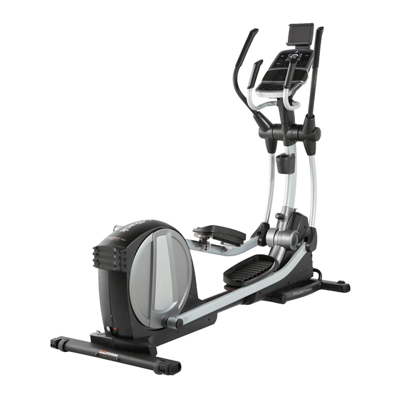
Model No. 23888.1
Serial No.
Write the serial number in the space
above for reference.
Serial
Number
Decal
ACTIVATE YOUR
WARRANTY
To register your product and
activate your warranty today,
go to my.nordictrack.com.
CUSTOMER CARE
For service at any time, go to
nordictrackservice.com.
Or call 1-800-TO-BE-FIT
(1-800-862-3348)
Mon.–Fri. 6 a.m.–6 p.m. MT
Sat. 8 a.m.–12 p.m. MT
Please do not contact the store.
CAUTION
Read all precautions and
instructions in this manual before
using this equipment. Keep this
manual for future reference.
USER'S MANUAL
Advertisement
Table of Contents

Related Manuals for NordicTrack SpaceSaver SE5i


Summary of Contents for NordicTrack SpaceSaver SE5i
- Page 1 Serial Number Decal ACTIVATE YOUR WARRANTY To register your product and activate your warranty today, go to my.nordictrack.com. CUSTOMER CARE For service at any time, go to nordictrackservice.com. Or call 1-800-TO-BE-FIT (1-800-862-3348) Mon.–Fri. 6 a.m.–6 p.m. MT Sat. 8 a.m.–12 p.m. MT Please do not contact the store.
-
Page 2: Table Of Contents
NORDICTRACK and IFIT are registered trademarks of ICON Health & Fitness, Inc. App Store is a trademark of Apple Inc., registered in the U.S. and other countries. Android and Google Play are trademarks of Google Inc. The BLUETOOTH word mark and logos are registered trademarks of Bluetooth SIG, Inc. -
Page 3: Important Precautions
IMPORTANT PRECAUTIONS WARNING: To reduce the risk of serious injury, read all important precautions and instructions in this manual and all warnings on your elliptical before using your elliptical. ICON assumes no responsibility for personal injury or property damage sustained by or through the use of this product. - Page 4 STANDARD SERVICE PLANS...
-
Page 5: Before You Begin
BEFORE YOU BEGIN Thank you for selecting the revolutionary reading this manual, please see the front cover of this NORDICTRACK SPACE SAVER SE 5I elliptical. The manual. To help us assist you, note the product model ® SPACE SAVER SE 5I elliptical provides an impressive number and serial number before contacting us. -
Page 6: Assembly
Do not dispose of the packing wrenches. To avoid damaging parts, do not use materials until you finish all assembly steps. power tools. 1. Go to my.nordictrack.com on your computer and register your product. • documents your ownership • activates your warranty •... - Page 7 3. If there is a shipping support attached to the Front of the Frame (1), remove the screws from the shipping support, and discard the screws and the shipping support. With the help of another person, place some packing inserts from the packing material under the Frame (1) so that the Frame is lifted off the floor.
- Page 8 5. Rotate the Right Upper Body Arm (9) to the upright position. Attach the Right Upper Body Arm (9) to the Right Upper Body Leg (6) with an M10 x 50mm Screw (95). IMPORTANT: Tighten the indicated M10 x 45mm Screw (78). Next, press the Upper Body Arm Cover (20) downward and turn it so that it is flush with the Right Leg Front and Rear Covers (11, 15).
-
Page 9: How To Use The Elliptical
HOW TO USE THE ELLIPTICAL HOW TO PLUG IN THE POWER ADAPTER Next, pull the upright (D) forward IMPORTANT: If the elliptical has been exposed to slightly, lift the cold temperatures, allow it to warm to room tem- latch (E), and then perature before you plug in the power adapter. - Page 10 HOW TO EXERCISE ON THE ELLIPTICAL See HOW TO MOVE THE ELLIPTICAL on page 9 and lower the upright to the folded position. To mount the elliptical, hold the handlebars (H) or the upper body arms (I) and step onto the pedal (J) that is Then, lift the handle on the front stabilizer (G) and tip in the lower position.
- Page 11 CONSOLE DIAGRAM When you use the manual mode of the console, you can change the resistance of the pedals with the touch of a button. While you exercise, the console will display continu- ous exercise feedback. You can even measure your heart rate using the handgrip heart rate monitor or a compatible heart rate monitor.
- Page 12 HOW TO USE THE MANUAL MODE Calories per Hour (Cals/Hr)—This display will show the approximate number of calories you are 1. Begin pedaling or press any button on the burning per hour. console to turn on the console. Distance—This display will show the distance that When you turn on the console, the display will turn you have pedaled in miles (mi) or kilometers (km).
- Page 13 Scan Mode and Priority palms resting against the contacts. Avoid moving Mode—The calories and watts your hands or gripping the contacts tightly. displays will appear in an alternating cycle (scan mode). When your pulse is detected, your heart rate will appear in the display.
- Page 14 HOW TO USE AN ONBOARD WORKOUT As you exercise, you will be prompted to keep your pedaling speed near the target speed for the 1. Begin pedaling or press any button on the current segment. When the words GO FASTER console to turn on the console.
- Page 15 HOW TO CONNECT YOUR TABLET TO THE 5. Disconnect your tablet from the console if CONSOLE desired. The console supports BLUETOOTH connections to To disconnect your tablet from the console, first tablets via the iFit Bluetooth Tablet app and to compat- select the disconnect option in the iFit Bluetooth ible heart rate monitors.
- Page 16 HOW TO USE THE SOUND SYSTEM HOW TO CHANGE CONSOLE SETTINGS To play music or audio books through the console 1. Select the settings mode. sound system while you exercise, plug a 3.5 mm male to 3.5 mm male audio cable (not included) into the To select the settings mode, press the Settings jack on the console and into a jack on your personal button.
-
Page 17: Fcc Information
FCC INFORMATION This equipment has been tested and found to comply with the limits for a Class B digital device, pursuant to Part 15 of the FCC Rules. These limits are designed to provide reasonable protection against harmful interference in a residential installation. This equipment generates, uses, and can radiate radio frequency energy and, if not installed and used in accordance with the instructions, may cause harmful interference to radio communications. -
Page 18: Maintenance And Troubleshooting
MAINTENANCE AND TROUBLESHOOTING MAINTENANCE Look into the access opening and locate the Reed Switch (58). Rotate the Pulley (66) until a Magnet (41) Regular maintenance is important for optimal is aligned with the Reed Switch. Note: For clarity, the performance and to reduce wear. Inspect and properly shields are shown removed in the drawing below. - Page 19 HOW TO ADJUST THE DRIVE BELT See the lower drawing at the left. Remove the four M4 x 16mm Screws (not shown) from the Large If the pedals slip while you are pedaling, even while the Storage Foot (27), and then remove the Large resistance is adjusted to the highest setting, the drive Storage Foot.
-
Page 20: Exercise Guidelines
EXERCISE GUIDELINES Burning Fat—To burn fat effectively, you must exer- WARNING: cise at a low intensity level for a sustained period of Before beginning this time. During the first few minutes of exercise, your or any exercise program, consult your physi- body uses carbohydrate calories for energy. - Page 21 SUGGESTED STRETCHES The correct form for several basic stretches is shown at the right. Move slowly as you stretch; never bounce. 1. Toe Touch Stretch Stand with your knees bent slightly and slowly bend forward from your hips. Allow your back and shoulders to relax as you reach down toward your toes as far as possible.
- Page 22 NOTES...
-
Page 23: Part List
PART LIST Model No. 23888.1 R1217A Key No. Qty. Description Key No. Qty. Description Frame Small Storage Foot Upright Idler Rear Upright Cover Small Spacer Console Resistance Motor Accessory Tray Handle Cover Right Upper Body Leg M4 x 12mm Washer Head Screw Eddy Mechanism Clamp Left Upper Body Arm... - Page 24 Key No. Qty. Description Key No. Qty. Description Left Upper Body Leg 3/16" x 3/4" Screw Upright Axle Crank Arm Spacer B M8 x 20mm Bolt Mount/Screw Power Adapter – User’s Manual M12 Washer – Assembly Tool M12 Split Washer Note: Specifications are subject to change without notice.
-
Page 25: Exploded Drawing
EXPLODED DRAWING A Model No. 23888.1 R1217A... - Page 26 EXPLODED DRAWING B Model No. 23888.1 R1217A...
- Page 27 EXPLODED DRAWING C Model No. 23888.1 R1217A...
-
Page 28: Ordering Replacement Parts
ORDERING REPLACEMENT PARTS To order replacement parts, see the front cover of this manual. To help us assist you, please be prepared to provide the following information when contacting us: • the model number and serial number of the product (see the front cover of this manual) •...