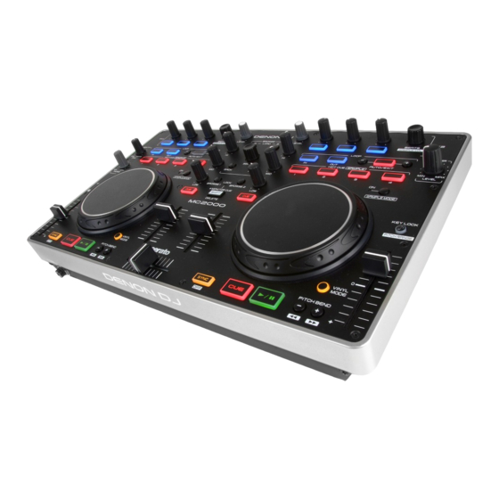
Denon MC2000 Service Manual
Dj controller
Hide thumbs
Also See for MC2000:
- Quick setup manual (2 pages) ,
- Quick start manual (9 pages) ,
- Owner's manual (31 pages)
Table of Contents
Advertisement
MODEL
MC2000
• For purposes of improvement, specifications and design are subject to change without notice.
• Please use this service manual with referring to the operating instructions without fail.
• Some illustrations using in this service manual are slightly different from the actual set.
S0620-0V03DM/DG1302
SERVICE MANUAL
JP
P P P
DJ Controller
D&M Holdings Inc.
E3
E2
EK
Ver. 3
Please refer to the
MODIFICATION NOTICE.
EA
E1
E1K E1C
Advertisement
Table of Contents

Related Manuals for Denon MC2000


Summary of Contents for Denon MC2000
- Page 1 MODIFICATION NOTICE. SERVICE MANUAL MODEL E1K E1C MC2000 P P P DJ Controller • For purposes of improvement, specifications and design are subject to change without notice. • Please use this service manual with referring to the operating instructions without fail.
-
Page 2: Table Of Contents
CONTENTS SAFETY PRECAUTIONS ............3 NOTE FOR SCHEMATIC DIAGRAM .........4 TECHNICAL SPECIFICATIONS ..........5 DIMENSION ................5 DISASSEMBLY ................6 SPECIAL MODE ..............12 1. Special mode setting ............12 2. Version Up mode ..............12 3. Version indicate mode ............13 4. Adjusting mode of the touch sense sensitivity .....14 5. -
Page 3: Safety Precautions
SAFETY PRECAUTIONS The following items should be checked for continued protection of the customer and the service technician. LEAKAGE CURRENT CHECK Before returning the set to the customer, be sure to carry out either (1) a leakage current check or (2) a line to chassis resistance check. -
Page 4: Note For Schematic Diagram
NOTE FOR SCHEMATIC DIAGRAM WARNING: Parts indicated by the z mark have critical characteristics. Use ONLY replacement parts recommended by the manufacturer. CAUTION: Before returning the set to the customer, be sure to carry out either (1) a leakage current check or (2) a line to chassis resistance check. If the leakage current exceeds 0.5 milliamps, or if the resistance from chassis to either side of the power cord is less than 460 kohms, the set is defective. -
Page 5: Technical Specifications
TECHNICAL SPECIFICATIONS n Audio n General (0 dBu=0.775 Vrms, 0 dBV =1 Vrms) • LINE inputs 1 Stereo USB MIDI input/output: IN: 1ch, OUT: 1ch MIDI 1.0, USB B Unbalanced RCA terminal Channel fader: PPM 7 Point LED –20 – +10 dB, Peak Input impedance: 10 kΩ... -
Page 6: Disassembly
DISASSEMBLY • Disassemble in order of the arrow in the following figure. • In the case of the re-assembling, assemble it in order of the reverse of the following flow. • In the case of the re-assembling, observe "attention of assembling". •... - Page 7 Disassembly Illustration 1.Dismantle the packaging, taking out the machine . 2. Remove the screws form bottom base . SCREW *14 螺絲*14 602-XM610-522 3. Disconnect the FCC cable,then remove the panel from bottom base . CONTROL PCB I/O PCB CN300A Remove the FFC cable from I/O PCB(REF NO.CN300A)
- Page 8 Disassembly Illustration 4.Remove the rotary knob *20 and push knob*5 from panel . 5.Remove the screws *14 from panel . Screw *14 螺絲*14 602-HP1010K-182 panel 面板 6-1. Remove the nuts*20 and washer *20 Nut *20 from panel . Washer *20 6-2.
- Page 9 Disassembly Illustration 7-1.Remove the screws *21 from control pcb ass'y . 7-2.Remove the ground plates *6 and the screws*6 . 8. Remove the solder *2 ,then remove the control pcb ass'y . SOLDER* 9.Remove the square buttons and rotary buttons .
- Page 10 Disassembly Illustration 10-1.Remove the wheel ass'y*2 . E-RING 10-2. Remove the spring & wire ass'y *2 . 11-1. Remove the screws *7 from the bottom base. 11-2. Remove the nut *2 and washer *2 from phone jack. 11-3. Remove the rotary knob(small) *2 .
- Page 11 Disassembly Illustration 11-4. Remove the screws *4 from I/O pcb ass'y, Screw *2 螺絲*2 then remove the I/O pcb ass'y . 602-B300-041 Screw *2 自攻螺絲*2 602-QMX2BPM-322 I/O pcb ass'y I/O基板整組...
-
Page 12: Special Mode
SPECIAL MODE 1. Special mode setting Turns on MC3000 while pressing buttons A, B and C. Mode Contents Version Up mode Firmware Upgrade Version indicate mode Firmware version display Adjusting mode of the touch sense sensitivity Adjust sensitivity of JOG wheel. Initialize mode 5, 6 Return to factory default setting. -
Page 13: Version Indicate Mode
3. Version indicate mode Confirmation of version Pressing (SHIFT+BROWSE1+FWD) at the same time, then connect MC2000 to a PC for confirmation of F/W version. How to read the version number Firmware Version LED (Ver A.XYZ. After Ver1.000, it is commercial version). -
Page 14: Adjusting Mode Of The Touch Sense Sensitivity
“-4” is the lowest sensitivity, and “+4” is the highest sensitivity. The default setting is “0”. (1) Pressing (SHIFT+LOAD A+LOAD B) at the same time, then connect MC2000 to a PC. (2) Press CUE, and switch the jog wheel that you want to adjust. -
Page 15: Adjusting Interval Time Of Midi Command Transmission
In this case, use the following operation to set the MIDI command transmission interval time to a suitable value. (1) Pressing (SHIFT+BROWSE1 +BROWSE2) at the same time, then connect MC2000 to a PC . The following LED turns on, and the unit switches to the setting mode for MIDI command transmission interval time. -
Page 16: Sw, Volume, Encoder And Led Test
7. SW, VOLUME, ENCODER and LED TEST Operating check procedure for the SW/VOLUME/ENCODER and LEDs on this unit with MIDI-OX. [1] MIDI-OX Installation and Settings Install MIDI-OX on the PC, and configure the PC environment. (1) Download MIDI-OX (freeware). Download from the URL below. URL: www.midiox.com/ (2) Install MIDI-OX on the PC. - Page 17 (7) Open the [Actions] menu and check that “Stop Display” is shown. If “Start Display” is shown, click “Start Display” so that “Stop Display” is shown. [2] Check the SW/VOLUME/ENCODER When SW/VOLUME/ENCODER is operated on this unit, the corresponding MIDI command is shown on MIDI-OX. If the MIDI command is not shown on MIDI-OX even when the panel of this unit is operated, check the following.
- Page 18 (2) Check whether the USB audio device is selected. Check that it is highlighted black. If it is not highlighted, select it so that it is highlighted black. (3) Screen display when the EFX.1 button on this unit is switched ON-OFF. Pressed button DATA1 column display EFX.1...
- Page 19 (4) Next, this is the screen display when the EFX.1 knob is moved either to the left or right. Operated knob DATA1 column display EFX.1 For details on the correspondence between operation on this unit and the contents of the screen display, see the "MIDI command list"...
- Page 20 [3] Check the LED When the MIDI command is sent from MIDI-OX, the LED lights/flashes/off/Dimmer. (1) Select [View] menu - [Control Panel]. (2) These are explained in order of LED lights/off/flashes/Dimmer. Example1 : When lighting the EFX.1 button on DECK A In the MIDI-OX Control Panel, set the following parameters.
- Page 21 Example2 : When flashing the EFX.1 button on DECK A In the MIDI-OX Control Panel, set the following parameters. Control Event Channel Value 76) --- When the Enter button on the PC keyboard is pressed, the EFX.1 button on the unit flashes. Example3 : When off the EFX.1 button on DECK A In the MIDI-OX Control Panel, set the following parameters.
- Page 22 Example4 : When dimming the EFX.1 button on DECK A In the MIDI-OX Control Panel, set the following parameters. Control Event Channel Value 74) Brightness When the Enter button on the PC keyboard is pressed, the EFX.1 button on the unit dims. b Some of the LEDs such as those for Meter or Ducking use the following parameters to light/switch off.
-
Page 23: When The Microprocessor Is Replaced With A New One
Refer to "Update procedure" or "writing procedure", when you write the software. PROCEDURE FOR UPGRADING THE VERSION OF THE FIRMWARE 1. preparation (1) Connect the computer by USB cable. MC2000 : Type B (2) UPDATER Dowload Dennon SDI site. for Windows : DDJUpdater-2.0.msi for Mac : DDJ Updater.app... - Page 24 (2) Click the Next. (3) Check the I accept the terms of the license agreement,and Click the Next. (4) Click the Next.
- Page 25 (5) Click the Next. (6) Click the Next. (7) The Setup Status bar appears.
- Page 26 (1) Connect the USB cable from PC to the unit. (2) Press the POWER button to turn on while pressing buttons BACK, FWD and SHIFT. (3) MC2000 will enter versionup mode. CUE 1 will light. (4) Run the "DDJ Updater” on desktop of PC.
- Page 27 (5) Click the File menu. And click the Open. Select the latest firmware. MC2000 (6) Click the Load. MC2000 MC2000...
- Page 28 (7) The Setup Status bar appears. MC2000 MC2000 (8) Click the OK. MC2000...
- Page 29 (9) Click the Execute. MC2000 ver. 1.000 MC2000 ver. 1.100 (10) The Setup Status bar appears. MC2000 MC2000 MC2000 indicates state of updating. CUE 1: Update Ready, CUE 2: Update Data(0%), CUE 3: Update Data(50%), CUE 4: Update Data(100%)
- Page 30 (11) Click the OK. MC2000 (12) When version up finished, this unit is usual mode automatically. Failure to upgrade to the PC "Version up was not completed." is displayed. Then "Execute" click again.
- Page 31 (1) Unit is not connected or if the unit is not upgraded mode as shown below. Please try again step (1). (2) If the file version is not loaded "File is not ready." Is displayed. Please try again step (5). MC2000 [Caution] During the loading and upgrading the power OFF and set, PC or please do not remove the cable connection.
-
Page 32: Trouble Shooting
TROUBLE SHOOTING FLOW CHART NO.1 (405-MC2-3059 : I/O UNIT) The power cannot be turned on. Is the fuse normal? Refer to FLOW CHART NO.2 <The fuse blows out.>. Is the FFC(14pin:CN300) connected correctly? Reconnect normaly. Check IC400 and perifery circuit, and replace it if defective. Is +5V or more supplied to 7pin of CPU(IC400)? (L400, C416, C447, C448) Replace the IC400. - Page 33 FLOW CHART NO.3 (405-MC2-3059 : I/O UNIT) D3.3V is not outputted. Is U5V line voltage normal? Refer to FLOW CHART NO.2 <The fuse blows out.>. Check IC6 and the periphery circuit, and replace it if defective. FLOW CHART NO.4 (405-MC2-3058 : CONTROL UNIT) D5V is not outputted.
- Page 34 FLOW CHART NO.6 (405-MC2-3059 : I/O UNIT) +6.5V is not outputted. Is the fuse normal? Refer to FLOW CHART NO.2 <The fuse blows out.>. Check IC4 and the periphery circuit, and replace it if defective. FLOW CHART NO.7 (405-MC2-3059 : I/O UNIT) -6.5V is not outputted.
- Page 35 FLOW CHART NO.8 (405-MC2-3058 : CONTROL UNIT) The key operation is not functioning. Are the contact point and the installation state of the key switches (SW400 - SW448) and rotary encoder (SW449 - Re-install the switches correctly or replace the poor switch. SW451) nomal? Check the Q400 - Q405, Q410 - Q417 and their periphery, Does LED (D460 - D498) light correctly?
- Page 36 FLOW CHART NO.9 (405-MC2-3059 : I/O UNIT, 405-MC2-3058 : CONTROL UNIT) Master output is not outputted correctly. Is the FFC(14pin:CN300) connected correctly? Reconnect normaly • Set the AUX IN LEVEL volume to "12:00". Are audio signals output to 7pin(Lch),1pin(Rch) of IC100, Check periphery circuit of IC100 from JK100 / IC102 from IC102 when an audio signal of 1 kHz 0 dBV is input externally IC100, and service it if defective.
- Page 37 FLOW CHART NO.10 (405-MC2-3058 : CONTROL UNIT) JOG WHEEL is not operating. (BEND function is not operating.) Is D5V outputted 11pin, 12pin of CN300 Connect the FFC (14pin:CN300) correctly. (Refer to Fig.5 of the 40 page.) Is encoder waveform(0-3.3V) outputted to9pin, 10pin, 45pin, Check perifery circuit of Q406, Q407, Q408, Q409, replace it 51pin of IC400, when JOG WHEEL is turned.
- Page 38 FLOW CHART NO.11 (405-MC2-3058 : CONTROL UNIT) JOG WHEEL is not operating. (SCRATCH function is not operating.) Refer to FLOW CHART NO.10 <JOG WHEEL is not Is BEND function operating? operating. (BEND function is not operating.)>. Check the periphery circuit of IC405 and IC406 and replace it Is reference waveform outputted at 2pin, 6pin and 12pin of if defective.
- Page 39 TroubleShooting Figure 1 Fig.1 TroubleShooting Figure 2 Fig.2 TroubleShooting Figure 3 Fig.3...
- Page 40 TroubleShooting Figure 4 Fig.4 TroubleShooting Figure 5 Fig.5 TroubleShooting Figure 6 Fig.6...
-
Page 41: Wiring Diagram
WIRING DIAGRAM Point To Point Wiring Diagram CONTROL CN300A CN400 CN103 CROSS FADER PCB I/O PCB CN300A W100 CN100 PHONE... - Page 42 Personal notes:...
-
Page 43: Block Diagram
Headphone(40 ohm) USB PortB 0dBu LRCK SPI Control +7.74dB Phones PCB 3dBV 2nd order LPF PCM1755 +2.77dB 2nd order LPF Title MC2000 PCM1755 Size Number Revision 3dBV BLOCK 0.11 Date: 2012/6/21 1001214 Sheet of Gavin File: \\..\MC2000 Block(V0.11).Sch Drawn By:... -
Page 44: Power Block Diagram
POWER BLOCK DIAGRAM... -
Page 45: Level Diagram
LEVEL DIAGRAM Ref.-10dB MONITOR -3.17dB +10.73dB NJM4580 NJM4580 Ref.-10dB VOLUME +15.72dB NJM4580 Ref.-7.82dB Max.-27.56dB VOLUME +32.26dB +20.27dB NJM2068 NJM2068 +0dB Master Out +7.74dB Limit +3dBV NJM4580 PCM1755 +2.77dB +1.36dB Limit +3dBV NJM4580 NJM4556 +0dB PCM1755 PHONES -10dB Max Input Level Max.Output Level 0dBFS +12dBV... -
Page 46: Printed Wiring Boards
PRINTED WIRING BOARDS PRINTED WIRING BOARDS CONTROL CONTROL / PHONES (COMPONENT SIDE) (FOIL SIDE) 405-MC2-3058/3060 鉛フリー半田 鉛フリー半田 半田付けには、鉛フリー半田 (Sn-Ag-Cu) を使用してください。 半田付けには、鉛フリー半田 (Sn-Ag-Cu) を使用してください。 Lead-free Solder Lead-free Solder When soldering, use the Lead-free Solder (Sn-Ag-Cu). When soldering, use the Lead-free Solder (Sn-Ag-Cu). - Page 47 PRINTED WIRING BOARDS CONTROL CONTROL / PHONES (FOIL SIDE) (COMPONENT SIDE) 405-MC2-3058/3060 鉛フリー半田 鉛フリー半田 半田付けには、鉛フリー半田 (Sn-Ag-Cu) を使用してください。 半田付けには、鉛フリー半田 (Sn-Ag-Cu) を使用してください。 Lead-free Solder Lead-free Solder When soldering, use the Lead-free Solder (Sn-Ag-Cu). When soldering, use the Lead-free Solder (Sn-Ag-Cu).
-
Page 48: I/O
PRINTED WIRING BOARDS I / O (COMPONENT SIDE) (FOIL SIDE) 405-MC2-3059 鉛フリー半田 鉛フリー半田 半田付けには、鉛フリー半田 (Sn-Ag-Cu) を使用してください。 半田付けには、鉛フリー半田 (Sn-Ag-Cu) を使用してください。 Lead-free Solder Lead-free Solder When soldering, use the Lead-free Solder (Sn-Ag-Cu). When soldering, use the Lead-free Solder (Sn-Ag-Cu). - Page 49 PRINTED WIRING BOARDS I/O s I / O (FOIL SIDE) (COMPONENT SIDE) CROSS FADER 405-MC2-3059 鉛フリー半田 鉛フリー半田 (COMPONENT SIDE) 半田付けには、鉛フリー半田 (Sn-Ag-Cu) を使用してください。 半田付けには、鉛フリー半田 (Sn-Ag-Cu) を使用してください。 Lead-free Solder Lead-free Solder When soldering, use the Lead-free Solder (Sn-Ag-Cu). When soldering, use the Lead-free Solder (Sn-Ag-Cu). 405-MC6000-2785...
-
Page 50: Schematic Diagrams (1/2)
IN-R CUE1-R FX1-3 LOAD-A DELETE-L SYNC-R C402 SW406 SW400 SW412 SW418 SW424 SW430 D400 D406 D412 D418 D424 D430 1SS355 1SS355 1SS355 1SS355 1SS355 1SS355 R411 10K C473 OUT-R FX1-1 LOAD-B CUE1-L CUE-R CUE2-R 0.01 C400 SW407 SW401 SW413 SW419 SW425 SW431 C474... -
Page 51: I/O Unit
-3.17dB C105 +6V5 +7.74dB R105 IC100B 75K,0.5% C109 4580 +6V5 +10.73dB C133 R149 R101 +0dB 10/25 C137 R107 R143 2.2K,0.5% IC101B C104 15K,0.5% C135 2.2K,0.5% -6V5 4580 +6V5 C143 VR100B 22/16 C129 IC105B 820P C103 20K(15A) C108 C139 R145 470P C101 C125 C145... -
Page 52: Exploded View
EXPLODED VIEW WARNING: Parts marked with this symbol have critical characteristics. Use ONLY replacement parts recommended by the manufacturer. 印の部分は安全を維持するために重要 な部品です。従って交換時は必ず指定の 部品を使用してください。... -
Page 53: Parts List Of Exploded View
WHEEL PLATE 300-2000-1833 SPRING(SUS304, ∮ 0.3,L=6) 603-M1-384 SCWER(SAE1018,STS,2.0*3) 602-STS2003-677 BASE ASS'Y 703-2000-1370 CROS FADER PCB ASS'Y 704-6000-9603 I/O PCB ASS'Y 704-MC2000-A347 CONTROL PCB ASS'Y 704-MC2000-A348 PHONE PCB ASS'Y 704-MC2000-A350 9 941412005080P PUSH KNOB(MIDDLE) 100-UDJ3EB-2213 00D9587012907 ROTATY KNOB(ABS,BLACK) 100-300-2226 00D9587013401 PUSH KNOB... - Page 54 Ref. No. Part No. Part Name Remarks HANPIN Q'ty New PULLEY WASHER( ∮ 11.6*76*0.25t) 606-F200-003 E RING 606-DJ3000-105 FOOT(PORON,BLACK, ∮ 15*3t) 612-HV3500K-055 CUSHION(75*7*0.3t,BLACK) 612-IMR-295 CUSHION(64*7*0.3t,BLACK) 612-IM-296 SPACER 612-2000-440 SCREW(3*5 P=0.5) 602-B300-041 SCREW(SAE1018,PTP,M2.6*L8) 602-SL24F-099 SCREW(STP,M2*P0.4*L6) 602-HP1010K-181 SCREW( ∮ 5,L=8) 602-HP1010K-182 SCREW(SAE1018,BTB, ∮ 3*L5) 602-QMX2BPM-322 SCREW(SAE1018,ISOF, ∮...
-
Page 55: Packing View
PACKING VIEW PARTS LIST OF PACKING & ACCESSORIES z Parts indicated by "nsp" on this table cannot be supplied. z Parts indicated by the " ★ " mark are not illustrated in the exploded view. z The parts listed below are only for maintenance. Therefore they might differ from the parts used in the unit in appearances or dimensions. Note: The symbols in the column "Remarks"... - Page 56 Ref. No. Part No. Part Name Remarks HANPIN Q'ty New I/B ASS' Y 701-M2000EM-5237 5 35201016500AP IM SOFTWARE DISC 429-M2000EM-139 5 941342100030P SERATO DJ INTRO DISC 429-M2000EM-145 5 54111092600AP QUICK SETUP GUIDE 502-M2000EM-3239 WARRANTY(EN.) 502-M2000EM-3240 CERTIFICATE(JP.) 502-M2000EM-3241 PE BAG 505-DJ2500H-014 6 941414100120P CARTON HANDLE 100-U25G-1157A 7 941414100130P HANDLE BASE...
-
Page 57: Semiconductors
SEMICONDUCTORS Only major semiconductors are shown. General semiconductors etc. are omitted from list. The semiconductors which have a detailed drawing in a schematic diagram are omitted from list. IC Block Diagram 1. IC's 74AHC595DR,SOP-16 (IC404) LD1117AC-ADJ-AA3,SOT-223 (IC6) - Page 58 IC Block Diagram NJM-2068M-TE2,SOP8 (IC103) – 1N1 OUT2 – – + IN1 – 1N2 + IN2 BD4740G-TR,SMP5 (IC005) BLOCK DIAGRAM PIN NO.,PIN NAME N.C. Pin NO. Pin Name N.C. Vout Vref Vout NOTE: Substrate Pin should be connected with GND * Please refer to Technical note concerning application circuit,and etc.
- Page 59 IC Block Diagram PIC16F616-I/SL,SOIC-16 (IC405/IC406) NJM4556A (IC109) 417-3113-018 NJM4556A...
- Page 60 IC Block Diagram ICS501MLFT (IC304) S1:0 PLL Clock Multiplier X1/ICLK Circuitry Crystal or Crystal and ROM Clock input Oscillator Optional crystal capacitors COMP FREQ PGND SENSOR LTH-301-07U (D456/D457/D458/D459)
- Page 61 IC Block Diagram NJM-4580M-TE2,SOP-8 (IC100~IC102, IC104~IC108) (BA05FP-E2,TO-252 (IC3)
- Page 62 IC Block Diagram TUSB3200ACPAH,PQFP52 (IC302) Functional Block Diagram DMA Controller USB Buffer Manager USB Serial Interface Engine DMA0 CODEC Port C–Port Interface DMA1 2K x 8 SRAM DMA2 DMA3 Suspend CLOCKS /Resume Logic Control/Status 6Mhz Registers I 2 C I 2 C Bus 8052 Core Control 4K ROM...
- Page 63 IC Block Diagram PCM1755DBQR,SSOP-16 TI (IC300/IC301)
- Page 64 IC Block Diagram 74HC4052D/74HC4052DT,SMD (IC402/IC403) TPS54232 (IC2)
- Page 65 u-Pro Port List (Pin Function) STM8S207M Terminal Functions (IC400) STM8S207M Pin number Pin name Type Input/Output Main Function NRST Reset PA1/OSCIN Resonator/crystal in PA2/OSCOUT Resonator/crystal out VSSIO_1 I/O ground Digital ground VCAP 1.8 V regulator capacitor Digital power supply VDDIO_1 I/O power supply PA3/TIM2_CH3 Output...
- Page 66 u-Pro Port List (Pin Function) STM8S207M Pin number Pin name Type Input/Output Main Function PC3/TIM1_CH3 Input PC3(PB2) PC4/TIM1_CH4 Output PC4(STCP) PC5/SPI_SCK Output PC5(SHCP) VSSIO_2 I/O ground VDDIO_2 I/O power supply PC6/SPI_MOSI Output PC6(DS) PC7/SPI_MISO Output PC7(/INT) PG0/CAN_TX Input PG0(KR1) PG1/CAN_RX Input PG1(KR2) Input...
- Page 67 u-Pro Port List (Pin Function) PCM1755D (IC300/IC301) TERMINAL NAME I/O DESCRIPTION TERMINAL NO. Audio data bit clock input DATA Audio data digital input LRCK L-channel and R-channel audio data latch enable input DGND Digital ground Analog power supply, 5 V VOUTL Analog output for L-channel VOUTR...
-
Page 68: Parts List Of P.c.b. Unit
941263100680P LED(LTL1CHJEDNN,RED) 410-DJ5000-253 D460-D498 LED HOLDER(LED3-1A-B,H=1.5mm,BLACK) 504-HDJ2000-097 D499 DIODE(SMAJ6.0A,400W/6.0V,DO-214AC) 414-UDJ200-284 D500-503 941209000470S ESD DIODE(RSB6.8S 150mW.6.8V EMD2 ROHM) 414-DJ1100G-207 IC400 941243101300P CONTROL IC ASS'Y 704-MC2000-A349 IC402,403 IC(74HC4052D/74HC4052DT,SMD) 417-QSPAND-432 IC404 00D9587058709 IC(74AHC595DR,SOP-16) 417-HDJ9800-643 IC405,406 941243004220P IC(PIC16F616-I/SL,SOIC-16) 417-RMP3-936 Q400-405 941212004520P CHIP TRANSISTOR(2SB1424T100R) 416-MC6000-375... - Page 69 Ref. No. Part No. Part Name Remarks HANPIN Q'ty ELEC. CAPACITOR(470uF/10V,M, 105°C,TAPING 8*12) C416 413-HT8015-169 (Cd,Pb,Hg,Cr) C419 CHIP CAPACITOR(0.1uF/50V,Z) 413-DCM280-773 C422-436 CHIP CAPACITOR(0.01uF/50V,J,0603 TAP,NPO) 413-DCM280-889 C437-440 CERAMIC CAPACITOR(0.01uF/50V,Z,TAPING,Z5V) 413-3113-028 C441-443 CHIP CAPACITOR(0.01uF/50V,J,0603 TAP,NPO) 413-DCM280-889 C444,445 CERAMIC CAPACITOR(0.01uF/50V,Z,TAPING,Z5V) 413-3113-028 C446 941135500070P TANTALUM CAPACITOR(0.68uF/50V,K,TAPING) 413-MAIE-1211 C447 CHIP CAPACITOR(0.47uF/16V,Z)
- Page 70 Ref. No. Part No. Part Name Remarks HANPIN Q'ty R521 CHIP RESISTOR(680 OHM,1/10W,J,TP ,50V) 412-900-1060 R522 CHIP RESISTOR(270 OHM,1/10W,J,TP ,50V) 412-007USB-698 R523 CHIP RESISTOR(680 OHM,1/10W,J,TP ,50V) 412-900-1060 R524 CHIP RESISTOR(220 OHM,1/10W,0603 ,J,TP 50V) 412-CDVD2001-521 R525-527 CHIP RESISTOR(270 OHM,1/10W,J,TP ,50V) 412-007USB-698 R528,529 CHIP RESISTOR(51KOHM,1/10W,J,TP 0603,50V) 412-900-977...
-
Page 71: I/O P.c.b Ass'y
I/O P.C.B ASS'Y Ref. No. Part No. Part Name Remarks HANPIN Q'ty SEMICONDUCTORS GROUP D002-004 DIODE(1N5819(GW)/1N5819,TAPING 52mm) 414-DFX1-144 D006,007 SWITCHING DIODE(ISS355VM 1.7*1.25MM) 414-CD1000-075A D030 DIODE(1N5819(GW)/1N5819,TAPING 52mm) 414-DFX1-144 D301 DIODE(1N5819(GW)/1N5819,TAPING 52mm) 414-DFX1-144 D302-305 ESD DIODE(RSB6.8S 150mW.6.8V EMD2 ROHM) 414-DJ1100G-207 D306,307 DIODE(SMAJ6.0A,400W/6.0V,DO-214AC) 414-UDJ200-284 D308-311 941209000470S ESD DIODE(RSB6.8S 150mW.6.8V EMD2 ROHM) - Page 72 Ref. No. Part No. Part Name Remarks HANPIN Q'ty C122 CHIP CAPACITOR(330pF/50V,J,0603 TAP,NPO) 413-900-925 C123,124 CHIP CAPACITOR(0.1uF/50V,Z) 413-DCM280-773 C125,126 ELEC. CAPACTIOR(10uF/25V,M,105°C,TAPING 5*11) 413-3113-052 C127,128 CHIP CAPACITOR(3300pF/50V,K,0603 TAP,X7R) 413-DCM280-770 C129,130 CHIP CAPACITOR(470pF/50V,J,0603 TAP,NPO) 413-007USB-786 C131,132 CHIP CAPACITANCE(560pF/50V,J,NPO,0603 TAP) 413-TU3-1104 C133,134 ELEC. CAPACTIOR(10uF/25V,M,105°C,TAPING 5*11) 413-3113-052 C135,136 CHIP CAPACITOR(0.1uF/50V,Z)
- Page 73 Ref. No. Part No. Part Name Remarks HANPIN Q'ty R116,117 CHIP RESISTOR(470 OHM,1/10W,0.5%,TP 0603,50V) 412-MC2-1538 R118,119 CHIP RESISTOR(2.4K OHM,1/10W,0.5%,TP 0603,50V) 412-MC2-1540 R122,123 CHIP RESISTOR(0 OHM,1/10W3,J,TP,50V) 412-CDVD2001-552 R124 CHIP RESISTOR(910 OHM,1/10W,0603,J,TP ,50V) 412-007USB-691 R125,126 CHIP RRESISTOR(20K OHM,1/10W,0.5%,TP 0603,50V) 412-MC2-1539 R127-130 CHIP RESISTOR(10K OHM,1/10W,0.5%,TP 0603,50V) 412-MC2-1541 R131 CHIP RESISTOR(18K OHM,1/10W,0.5%,TP 0603,50V)
- Page 74 Ref. No. Part No. Part Name Remarks HANPIN Q'ty z F300 941652500240P CHIP FUSE(1A,63V,1206 TYPE,LEAD FREE) 422-3BPM-070 JK100 941643102290P 2P RCA JACK(RJ-1078B-10-0320A) 420-HDJ7000-045 JK101 941643101360P MIC JACK (6.4,JY-6313-02-340) 420-SMX211-137 JK100 941643102290P 2P RCA JACK(RJ-1078B-10-0320A) 420-HDJ7000-045 JK300 GROUND PLATE 300-2000-1832 JK300 941643004210P USB JACK(USB-B(F),90°,DIP) 420-007USB-150 L002,003...
-
Page 75: Cros Fader P.c.b Ass'y
CROS FADER P.C.B ASS'Y Ref. No. Part No. Part Name Remarks HANPIN Q'ty OTHERS PARTS GROUP 404-HP1010K- CN103 3P SOCKET(CKM2001WV-3P,180°WHTIE) 259A VR101 941674005060P SLIDE VR(RA45D2F-211-17D1-0B20K-0025) 418-MC6000-644 PHONE P.C.B ASS'Y Ref. No. Part No. Part Name Remarks HANPIN Q'ty CAPACITORS GROUP C177,C178 CHIP CAPACITOR(2200pF/50V,J,0603 TAP,X7R) 413-007USB-788... - Page 76 Personal notes:...