Table of Contents
Advertisement
Quick Links
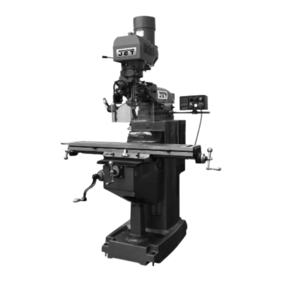
Operating Instructions and Parts Manual
Electronic Variable Speed Turret Mill
Models:
JTM-949EVS/230
JTM-1050EVS2
JTM-949EVS/230 shown
JET
427 New Sanford Road
LaVergne, Tennessee 37086
Ph.: 800-274-6848
www.jettools.com
This .pdf document is bookmarked
Part No. M-690501
Revision E 12/2016
Copyright © 2016 JET
Advertisement
Table of Contents

Related Manuals for Jet JTM-949EVS/230


Summary of Contents for Jet JTM-949EVS/230
- Page 1 This .pdf document is bookmarked Operating Instructions and Parts Manual Electronic Variable Speed Turret Mill Models: JTM-949EVS/230 JTM-1050EVS2 JTM-949EVS/230 shown 427 New Sanford Road LaVergne, Tennessee 37086 Part No. M-690501 Ph.: 800-274-6848 Revision E 12/2016 www.jettools.com Copyright © 2016 JET...
-
Page 2: Warranty And Service
JET sells through distributors only. The specifications listed in JET printed materials and on official JET website are given as general information and are not binding. JET reserves the right to effect at any time, without prior notice, those alterations to parts, fittings, and accessory equipment which they may deem necessary for any reason ®... -
Page 3: Table Of Contents
4.0 About this manual ............................6 5.0 Specifications ..............................7 5.1 Machine dimensions – JTM-949EVS/230, JTM-1050EVS2 ............... 8 5.2 Overview and terminology – JTM-949EVS/230, JTM-1050EVS2 .............. 9 6.0 Set-up and assembly ........................... 10 6.1 Contents of shipping container ......................... 10 6.2 Preparing the mill for service ........................ - Page 4 13.7.2 JTM-949EVS/JTM-1050EVS2 Control Panel Assembly – Parts List ..........40 13.8.1 JTM-949EVS/JTM-1050EVS2 Electrical Box – Exploded View ............41 13.8.2 JTM-949EVS/JTM-1050EVS2 Electrical Box – Parts List ..............41 13.9.1 JTM-949EVS/JTM-1050EVS2 Coolant Pump (Optional) – Exploded View ........42 13.10.1 JTM-949EVS/JTM-1050EVS2 Work Lamp – Exploded View ............42 13.9.2 JTM-949EVS/JTM-1050EVS2 Coolant Pump (Optional) –...
-
Page 5: Safety Warnings
Do not use this turret mill for other than its replaced. intended use. If used for other purposes, JET 17. Do not use power tools in damp/wet locations disclaims any real or implied warranty and holds or other dangerous environments. -
Page 6: About This Manual
If there are questions or comments, please contact your local supplier or JET. JET can also be reached at our web site: www.jettools.com. -
Page 7: Specifications
The specifications in this manual were current at time of publication, but because of our policy of continuous improvement, JET reserves the right to change specifications at any time and without prior notice, without incurring obligations. -
Page 8: Machine Dimensions - Jtm-949Evs/230, Jtm-1050Evs2
5.1 Machine dimensions – JTM-949EVS/230, JTM-1050EVS2 Figure 1: Installation Diagram (JTM-949EVS/230 shown) -
Page 9: Overview And Terminology - Jtm-949Evs/230, Jtm-1050Evs2
5.2 Overview and terminology – JTM-949EVS/230, JTM-1050EVS2 Figure 2: Overview (JTM-949EVS/230 shown) -
Page 10: Set-Up And Assembly
17/19mm Box Wrench * Read and understand the entire Cross Point Screw Driver #2 * contents of this manual before attempting set- Flat Blade Screw Driver #2 * up or operation. Failure to comply may cause Oil Can * Elevating Crank Handle serious injury. -
Page 11: Electrical Connections
Otherwise, perform them in the order listed. Refer to The JTM-949EVS/230 and JTM-1050EVS2 have Figure 3 to help locate items. been pre-wired for 230 volt operation only. 15. Install the table longitudinal and cross-feed... -
Page 12: Lubrication
A – RPM digital readout. 8.0 Lubrication B – Motor direction switch: Has two positions: FWD (forward) and REV (reverse). Setting the Do not operate the mill before switch to FWD will provide clockwise spindle lubricating the machine fully. Failure to rotation. -
Page 13: Control Positions For Milling And Drilling Operations
9.3 Control positions for milling and drilling operations Table 2... -
Page 14: Electronic Variable Speed
9.4 Electronic variable speed 9.7 Quill power feed lever The dial on the EVS control panel controls the main motor speed. Motor RPM is displayed on the LED screen. Do not use power feed at speeds above 3000 R.P.M. 9.5 Spindle brake It is recommended to disengage the The spindle brake lever is located on upper left side of power feed worm gear whenever power feed is not... -
Page 15: Feed Trip Cam Lever
It is recommended that Feed Direction Knob be left in neutral position when not in use. Figure 8 9.9 Feed trip cam lever The Feed Trip Cam Lever (A, Figure 9) is located on left Figure 10 side of head behind the Manual Fine Feed Handwheel (B, Figure 9). -
Page 16: Fine Feed Handwheel
9.14 Fine feed handwheel Tighten the Locknut (I). Ensure Quill Lock (K) is disengaged by rotating When the controls are set for the Fine feed using counter-clockwise. Handwheel position (see Table 2), the Fine Feed Handwheel (A, Figure 10) can be used for manual fine Start spindle (see Table 2): feed control in either upward or downward direction of the quill. -
Page 17: Draw Bar Operation - Changing Tooling
9.17 Draw bar operation – changing 10.0 Adjustments tooling Using the provided wrench, loosen draw bar two or 10.1 Mill head – left/right adjustment three turns (turn counterclockwise) using draw bar hex (Figure 14). Make sure machine base is secured to floor before repositioning mill head. -
Page 18: Mill Head - Fore/Aft Adjustment
Check to make sure mill head is perpendicular to work table. c. Set up a dial indicator in a collet and secure using the draw bar (refer to Figure 18). Figure 19 (JTM-949EVS/230 shown) -
Page 19: Gib Adjustment
10.4.2 Saddle gib adjustment Turn ram pinion (B, Figure 19) with a wrench to slide ram on its ways. The saddle gib adjustment screw is on left front of saddle When desired position is reached, tighten handles (B, Figure 20). Tighten screw until a slight drag is felt (A, Figure 19)[or hex nuts] securely. - Page 20 10. Check for correct operation using the coarse feed Using the cross-feed crank, move table to middle handle. If operating correctly, start drive motor and position. engage power feed mechanism. Verify that power Set up a dial indicator to check cross-feed backlash. feed lever correctly engages and disengages when Gently move cross feed crank back and forth while driven by drive motor.
-
Page 21: Maintenance
11.0 Maintenance Before any intervention on the machine, disconnect it from electrical supply by pulling out plug or switching off main switch. Failure to comply may cause serious injury. 11.1 Lubrication The milling machine is equipped with an automatic lubrication system. The system lubricates the lead screws and ways. An oil cup and grease nipple on the mill head provide lubrication for the spindle bearings and back gear mechanism. -
Page 22: Recommended Speed For Mill And Drill Operations
Non-proprietary parts, such as fasteners, can be found at local hardware stores, or may be ordered from JET. Some parts are shown for reference only, and may not be available individually. -
Page 23: Jtm-949Evs/Jtm-1050Evs2 Upper Head Assembly - Exploded View
13.1.1 JTM-949EVS/JTM-1050EVS2 Upper Head Assembly – Exploded View... -
Page 24: Jtm-949Evs/Jtm-1050Evs2 Upper Head Assembly - Parts List
13.1.2 JTM-949EVS/JTM-1050EVS2 Upper Head Assembly – Parts List Index No Part No Description Size 1 ....JTM949EVS-A01 ..Upper Pulley Housing ..................1 2 ....TS-1504041 ....Hex Socket Cap Screw ..........M8x20 ......4 3 ....JTM949EVS-A03 ..Bull Gear Shifter Pinion Shaft ................ 1 4 .... - Page 25 96 ....JTM949EVS-A96 ..Sensor ......................1 97 ....ZX-S36 ...... Pan Head Screw ............M3x20 ......2 99 ....JET-203 ..... JET Logo ..............203x84 mm ....1 100 .... LM000001 ....Motor Label ....................1 101 .... JTM949EVS-A101 ..Cable (Control Panel to Elec Box) – not shown ..........1 102 ....
-
Page 26: Jtm-949Evs/Jtm-1050Evs2 Lower Head Assembly - Exploded View
13.2.1 JTM-949EVS/JTM-1050EVS2 Lower Head Assembly – Exploded View... -
Page 27: Jtm-949Evs/Jtm-1050Evs2 Lower Head Assembly - Parts List
13.2.2 JTM-949EVS/JTM-1050EVS2 Lower Head Assembly – Parts List Index No Part No Description Size 1 ....TS-1502031 ....Hex Socket Cap Screw ..........M5x12 ......6 2 ....JTM949EVS-B02 ..Flat Washer ............. Ø5 ......... 1 3 ....JTM949EVS-B03 ..Feed Gear...................... 1 4 .... - Page 28 Index No Part No Description Size 73 ....TS-1502081 ....Hex Socket Cap Screw ..........M5x35 ......2 74 ....JTM949EVS-B74 ..Clutch Ring Pin ....................2 75 ....JTM949EVS-B75 ..Clutch Ring ....................1 76 ....5302731 ....Socket Set Screw ............ M8x6 ......2 77 ....
- Page 29 Index No Part No Description Size 131 .... BB-6206ZZ ....Ball Bearing ............. 6206ZZ ......1 132 .... JTM949EVS-B132 ..Hub Sleeve ....................1 133 .... JTM949EVS-B133 ..Nose Piece ....................1 134 .... JTM949EVS-B134 ..Spindle Shield ....................1 135 ....
-
Page 30: Jtm-949Evs Base Machine - Exploded View
13.3.1 JTM-949EVS Base Machine – Exploded View... -
Page 31: Jtm-949Evs Base Machine - Parts List
13.3.2 JTM-949EVS Base Machine – Parts List Index No Part No Description Size 1 ....TS-1504061 ....Hex Socket Cap Screw ..........M8x30L ......2 2 ....JTM949EVS-C02 ..Worm ......................1 3 ....JTM949EVS-C03 ..Ram Adapter....................1 3-1 ..... - Page 32 107 .... TS-1503031 ....Hex Socket Cap Screw ..........M6x12L ......4 108 .... TS-1550041 ....Flat Washer ............. M6 ......... 2 109 .... LM000002 ....ID/Warning Label (JTM-949EVS/230) ............1 110 .... JET-254 ..... JET Logo ..............254x105 mm ....2...
-
Page 33: Jtm-1050Evs2 Base Machine - Exploded View
13.4.1 JTM-1050EVS2 Base Machine – Exploded View... -
Page 34: Jtm-1050Evs2 Base Machine - Parts List
13.4.2 JTM-1050EVS2 Base Machine – Parts List Index No Part No Description Size 1 ....TS-2249252 ....Socket Head Button Screw .......... M10x25 ......4 2 ....JTM949EVS-C31 ..Bushing ........................ 2 3 ....JTM949EVS-C30 ..Nut ........................2 4 .... - Page 35 118 ..... JTM949EVS-C61 ..Lead Screw (Inch) ............Ø32 x 5 tpi ....... 1 122 ..... JTM949EVS-C84 ..Side Cover ......................1 123 ..... JET-254 ...... JET Logo..............254x105 mm ....2 124 ..... LM000003 ....ID/Warning Label (JTM-1050EVS2) ..............1...
-
Page 36: Jtm-949Evs Table Assembly - Exploded View
13.5.1 JTM-949EVS Table Assembly – Exploded View... -
Page 37: Jtm-949Evs Table Assembly - Parts List
13.5.2 JTM-949EVS Table Assembly – Parts List Index No Part No Description Size 1 ....TS-0561052 ....Hex Nut ..............1/2-20UNF ....3 2 ....JTM949EVS-D02 ..Handle ..............3/8" ........ 3 3 ....JTM949EVS-D03 ..Ball Crank ...................... 3 4 .... -
Page 38: Jtm-1050Evs2 Table Assembly - Exploded View
13.6.1 JTM-1050EVS2 Table Assembly – Exploded View... -
Page 39: Jtm-1050Evs2 Table Assembly - Parts List
13.6.2 JTM-1050EVS2 Table Assembly – Parts List Index No Part No Description Size 1 ....TS-0561052 ....Hex Nut ..............1/2"-20UNF ....3 2 ....JTM949EVS-D02 ..Handle ..............3/8" ........ 3 3 ....JTM949EVS-D03 ..Ball Crank ...................... 3 4 .... -
Page 40: Jtm-949Evs/Jtm-1050Evs2 Control Panel Assembly - Exploded View
13.7.1 JTM-949EVS/JTM-1050EVS2 Control Panel Assembly – Exploded View 13.7.2 JTM-949EVS/JTM-1050EVS2 Control Panel Assembly – Parts List Index No Part No Description Size ....JTM949EVS-CBA ..Control Box Assembly (includes #1~9 and 21) ..........1 1 ....JTM949EVS-E01 ..Control Box ....................1 2 .... -
Page 41: Jtm-949Evs/Jtm-1050Evs2 Electrical Box - Exploded View
13.8.1 JTM-949EVS/JTM-1050EVS2 Electrical Box – Exploded View 13.8.2 JTM-949EVS/JTM-1050EVS2 Electrical Box – Parts List Index No Part No Description Size 1 ....JTM949EVS-F01 .... Electrical Cabinet (RE: JTM949EVS-F21) ..........1 2 ....JTM949EVS-F02 .... Electrical Plate (RE: JTM949EVS-F21) ............ 1 3 .... -
Page 42: Jtm-949Evs/Jtm-1050Evs2 Coolant Pump (Optional) - Exploded View
13.9.1 JTM-949EVS/JTM-1050EVS2 Coolant Pump (Optional) – Exploded View 13.10.1 JTM-949EVS/JTM-1050EVS2 Work Lamp – Exploded View 13.9.2 JTM-949EVS/JTM-1050EVS2 Coolant Pump (Optional) – Parts List Index No Part No Description Size ....JTM949EVS-G00 ..Coolant Pump Kit (includes #1 thru 12) ............1 .... -
Page 43: Jtm-949Evs/Jtm-1050Evs2 Spindle Guard Assembly - Exploded View
13.11.1 JTM-949EVS/JTM-1050EVS2 Spindle Guard Assembly – Exploded View 13.11.2 JTM-949EVS/JTM-1050EVS2 Spindle Guard Assembly – Parts List Index No Part No Description Size ....JTM949EVS-SGA ..Spindle Guard Assembly (#1 thru 9) ............... 1 ....TS-1502101 ....Hex Socket Cap Screw ..........M5x45 ......2 2 .... -
Page 44: Jtm-949Evs Lubrication System - Exploded View
13.12.1 JTM-949EVS Lubrication System – Exploded View 13.12.2 JTM-949EVS Lubrication System – Parts List Index No Part No Description Size 1 ....JTM949EVS-J01 ..Automatic Oiler ............2L, 0~180min ....1 2 ....TS-1503061 ....Hex Socket Cap Screw ..........M6x25L ......2 3 .... -
Page 45: Jtm-1050Evs2 Lubrication System Assembly - Exploded View
13.13.1 JTM-1050EVS2 Lubrication System Assembly – Exploded View 13.13.2 JTM-1050EVS2 Lubrication System Assembly – Parts List Index No Part No Description Size 1 ....JTM949EVS-J01 .... Automatic Oiler ........... 2L, 0~180min ....1 2 ....TS-1503061 ....Hex Socket Cap Screw ........M6x25L ......2 3 .... -
Page 46: Electrical Connections - Jtm-949Evs/Jtm-1050Evs2
14.0 Electrical Connections – JTM-949EVS/JTM-1050EVS2... - Page 47 This page intentionally left blank.
- Page 48 427 New Sanford Road LaVergne, Tennessee 37086 Phone: 800-274-6848 www.jettools.com...