Table of Contents
Advertisement
Advertisement
Table of Contents
Troubleshooting

Related Manuals for Kärcher ARMADA BRC 40/22 C


Summary of Contents for Kärcher ARMADA BRC 40/22 C
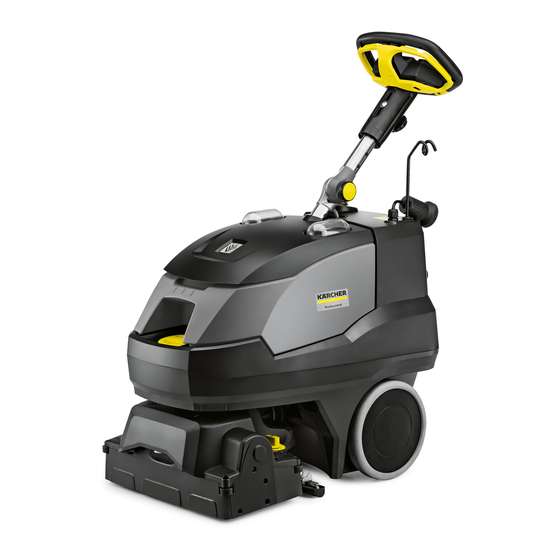
- Page 1 ARMADA BRC 40/22 C...
-
Page 2: Preface
Technical Support Specialists at 800-444-7654. Copying and duplication of texts and diagrams as well as third-party access to this information is permitted only with the explicit permission of the company: KARCHER NORTH AMERICA 4555 Airport Way Denver, CO 80239 Safety The BRC40/22 (Armada) uses 120VAC as a power source, proper precautions must be used to prevent electrocution. -
Page 3: Table Of Contents
Table of Contents PAGE # DESCIPTION PAGE # DESCIPTION Preface Machine operates, brush motor does not Safety Machine operates, the vac motor does not run Table of Contents Machine operates, pump does not run How the Machine Works Machine operates, deep extraction spry does not Technical specifications work Product overview... -
Page 4: How The Machine Works
How the machine works: The Armada is a 120 volt AC dual purpose carpet extractor intended for commercial use. This machine per- forms Interim maintenance cleaning as well as deep restorative extraction. The solution is applied during in- terim cleaning and agitated into the carpet fiber using a rotating cylindrical brush. The solution is not recov- ered but left to dwell on the carpet surface to be vacuumed up once the solution has completely dried to the touch (approximately 20 minutes). -
Page 5: Technical Specifications
Technical Specifications. -
Page 6: Product Overview
Product Overview... - Page 8 DEFINITIONS OF SELECTOR SWITCH 1. Brush only 2. Interim cleaning 3. Eco deep extraction 4. Deep extraction 5. Vacuum only 6. Accessory tool 7. Off When in mode 2 solution will come out of the center nozzle only When in mode 3 & 4 solution will come out of all 3 nozzles When in mode 1, 5 &...
-
Page 9: Tools Required
Tools required It is important for a technician to have all the appropriate tools available either in the field or in the shop. These tools include but are not limited to the list below. Standard and metric socket sets both 1/4” and 3/8” drives. ... - Page 10 Vacuum motor removal procedure Using a T-20 Torx driver remove the 4 screws holding the rear access panel onto the machine exposing the vacuum motor and electronics. Using a 1/4” ratchet with a 3/8 drive socket remove the 5 bolts holding the vacuum housing together, the 5th bolt is behind the housing on a raised stand-off.
- Page 11 Carefully work the motor out of the lower vacuum housing. Using the T-20 Torx driver remove the 3 screws holding the upper housing to the vacuum motor. Using a #2 Philips screw driver remove the 2 screws Inspect the lower vacuum housing and motor for evidence of holding the carbon brush cover on.
- Page 12 Vac motor carbon brush removal. Using a smell screw driver, push the tab on the brush holder to Once the pin is released you can remove the carbon release the pin. brush. 3/8” Inspect the carbon bush, once it reaches 3/8” in length replace the brush.
- Page 13 Pump removal procedure Remove the recovery tank from the machine exposing the To remove the pump push the gray ring in towards the elbow pump access cover. Using the T-20 Torx driver remove the 3 and pull on the hose at the same time releasing it from the screws holding the cover in place.
- Page 14 Before inserting the pump make sure that the harness to Once the pump is in place, connect the harness and the pump, pump harness and outlet hose are accessible. insert the hose into the pump outlet fitting. Insure hose is locked in place by pulling back on the hose. There should be little or no gap here, the pump is not properly installed.
- Page 15 Brush motor removal and disassembly process Rotate the head until the vac shoe hose is exposed. Remove Place the adjustment knob into position 1 and tip the machine the hose from the mount by pulling it toward you. on its back, note the position of the cam. Using a 10 mm sock- et on a 1/4”...
- Page 16 To access the screws holding the electrical cover and upper deck cover, you must remove the pump per the pump removal procedure starting on page 13. With the screw access holes in the bottom of the pump housing exposed, Rotate the head to align the screws. Using a T-25 Torx driver, remove the 4 screws.
- Page 17 The lower deck can be removed from the upper deck housing. To access the motor mount screws, the belt cover must be removed. Using a T20 Torx driver remove the 4 screws holding the cover on. Disconnect the brush motor and thermistor harnesses from Using a T20 Torx driver, remove the 4 screws holding the the main harness.
- Page 18 To remove the brush housing from the motor, remove the 4 screws holding the assembly together. Using a T-30 Torx to remove the 2 crews inside the housing then to 2 outside of the housing. Remove the coupler, the bearings are not replaceable. If the bearing in the gear case fail the entire gear case If you need to replace the gear box and must be replaced.
- Page 19 To remove and check the carbon brushes, use a flat screw driver to rotate the cap counter clockwise until it is out, then remove the brush. When the carbon brush wears to 3/8” inches it needs to be replaced. If it is allowed to wear further, damage to the motor commutator will occur.
- Page 20 Solenoid valve removal process In order to access the solenoids you must remove the lower deck as described in the brush motor removal section staring on page Most machines will have a finger guard over the solenoids. To With the finger guard released use a 3/8” wrench to remove the finger guard you will need the #20 Torx driver to remove the Ground wire from the guard.
- Page 21 Using the T-20 Torx Driver, remove the 2 screws holding the solenoid valve assembly to the upper deck cover. If you have determined that the valves are good and do not leak or are not stuck according to the solution system trouble- shooting section and discovered the coils are bad, it is easier to replace the coils than re-plumb the entire valve assembly.
- Page 22 Gently place the valve in a vice, using a 17mm Place the valve assembly into the upper brush deck taking care to align the open end wrench remove the fittings from the plastic tabs with the slots in the valve bracket and the holes for the screws. valve.
- Page 23 Steering column removal process Unlike the BR35/12 the bearing set that holds the steering column and deck pivot cannot be accessed by removing the recovery tank. The process below describes the most efficient way to access the bearing set. 5/8” 9/16 Rotate head to line up screws for removal.
- Page 24 Once the screws have been removed lower the head and shaft assembly to the table. Rotate the head assembley to orient the brass pin horizontally. Remove the 8 screws holding the steer- ing shaft to the tank.
- Page 25 Once the pin is horizontal use snap-ring pliers to remove the snap-ring, then push the pin out of the pivot joint. Collapse the two pieces of the remaining portion of the With the brass pin removed push the wrist pin out of the joint. bearing set into itself then remove.
- Page 26 Lift the rubber seal off of the deck pivot and work it up the wire harness to expose the snap ring. On machines built with the waterproof harness this seal is not present. Using a pair of snap-ring pliers, remove the snap-ring There is a ball bearing in the trough of the pivot, it is separating the pivot from the mount.
- Page 27 Using the Torx 20 driver, remove the two screws hold- Remove the screw holding the hose clamp on the black hose from the ing the solenoid mounting bracket to the upper deck. pump. Depress the outer ring push the hose into the fitting then pull it out.
- Page 28 Reverse these steps to reinstall the upper deck to the machine. There are three critical steps when attaching the upper deck that will require additional work if missed (see below). Place the pivot support onto the deck once it is seated the Make sure the ball bearing is placed back into the groove in snap ring groove will be visible.
- Page 29 Tower removal process Removal of the tower allows access to the solution tank cover/gasket, the strainer assembly and outlet hose from the tank to the strainer. The Steering shaft removal process needs to be performed in order to remove the tower assembly (see instructions on pages 23-28.
- Page 30 Remove the two screws in the back of the machine. Remove the pig tail neutral line from the switch and the black line wire from the breaker. Remove the ground wire from the ground stud on the control board panel. Remove the retaining nut on the strain relief for the handle harness.
- Page 31 Solution tank access Once the tower has been removed you have access to the tank cover, and the strainer. Old style New style If the solution cover has a metal plate holding part of the If this is the case you will need to upgrade to the new one piece cover it will leak water onto the deck if the tank is left full.
- Page 32 Control board removal process Using a T-20 Torx driver remove the rear panel as described on page 10. Caution: When handling control boards it is important to protect against electro static discharge. Always wear an anti ESD wrist strap grounded to the work bench. The control board contains two large capacitors that do not discharge when powered down, the control board comes with the mounting plate to prevent accidental shock.
- Page 33 To remove the power supply from the controller assembly squeeze the 4 standoffs to release them.
- Page 34 Miscellaneous repairs Glide wheel replacement The front glide wheels are an important part of the deck assembly, If they get jammed with debris they will wear prematurely causing the deck to dig into to the floor. To remove the glide wheel use a screwdriver to slide Pull the axel pin out with a pair of needle nose pliers and the axel pin out.
- Page 35 Spray shield and baffle plate replacement process To replace a damaged spray shied or brush motor baffle plate you will need to follow the procedure for removing the lower brush deck on pages 15-17. Using the T20 Torx driver to remove the spray shield from To remove the bush motor baffle plate you will need to remove the lower deck.
- Page 36 Jet body replacement You will need to separate the lower deck from the upper according to the process described on pages 15-17. To replace a jet body, remove the hose from the john guest fitting by pushing the green outer ring and holding it then push the hose in then pull it out. Remove the two screws holding the jet body in place.
- Page 37 Electrical Troubleshooting Explanation of technology The Armada controller is unique to the industry and uses several method to supply power to the electrical components. The Pic Duo controller uses a 12 Volt DC power supply to operate the logic of the board. It uses 120 VAC inputs to supply power to the components.
- Page 38 Electrical schematic...
- Page 39 Wire color code...
- Page 40 Skeletal view with electrical test points. This is the complete inner workings of an Armada the electrical test points are circles for identification...
- Page 41 Main control board. 12 v input from Input connector from power supply the handle assy. Input from selector Power supply to switch the fan Pickit programing port Power output for the brush motor Line input Vac motor line output 6 pin connector from the deck assembly Blue deep extraction sole- Line in.
- Page 42 12 volt power supply The 12 volt power supply provides power to the logics of the main controller. 120 VAC line input 2.5 amp fuse 12 volt output to main controller...
- Page 43 Solution system flow...
- Page 44 The machine is switched on but does not power up. With your volt meter set on AC voltage, check voltage at the wall outlet, is there 120+- VAC? (figure 1) Move to step 2. Check the wall breaker at the building’s electrical panel. With your volt meter set on AC voltage, check the line and neutral of the extension cord, is there 120 +- VAC? (figure 2) Move to step 3.
- Page 45 Figure 3 Figure 1 Figure 2 Figure 4 Figure 5 Figure 6 Figure 7 Figure 8 Machine powers up, nothing will operate. With your volt meter set on AC voltage, check for power o the accessory line input of the main controller, is there 120 VAC? (figure 1a) Replace main controller.
- Page 46 Machine powers up everything works except the brush motor, the brush light is solid red With your volt meter set on DC voltage, check for power at the brush motor connector on the main controller is there 135 +- VDC. (figure 1b) Go to step 2.
- Page 47 Machine powers up everything runs except the vac motor the icon is red. It is not possible to check for voltage to the vac motor if it is disconnected from the harness, the controller will put out 35 VAC. With your volt meter set on AC voltage, and the main switch in a vacuum mode, check for voltage at the vac motor connector in the harness, is the output 35 VAC? (figure 1c) Test the motor wires for resistance if greater than .3Ω...
- Page 48 Machine powers up everything runs except the pump will not run It is not possible to check for voltage to the vac motor if it is disconnected from the harness, the controller will only put out 21 VAC. Remove the pump cover as described on page 13. With your volt meter set on AC voltage, and the pump switch turned on with the main switch in a solution mode, pull the yellow hand lever and check for voltage at the connector in the harness, is there only 21 VAC? (figure 1d) Check the pump motor for resistance if it is greater than 12mΩ...
- Page 49 Machine powers up everything runs except the solution will only spray from the center jet in deep extraction Remove the 2 black jets from the machine, with the main switch in a deep extraction mode and the pump switch on press the yellow hand lever, does water flow from the jet bodies? Clean or replace the jets.
- Page 50 Machine powers up everything runs except the solution will not spray from the center jet in interim mode. Remove the 2 white jets from the machine, with the main switch in a deep extraction mode and the pump switch on press the yellow hand lever, does water flow from the jet body? Clean or replace the jet.
- Page 51 Error code trouble shooting Vacuum codes: Vacuum icon solid red—follow procedure on page 41 Vacuum light blinks 2X—vacuum motor is stalled, check motor for debris of rusty bearings. Vacuum light blinks 4X—Vacuum motor is running above specified current. Brush codes: Brush light blinks orange, continues to run—brush is running higher than specified current reduce brush pressure to 1 or 2 positions 3 and 4 are not necessary and will cause the motor to overheat.
- Page 52 Figure 1g Figure 2g...
- Page 53 Product enhancements In December 2016 starting with serial number 10080600000744 the vac shoe alignment plate was change to prevent binding and breakage of the vac shoe mounting bracket.
- Page 54 Steps to Prevent Water Intrusion in Armada Harness Connectors Required materials: Electrical tape, Dielectric grease (Permatex recommended), Scissors Wrap a piece of electrical tape around the “windows” on the sides of the 3-pin and 9-pin connectors. Fill the wire side of the taped 3-pin connector with dielectric grease, paying close attention to make sure the grease completely covers the a between the wires and connector.
- Page 55 Fill the cavity of the pin side of the 3-pin connector with dielectric grease until the grease is level with the end of the con- nector. Wrap the 3-pin connector and wires with electrical tape until the grease on the wire end is fully enclosed by the tape. Note: Tightly wrapping the tape around the wires to cinch them in to a bundle is recommended.
- Page 56 Fill the wire side of the taped 9-pin connector with dielectric grease, paying close attention to make sure the grease completely covers the area between the wires and connector. Fill the cavity of the pin side of the 9-pin connector with dielectric grease until the grease is level with the end of the connector.
- Page 60 New waterproof wiring harness Starting with s/n 10080600001129, a new waterproof wiring harness was introduced to prevent corrosion of the electrical con- nections and errant fault codes.
- Page 61 New material to strengthen the vac shoe mount...