Table of Contents
Advertisement
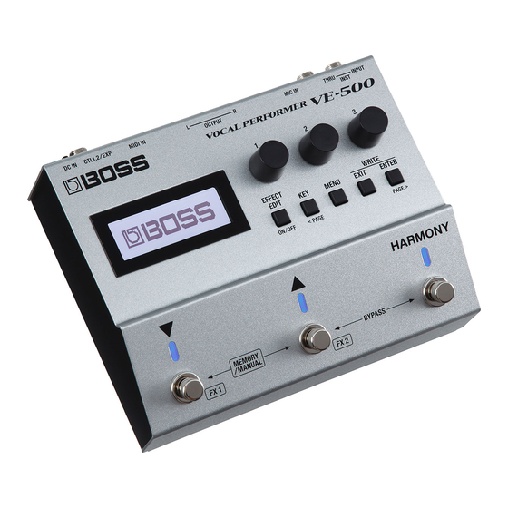
Owner's Manual
Main features
5 Provides numerous vocal effects for the guitarist
5 HARMONY automatically adds harmony to your vocal, based on your guitar playing
5 VOCODER uses your voice to add expressive power to your guitar performance
5 ENHANCE improves the clarity of your sound
5 PITCH CORRECT corrects inaccuracies in pitch
5 Four independent general-purpose FX units provide 20 distinctive effect types such as DISTORTION
and RADIO, and there are also two independent REVERB/DELAY units, giving you a high degree of
flexibility for making effect settings
5 Panel layout that provides high functionality and emphasizes live performance, with an easily
readable screen display and an independent [HARMONY] switch
5 Memory function lets you store and recall 99 setups in internal memory
5 By connecting a USB cable or MIDI cable, you can synchronize the unit with an external MIDI device
or a DAW on your computer, or switch sounds and control parameters
Owner's Manual
Read this first. It explains the basic things you need to know in order to use the VE-500. For detailed information
on how to operate the VE-500, please download and refer to "Parameter Guide" (PDF file).
PDF Manual
(download from the Web)
5 Parameter Guide
This explains all of the parameters of the
VE-500.
Before using this unit, carefully read "USING THE UNIT SAFELY" and "IMPORTANT NOTES" (the leaflet "USING THE
UNIT SAFELY" and the Owner's Manual (p. 20)). After reading, keep the document(s) where it will be available for
immediate reference.
© 2018 Roland Corporation
(this document)
1.
2.
To obtain the PDF manual
Enter the following URL on your
computer.
http://www.boss.info/manuals/
?
Choose "VE-500" as the product name.
Advertisement
Table of Contents

Related Manuals for Boss VE-500


Summary of Contents for Boss VE-500
- Page 1 Owner’s Manual (this document) Read this first. It explains the basic things you need to know in order to use the VE-500. For detailed information on how to operate the VE-500, please download and refer to “Parameter Guide” (PDF file).
-
Page 2: Table Of Contents
Contents Getting Ready System Settings (MENU) ........Connecting the Equipment . -
Page 3: Getting Ready
[GND LIFT] switch In some cases, you might hear “ground loop hum” (a buzz or hum) when the VE-500 is connected to an external device. If this occurs, changing the setting of the [GND LIFT] switch might lessen the problem. Normally you'll leave this switch in the NOR (NORMAL) position. -
Page 4: Connecting The Equipment
Getting Ready Connecting the Equipment CTL 1, 2 / EXP jack pin configuration TIP: 2: HOT RING: COLD SLEEVE: GND 3: CO CTL 1, 2/EXP jacks You can control various parameters by connecting a footswitch (FS-5U, FS-5L, FS-6, FS-7: sold separately) or an expression pedal (such as the FV-500H, FV-500L, EV-30, Roland EV-5: sold separately) to the CTL 1, 2/EXP jack (p. -
Page 5: Top Panel
Getting Ready Top Panel [EXIT] button Display This shows various information for the VE-500. Cancels an operation or returns to the previous screen. [1]–[3] knob [ENTER] ( [PAGE >] ) button Select and edit the parameter values shown in the display. -
Page 6: Screen Structure
Getting Ready Screen Structure System settings (p. 16) WRITE UTILITY screen (p. 14) Use the [< PAGE] Use the [1]–[3] knobs to move the cursor [PAGE >] buttons to change pages Use the [1]–[3] knobs to move the cursor MENU screen (p. 16) Play screen (p. -
Page 7: Operation Of The [1]-[3] Knobs
Getting Ready Operation of the [1]–[3] Knobs 5 In the play screen (p. 10), the [1]–[3] knobs 5 In the CTL & ASSIGN screen (p. 13), WRITE correspond to the functions that are assigned UTILITY screen (p. 15), and MENU screen by “System settings”... -
Page 8: Turning On/Off The Power
Getting Ready Turning On/Off the Power The DC IN jack also functions as the power switch. The power turns on when you insert the AC adaptor’s plug into the DC IN jack, and turns off when you disconnect it. * Before turning the unit on/off, always be sure to turn the volume down. Even with the volume turned down, you might hear some sound when switching the unit on/off. -
Page 9: Playing
In this mode you can recall and use patches that MIC SENS are saved in the VE-500’s memory. Use the [?] 0–200 (default: 100) and [=] switches to select a patch. Manual mode... -
Page 10: Switching Patches
Playing Switching Patches About the Play Screen The screen that appears after you turn on the Switch to memory mode. power is called the “Play screen. ” Use the [?] [=] switches to select a Press the [ENTER] button to switch the display. patch. -
Page 11: Editing A Patch
Editing a Patch Basic Operation Effect Explanation Improves the clarity of the sound. Recall the patch that you want to edit Corrects inaccuracies in pitch. This is (p. 10). available only when HRM (harmony) is selected. Press the [EFFECT EDIT] button. HRM: Adds harmony to your vocal. -
Page 12: Changing The Effect Connections
Editing a Patch In screens where page tabs are displayed, FX STRUCTURE use the [< PAGE] [PAGE >] buttons to move STRUCTURE1 between editing screen pages. LEAD Multi-FX HARMONY1 FX OUT1 HARMONY2 Use knobs [1]–[3] to specify the value of each parameter shown in the screen. -
Page 13: Changing The Ctl & Assign Settings
Editing a Patch Changing the CTL & ASSIGN Settings REVERB STRUCTURE STRUCTURE1 You can operate a variety of parameters by making CTL and ASSIGN settings for each patch. FX OUT1 Reverb In the effect select screen, use knobs FX OUT2 REV/DLY1 [1]–[3] to select “CTL,”... -
Page 14: Key Of The Song
Editing a Patch Controller Explanation Matching the Harmony to the Key of the Song ASSIGN allows you to make more detailed settings.For example, Press the [KEY] button. you can use ASSIGN if you want to simultaneously control another parameter in addition to operating the parameter of the [?] switch. -
Page 15: Saving A Patch (Write)
Editing a Patch * If you decide to cancel, press the [EXIT] button. Saving a Patch (Write) Once the patch has been saved, you arereturned to the Play screen. If you want to save the patch that you created, execute the Write operation. Exchanging Patches * You can use dedicated software to save, exchange, initialize, or back up patches (p. -
Page 16: System Settings (Menu)
System Settings (MENU) Settings that are shared by the entire VE-500 are Item Explanation called “system settings. ” Refer to “Restoring the Factory Default Settings (Factory Reset)” (p. 17). For details on the parameter, refer to the “Parameter Guide” (PDF file). -
Page 17: Adjusting The Display Contrast
Reset. ” Adjust the contrast with the [1] knob. Not only can you return all of the settings to the values in effect when the VE-500 was shipped from the factory, you can also specify the items to be reset. -
Page 18: Synchronizing With A Daw Or External Midi Device
EXP pedal. If the VE-500 is connected via USB to a computer, you For details on the parameter, refer to can also use dedicated software to do the following. -
Page 19: Appendix
Reduce the amount of MIDI data that is MIDI BUFFER FULL connected to the MIDI IN connector, and the being sent to the VE-500. VE-500 was unable to process it. The USB cable is connected. USB CONNECTED Communication from the connected device has been interrupted. -
Page 20: Using The Unit Safely
Co.,Ltd. eParts is a trademark of eSOL Co., Ltd. in Japan. • Before sending the unit away for repairs, • Roland and BOSS are either registered be sure to make a backup of the data trademarks or trademarks of Roland stored within it;...