Advertisement
Quick Links
Advertisement

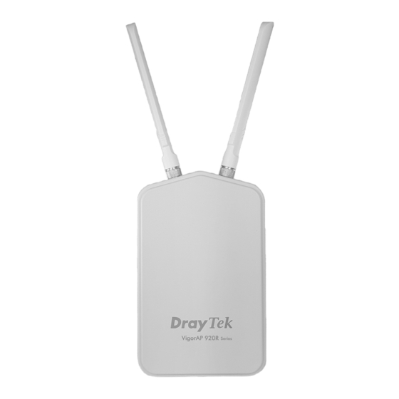
Summary of Contents for Draytek VigorAP 920R Series
-
Page 2: Quick Start Guide
Declaration of Conformity Hereby, DrayTek Corporation declares that the radio equipment type VigorAP 920R is in compliance with Directive 2014/53/EU The full text of the EU Declaration of Conformity is available at the following internet address: http://www.draytek.com.tw/ftp/ VigorAP 920R/Document/CE/... - Page 3 Please inspect the package contents. If anything is missing or damaged, please contact DrayTek or your dealer immediately. Main Unit Antennas Quick Start Guide Ethernet Cable (3M) Ground Cable Mount Kit Note Do not use Ethernet cables with molded hood boot.
- Page 4 Status Explanation The system is not ready or has failed. Blinking The system is ready. 2.4G / 5G / Wireless function is ready. Wireless function is not ready. Blinking Data is being transmitted (sending/receiving). 5G Signal (For D The signal strength (excellent) > -50dBm. Model) 5G Signal (For D The signal strength (good) is between -66dBm ~ -51dBm.
- Page 5 The VigorAP can be pole mounted depending on the installation environment. This section will guide you through installing the VigorAP. Note For the sake of personal safety, only trained and qualified personnel should install this access point. 1. Remove the protective cap. 2.
-
Page 6: C O N N E C T I N G E T H E R N E T C A B L E ( S )
Refer to the following steps to attach the Ethernet cable and waterproof head. (Take VigorAP 920RP as an example.) 1. Remove the cable cover for Ethernet Port (e.g., Port 1 PoE In). 2. Before connecting, verify that the cable has a rubber seal and that it is not damaged. - Page 7 1. Loosen the thread-lock sealing nut. 2. Loosen the clamping claw and seal. 3. Loosen the body and washer. 4. Remove the cable. 5. To reattach the cable, follow the above steps in reverse. Note The diameter for the Ethernet cable shall be limited between 4.3mm to 5.9mm.
- Page 8 – – 1. Find a suitable location for installing the access point. 2. Select a mounting point on a pole. 3. Remove the mounting plate from the mount kit by removing the four mounting screws. 4. Attach the VigorAP920 to the mounting plate. Lock the screws with torque of 20 kgf-cm.
- Page 9 5. Fasten the mount kit on the pole with nut screws and with torque of 20 kgf-cm. Note The diameter for a pole shall be limited between 35mm to 53mm. 6. Fasten the access point to the mount kit with screws (torque of 20 kgf-cm) as shown in the following figure.
- Page 10 In outdoor installations and before powering the access point with AC power, VigorAP must be grounded prior to wire installation. 1. Take out the ground cable from the mount kit. Ground Lug 2. Insert a ground rod on the ground. 3.
- Page 11 VigorAP 920R/RP can be powered via the PoE input from an in-line power injector or a suitably powered switch port. Before powering VigorAP, you should: Pay attention to local and national electrical codes. Not place the power injector / VigorSwitch in outdoor environment without any protection.
- Page 12 This section will guide you through the configuration of the settings using a web browser. 1. Make sure your PC is connected to access point correctly. 2. Open a web browser on your PC and type http://192.168.1.2. A pop-up window will open asking you for a username and password. Please type “admin/admin”...
- Page 13 3. The Main Screen will be displayed. Click Quick Start Wizard. 4. This page shows operation modes of the wireless LANs (2.4GHz/5GHz), and whether or not they are enabled. You may alter the settings if you wish.
- Page 14 5. The subsequent page is for configuring the 2.4G wireless connection. Select one of the five operation modes. The following figure shows the configuration page for the AP (Access Point) operation mode. Configuration pages for other operation modes will differ. In this example, choose AP and click Next to configure the following page.
- Page 15 7. When you have completed making changes to settings for wireless LAN (5GHz), click Next. The following final page will be shown. If you are satisfied with the changes you have made, click Finish. You may verify your settings by navigating to Online Status on the Main Screen. Note Under System Maintenance, you can change the access point’s default admin password.
-
Page 16: Contacting Draytek
20 centimeters between the radiator and your body. GPL Notice This DrayTek product uses software partially or completely licensed under the terms of the GNU GENERAL PUBLIC LICENSE. The author of the software does not provide any warranty.


