Pilz PZE X4V Operating Manual
Safety relays
Hide thumbs
Also See for PZE X4V:
- Operating instructions manual (16 pages) ,
- Operating instructions manual (12 pages) ,
- Operating manual (23 pages)
Table of Contents
Advertisement
Advertisement
Table of Contents

Related Manuals for Pilz PZE X4V


Summary of Contents for Pilz PZE X4V
- Page 1 PZE X4V Safety relays Operating Manual 1003200-EN-09...
- Page 2 Preface This document is a translation of the original document. All rights to this documentation are reserved by Pilz GmbH & Co. KG. Copies may be made for internal purposes. Suggestions and comments for improving this documentation will be gratefully received.
-
Page 3: Table Of Contents
Block diagram/terminal configuration Function description Installation Wiring Preparing for operation Operation Status indicators Faults – Interference Dimensions in mm Technical details Safety characteristic data Supplementary data Service life graph Order reference EC declaration of conformity Operating Manual PZE X4V 1003200-EN-09... -
Page 4: Introduction
This describes a situation in which the product or devices could be dam- aged and also provides information on preventive measures that can be taken. It also highlights areas within the text that are of particular import- ance. Operating Manual PZE X4V 1003200-EN-09... -
Page 5: Safety
In order to achieve the re- quired safety level for the overall plant/machine, define the safety requirements for the plant/machine and then define how these must be implemented from a technical and organ- isational standpoint. Operating Manual PZE X4V 1003200-EN-09... -
Page 6: Use Of Qualified Personnel
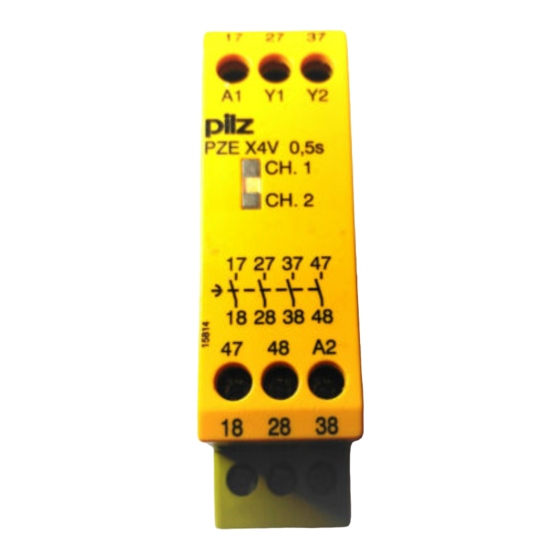
250 V. Unit features Positive-guided relay outputs: – 4 safety contacts (N/O), delay-on de-energisation LED display for: – Switch status of the safety contacts Connection for feedback loop Operation: single-channel Unit types with various delay times Operating Manual PZE X4V 1003200-EN-09... -
Page 7: Safety Features
Functional procedure once the input circuit is closed (e.g. safety contacts on the base unit are closed): – The supply voltage is present at input (A1) of the contact expansion module. – The safety contacts 17-18, 27-28, 37-38 and 47-48 close. – The LEDs "CH.1" and "CH.2" illuminate. Operating Manual PZE X4V 1003200-EN-09... -
Page 8: Installation
Ensure the EMC requirements of IEC 60204-1 are met. The power supply must comply with the regulations for extra low voltages with protect- ive electrical separation (SELV, PELV) in accordance with VDE 0100, Part 410. Operating Manual PZE X4V 1003200-EN-09... -
Page 9: Preparing For Operation
The safety functions may only be checked by qualified personnel. Status indicators LEDs indicate the status and errors during operation: LED on CH.1 Safety contacts of channel 1 are closed. CH.2 Safety contacts of channel 2 are closed. Operating Manual PZE X4V 1003200-EN-09... -
Page 10: Faults - Interference
-15 %/+10 % -15 %/+10 % Output of external power supply (DC) 2,5 W 2,5 W 2,5 W Residual ripple DC 20 % 20 % 20 % Duty cycle 100 % 100 % 100 % Operating Manual PZE X4V 1003200-EN-09... - Page 11 EN 60947-5-1 EN 60947-5-1 EN 60947-5-1 Utilisation category of safety contacts delayed AC15 at 230 V 230 V 230 V Max. current DC13 (6 cycles/min) at 24 V 24 V 24 V Max. current Operating Manual PZE X4V 1003200-EN-09...
- Page 12 0,5 s Time accuracy -50 %/+50 % -50 %/+50 % -50 %/+50 % Supply interruption before de-energisation 250 ms 500 ms 1.000 ms Environmental data 774580 774581 774582 Climatic suitability EN 60068-2-78 EN 60068-2-78 EN 60068-2-78 Operating Manual PZE X4V 1003200-EN-09...
- Page 13 ABS UL 94 V0 ABS UL 94 V0 ABS UL 94 V0 PPO UL 94 V0 PPO UL 94 V0 PPO UL 94 V0 Connection type Screw terminal Screw terminal Screw terminal Mounting type Fixed Fixed Fixed Operating Manual PZE X4V 1003200-EN-09...
- Page 14 Current pulse, A1 1,7 A 1,7 A Pulse duration, A1 50 ms 180 ms Inputs 774586 774583 Number Voltage at Input circuit DC 24 V 24 V Current at Input circuit DC 95 mA 95 mA Operating Manual PZE X4V 1003200-EN-09...
- Page 15 Max. melting integral 66 A²s 66 A²s Blow-out fuse, quick Blow-out fuse, slow Blow-out fuse, gG Circuit breaker 24 V AC/DC, characteristic B/C Contact material AgCuNi + 0,2 µm Au AgCuNi + 0,2 µm Au Operating Manual PZE X4V 1003200-EN-09...
- Page 16 III / II Pollution degree Rated insulation voltage 250 V 250 V Rated impulse withstand voltage 4 kV 4 kV Protection type Mounting area (e.g. control cab- inet) IP54 IP54 Housing IP40 IP40 Terminals IP20 IP20 Operating Manual PZE X4V 1003200-EN-09...
-
Page 17: Safety Characteristic Data
[1/h] 2008 2008 2008 Category [year] – PL d Cat. 3 SIL CL 2 2,48E-09 SIL 2 1,47E-05 All the units used within a safety function must be considered when calculating the safety characteristic data. Operating Manual PZE X4V 1003200-EN-09... -
Page 18: Supplementary Data
The service life graphs indicate the number of cycles from which failures due to wear must be expected. The wear is mainly caused by the electrical load; the mechanical load is negli- gible. Switching current (A) Fig.: Service life graphs at 24 VDC and 230 VAC Operating Manual PZE X4V 1003200-EN-09... -
Page 19: Order Reference
PZE X4V 24 V DC; t = 1 s Screw terminals 774581 PZE X4V 24 V DC; t = 2 s Screw terminals 774582 PZE X4V 24 V DC; t = 3 s Screw terminals 774583 Operating Manual PZE X4V 1003200-EN-09... -
Page 20: Ec Declaration Of Conformity
European Parliament and of the Council. The complete EC Declaration of Conformity is available on the Internet at www.pilz.com/support/downloads. Representative: Norbert Fröhlich, Pilz GmbH & Co. KG, Felix-Wankel-Str. 2, 73760 Ost- fildern, Germany Operating Manual PZE X4V... - Page 21 Back cover Support Technical support is available from Pilz round the clock. Americas Australia Scandinavia Brazil +61 3 95446300 +45 74436332 +55 11 97569-2804 Spain Canada Europe +34 938497433 +1 888-315-PILZ (315-7459) Austria Switzerland Mexico +43 1 7986263-0 +41 62 88979-30...