Advertisement
Quick Links
Installation and Operating Instructions
SAFETY CONSIDERATIONS
Read and follow manufacturer instructions carefully.
Follow all local electrical codes during installation. All wiring
must conform to local and national electrical codes. Improper
wiring or installation may damage thermostat.
Understand the signal words — DANGER, WARNING,
and CAUTION. DANGER identifies the most serious hazards,
which will result in severe personal injury or death.
WARNING signifies hazards that could result in personal
injury or death. CAUTION is used to identify unsafe practices,
which would result in minor personal injury or product and
property damage.
Recognize safety information. This is the safety-alert
symbol (
). When this symbol is displayed on the unit and in
instructions or manuals, be alert to the potential for personal
injury. Installing, starting up, and servicing equipment can be
hazardous due to system pressure, electrical components, and
equipment location.
GENERAL
The 24V Interface for the VRF (Variable Refrigerant Flow)
system is a device that enables the use of a conventional
24VAC thermostat with indoor units. The Interface receives
24VAC signals for Cool, Heat, and Fan; translates these
commands to the system's communication protocol; and sends
the commands to indoor unit over the HA / HB communication
bus.
The 24V Interface accessory is available for use with the
VRF (variable refrigerant flow) system indoor units listed in
Table 1.
Table 1 — 24V Interface Accessory Usage
UNIT
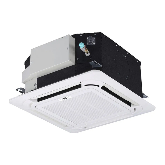
40VMC Compact Cassette
40VMF 4-Way Cassette
40VMH High Static Ducted
40VML Low Static Ducted
40VMM Medium Static Ducted
40VMR Floor Console -
Recessed
40VMU Under Ceiling/Floor
40VMV Vertical AHU
40VMW High Wall
Manufacturer reserves the right to discontinue, or change at any time, specifications or designs without notice and without incurring obligations.
Catalog No. 17-40VM900008-01
Part Number 40VM900008
SIZES
007,009,012,015
009,012,015,018,024,030,036,
048
024,030,036,048, 054, 072, 096
007, 009, 012, 015, 018, 024
007,009,012,015,018,024, 030,
036, 048
007, 009, 012, 015, 018, 024
012,018,024,030,036,048
018,024,030,036,048, 054
007,009,012,015,018, 024, 030
Printed in USA
Form 40VM-7SI
40VM Series Indoor Fan Coils
VRF (Variable Refrigerant Flow) System
24V Interface Accessory
WIRING REQUIREMENTS
24V Interface shall be configured for use with a conventional
24VAC thermostat with outputs for Fan, Heat, and Cool.
1. Wiring for Fan, Heat, and Cool signals from
Thermostat to interface should be performed with 18
AWG thermostat wire.
2. Terminals on 24V interface support 24VAC (+10%)
signal only.
3. Communication wiring from 24V Interface to Indoor
Unit (HA/HB) should be 20-16 AWG, stranded, shielded
control wire.
INSTALLATION
To install the 24V Interface:
1. Turn off all power to the indoor unit; turn off all power to
field-supplied 24VAC transformer serving the thermostat.
Electrical shock can cause personal injury and death.
Before installing thermostat, shut off all power to this
equipment during installation. There may be more than one
power disconnect. Tag all disconnect locations to alert
others not to restore power until work is completed.
2. If an existing thermostat is being replaced:
a. Remove existing thermostat from wall or unit.
b. Disconnect wires from existing thermostat. Do not
allow wires to fall back into the wall or unit.
c. Discard or recycle old thermostat.
Failure to follow this caution may result in equipment
damage or improper operation.
Improper wiring or installation may damage the
thermostat. Check to make sure wiring sequence is correct
at both ends before proceeding with installation or turning
on unit.
3. Select an appropriate location to install the 24V
Interface—for example, inside a 4"x4" junction box.
Coordinate with local electrical codes.
4. Connect HA HB terminals of 24V Interface to the HA
HB terminal of the indoor unit control board using
stranded, shielded control wiring.
NOTE: The thermostat and 24VAC power are field provided.
Pg 1
WARNING
CAUTION
02-17
Replaces: New
Advertisement

Related Manuals for Carrier 40VMC


Summary of Contents for Carrier 40VMC
- Page 1 Table 1 — 24V Interface Accessory Usage Failure to follow this caution may result in equipment damage or improper operation. UNIT SIZES 40VMC Compact Cassette 007,009,012,015 Improper wiring or installation may damage the 009,012,015,018,024,030,036, thermostat. Check to make sure wiring sequence is correct...
- Page 2 8. The indoor unit will limit the temperature range set point based on the indoor unit’s specifications. 7. Configure the third-party thermostat per manufacturer’s 9. The 24V Interface does not support Carrier VRF ERV instructions. If third-party thermostat has adjustable Interface.