
Related Manuals for Thunder TDR15100

Summary of Contents for Thunder TDR15100
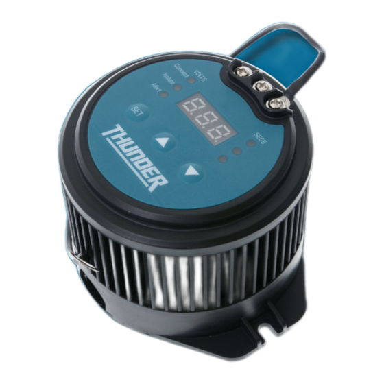
- Page 1 CONGRATULATIONS ON YOUR PURCHASE OF YOUR THUNDER ELECTRONIC BATTERY ISOLATOR For your personal safety please read, understand and follow the information provided in this instruction manual.
-
Page 2: Table Of Contents
CONTENTS Specifications and Recommendations Installation Settings Operation Reverse Charging System Contents Copyright © 2016 GPC Asia Pacific Pty Ltd ABN 97 097 993 283... -
Page 3: Specifications And Recommendations
SPECIFCATIONS AND RECOMMENDATIONS SPECIFICATIONS 9.2-16.0 Volts 100 Amps CONNECT VOLTAGE MAXIMUM CONTINUOUS CURRENT 9.0-15.8 Volts 400 Amps ISOLATE VOLTAGE MAXIMUM INRUSH CURRENT 9.0-15.6 Volts 0.04 Amps VISUAL ALARM VOLTAGE STANDBY CURRENT 1-255 seconds 80°C DELAY MAXIMUM TEMPERATURE 100mm 110mm(L) x 90mm(W) x 72mm(H) MOUNT (C-C) DIMENSIONS CABLE AND FUSE RECOMMENDATIONS... -
Page 4: Installation
INSTALLATION Ensure auxiliary battery negative post is properly grounded to vehicle. Use the screws on the top of the battery isolator to connect to: Using the appropriate cable and fuse/circuit breaker, connect the terminal (i) Connect the terminal marked 'NEG' to earth with the supplied black cable. marked 'main' to the positive terminal of the main or starting battery. -
Page 5: Settings
SETTINGS There are no correct or incorrect settings for the battery isolator, the set points are Repeat from installation step 2 to continue to adjust all set points. entirely dependent on the user and the required end result. The main objectives are There are six (6) items that need to be set: to protect your main cranking battery from being overly discharged (disengaging at a reasonable voltage) and, under extreme circumstances being able to utilise... -
Page 6: Operation
OPERATION Once your battery isolator is installed and the set points are programmed it is operational at all times. All functions can be visually checked by either the remote indicator or the LED readout on the unit. DISPLAY REMOTE DESCRIPTION Main battery is connected to the main stud (only occurs when connecting the battery isolator to the vehicle). -
Page 7: Reverse Charging System
REVERSE CHARGING SYSTEM In a number of situations, the auxiliary battery may need to be connected to a solar input or additional charging system. The battery isolator will recognise that the auxiliary battery is receiving charge and if the main battery is below 12.8 volts and the auxiliary battery is above 13.36 volts and receiving a charge, the battery isolator will open the circuit and allow the auxiliary battery to charge the main battery. - Page 8 GPC Asia Pacific Pty Ltd ABN 97 097 993 283 51-57 Qantas Drive Brisbane Airport QLD 4007 AUSTRALIA thunderauto.com.au // thunderauto.co.nz...