Table of Contents
Advertisement
Quick Links
SERIOUS INJURY OR DEATH COULD
RESULT FROM THE IMPROPER RE-
PAIR OR SERVICE OF THIS TOOL.
REPAIRS AND / OR SERVICE TO THIS
TOOL MUST ONLY BE DONE BY AN
AUTHORIZED AND CERTIFIED
DEALER.
Copyright © 1999 The Stanley Works
Copyright © 1999 The Stanley W
Copyright © 1999 The Stanley W
Copyright © 1999 The Stanley W
Copyright © 1999 The Stanley W
OPS/MAINT USA VERSION
05449 03/99 Ver 2
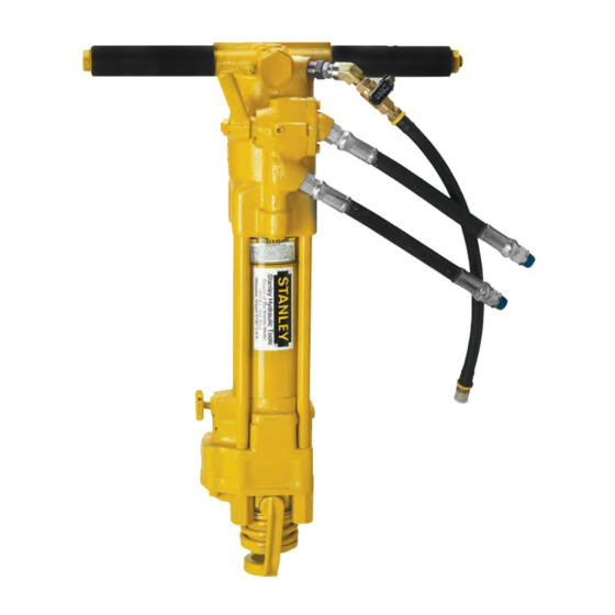
Hydraulic Sinker Drill
orks
orks
orks
orks
Safety, Operation and Maintenance
Safety
Safety
, Operation and Maintenance
, Operation and Maintenance
, Operation and Maintenance
Safety
Safety
, Operation and Maintenance
Service Manual
Service Manual
Service Manual
Service Manual
Service Manual
Stanley Hydraulic T
Stanley Hydraulic T
Stanley Hydraulic Tools
Stanley Hydraulic T
Stanley Hydraulic T
3810 SE Naef Road
Milwaukie, OR 97267-5698 USA
Phone: (503) 659-5660
Fax: (503) 652-1780
SK58
ools
ools
ools
ools
Advertisement
Table of Contents

Related Manuals for Stanley SK58


Summary of Contents for Stanley SK58
- Page 1 Stanley Hydraulic T Stanley Hydraulic Tools Stanley Hydraulic T ools ools 3810 SE Naef Road Copyright © 1999 The Stanley W Copyright © 1999 The Stanley Works Copyright © 1999 The Stanley W orks orks orks Copyright © 1999 The Stanley W Copyright ©...
- Page 2 COPYRIGHT© 1999 The Stanley Works. All rights reserved. Under copyright law, this document may not be copied in whole or in part without the prior written consent of The Stanley Works. This excep- tion does not permit copies to be made for others, whether or not sold.
-
Page 3: Table Of Contents
BE DONE B BE DONE BY AN A Y AN A Y AN AUTHORIZED AND CERTIFIED DEALER UTHORIZED AND CERTIFIED DEALER For the nearest authorized and certified dealer, call Stanley Hydraulic Tools at 1-503-659-5660 and ask for a Customer Service Representative. -
Page 4: Safety Precautions
SAFETY The SK58 Hydraulic Sinker Drill will provide safe and dependable service if operated in accordance with the instructions given in this manual. Read and understand this manual and any stickers and tags attached to the tool and hoses before operation. Failure to do so could result in personal injury or equipment damage. - Page 5 SAFETY Continued . . . • Always replace parts with replacement parts recommended by Stanley Hydraulic Tools. • Check fastener tightness often and before each use daily. SAFETY SYMBOLS Safety symbols are used to emphasize all operator, maintenance and repair actions which, if not strictly followed, could result in a life-threatening situation, bodily injury or damage to equipment.
-
Page 6: Tool Stickers And Tags
USE ONLY PARTS AND REPAIR USE ONLY PARTS AND REPAIR PROCEDURES APPROVED BY PROCEDURES APPROVED BY STANLEY AND DESCRIBED IN THE STANLEY AND DESCRIBED IN THE OPERATION MANUAL. OPERATION MANUAL. TAG TO BE REMOVED ONLY BY TAG TO BE REMOVED ONLY BY TOOL OPERATOR. -
Page 7: Hydraulic Hose Requirements
HOSE SAFETY T HOSE SAFETY T To help ensure your safety, the following DANGER tags are attached to all hose purchased from Stanley Hydraulic Tools. DO NOT REMOVE THESE TAGS. If the information on a tag is illegible because of wear or damage, replace the tag immediately. A new tag may be obtained at no charge from your Stanley Distributor. -
Page 8: Hydraulic Requirements
T3.20,15/EHTMA specifications. micron filtration. Stanley recommends using filter PRINCIPLE OF OPERATION The SK58 Sinker Drill is designed to be used to drill factor for the particular application. Incorrect rotation holes in rock such as blast holes. speed and/or inadequate extraction of the rock cuttings... - Page 9 OPERATING INSTRUCTIONS 1. Thread a rock bit onto the drill steel. PREOPERATION PROCEDURES 2. Rotate the latch (61) out and up. Preparation For Initial Use 3. Slide the drill steel into the tool. The tool, as shipped, has no special unpacking or 4.
-
Page 10: Operation
2. Start the hydraulic supply and turn the circuit COLD WEATHER OPERATION control valve to the "ON" position. If the tool is to be used during cold weather, preheat the 3. Open the air valve on the tool just enough to permit hydraulic fluid at low engine speed. -
Page 11: Service Instructions
(42) out of the accumulator housing toward the inlet flange side. Remove the o-ring (38) and kap seal (37), washer (39), kap seal (40) and o-ring 1. Obtain Stanley special tools latch removal tool (p/n (41). 05045) and latch installation tool (p/n 05062). -
Page 12: Hydraulic Motor Service
9. If it is necessary to remove the bushings (70 & 71), accumulator housing with the key way facing obtain the following Stanley special tools. upward toward the handles on the accumulator housing. - Page 13 bushing bores are yellow-bronze, replace them and 4. Install the woodruff key (77) into the slot in the investigate the cause of wear. drive hex. The flat surfaces around the chamber and bolt holes 5. Lubricate the idler gear (72) and drive gear (99) should be flat and free of nicks or burrs that could cause with clean hydraulic fluid and then install them into misalignment or leaks.
-
Page 14: Accumulator Housing , Accumulator, Flow Sleeve, Piston, And Automatice Valve Service
4. Remove the charge valve. a. Place the Stanley special split ring tool (p/n 5. Remove the blower tube nut (43). 04908) on top of the Stanley special flow sleeve removal tool (p/n 04910). - Page 15 (23) from the accumulator cylinder, matic valve body (56) and piston (29) is by using an place the accumulator assembly on Stanley special assembly fixture such as that shown in figure 1. The disassembly tools (p/n 05508 ring and p/n 04910 fixture permits the parts to be stacked vertically during tube).
- Page 16 2. Apply grease and install an o-ring (21) onto the flow 11. Install the accumulator assembly over the stem of sleeve tube. the piston and down to the top of the automatic valve body. 3. Apply clean hydraulic fluid and install 4 push pins (58) into the holes in the top of the flow sleeve tube.
-
Page 17: Accumulator Charging
Remove the tester from the charge valve. 2. Holding the chuck end of the Stanley tester (p/n 02835), turn the gauge fully counterclockwise to 9. On charge valves containing 5/8 inch hex locking ensure the stem inside the chuck is completely nuts, tighten the locking nut. -
Page 18: Troubleshooting
TROUBLE SHOOTING in the table. Use a flowmeter known to be accurate. If symptoms of poor performance develop, the follow- Check the flow with the hydraulic oil temperature at ing chart can be used as a guide to correct the problem. least 80°F/27°C. - Page 19 PROBLEM CAUSE SOLUTION Tool operates slow Low gpm supply from power unit. Check power unit for proper flow (7-9 gpm) High backpressure. Check hydraulic system for excessive backpressure (over 250 psi). Couplers or hoses blocked. Remove obstruction. Orifice plug blocked. Remove restriction.
-
Page 20: Accessories
SPECIFICATIONS Pressure Range ............................1500-2000 psi/104-140 bar Shank Size (SK58110 (Air) ,SK58120 (Water) , & SK58310 UW (Air) ................ 4-1/4 in. x 1 in. hex Shank Size (SK58130(Air ) ..........................4-1/4 in. x 7/8 in. hex Maximum Back Pressure ..............................250 psi/17 bar Flow Range ................................ -
Page 21: Parts Lists
PARTS LIST Item Part Item Part Description Description 04066 AUTOMATIC VALVE BODY 04763 AIR TUBE (SK58110, SK58 130 & 04571 PUSH PIN SK58310 MODELS ONLY) 04067 PUSH PIN 04965 WATER TUBE (SK58120 MODEL 03786 GPM STICKER 7-9 2000P ONLY) 05152... -
Page 22: Model Descriptions
SK58 SINKER DRILL MODELS SK58110, SK58120, SK58130, & SK58310 March 1999... -
Page 23: Parts Illustration For Anti-Vibration Handle Models
Stanley Hydraulic Tools (hereinafter called “Stanley”), subject to the exceptions contained below, warrants new hydraulic tools for a period of one year from the date of sale to the first retail purchaser, or for a period of 2 years from the shipping date from Stanley, whichever period expires first, to be free of defects in material and/or workmanship at the time of delivery, and will, at its option, repair or replace any tool or part of a tool, or new part, which is found upon examination by a Stanley authorized service outlet or by Stanley’s factory in Milwaukie, Oregon to be DEFECTIVE IN MATERIAL AND/OR... - Page 24 Stanley Hydraulic Tools • 3810 S.E. Naef Road • Milwaukie, Oregon 97267-5698 Phone: 503/659-5660 • Fax: 503/652-1780...