Advertisement
Advertisement
Table of Contents

Related Manuals for Heathkit HD-1410

Summary of Contents for Heathkit HD-1410
- Page 1 HEATHKIT HD-1410 ELECTRONIC KEYER...
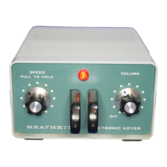
- Page 2 INTRODUCTION The HD-1410 is a compact Electronic Keyer with a built in AC power supply, mechanical paddles, sidetone oscillator and speaker in one package. It is designed and styled to complement the "SB" Series and is compatible with virtually all modern transmitters and transceivers, as well as most older rigs.
-
Page 3: Operation
OPERATION The HD-1410 Electronic Keyer is an iambic or "squeeze" keyer. As such, this Keyer has two inde- pendent paddles, one for dots and one for dashes. While you can treat the paddles as a single paddle without learning iambic operation, less effort is required to form many characters once you learn the iambic method. -
Page 4: Specifications
SPECIFICATIONS KEYING Speed Variable from less than 10 to over 60 words per minute. (alternate connection for less than 10 to over 35 words per minute.) Keyer Output Positive line to ground: Max. voltage, open circuit or spikes – 300 V, max. current – 200 mA. Negative line to ground: Max. -
Page 5: Circuit Description
CIRCUIT DESCRIPTION Refer to the Schematic Diagram and the Block Diagram while you read the following description. To help you locate parts in the Keyer or on the Schematic, the resistors, capacitors and other com- ponents are numbered in the following groups: 1 –... -
Page 6: Reset Circuitry
NEXT-BIT MEMORIES (NBM) There are two "next-bit memories;" one for dots, composed of gates IC1A and IC2A and one for dashes, composed of gates IC1B and IC2B. Each pair of gates is cross-coupled to form an R-S (set-reset) flip-flop. Since their operation is similar, only the dash NBM will be discussed. Figure 10 When no bit is being sent, 1C2 pin 8 is high since the clock is tow. -
Page 7: Output Circuitry
The leading edge of this clock pulse takes IC2 pin 11 low. This will reset the dot NBM unless the dot paddle is still closed. If the dash paddle has not been closed, then there is a low on IC3 pin 4 which holds IC3 pin 6 high, and the PBM cannot change state. -
Page 8: Block Diagram
BLOCK DIAGRAM... -
Page 9: Circuit Board X-Ray View
CIRCUIT BOARD X-RAY VIEW NOTE: To find the PART NUMBER of a component for the purpose of ordering a replacement: A. Find the circuit component number (R15, C3 etc.) on the X-Ray View or "Chassis Photograph". B. Locate this same number in the "Circuit Component Number" column of the "Parts List". C. - Page 10 (Viewed from component side)
- Page 11 CIRCUIT BOARD VOLTAGE CHART (Viewed from foil side)
-
Page 12: Chassis Photograph
CHASSIS PHOTOGRAPH MOD FROM "HINTS AND KINKS" TO CHANGE RANGE TO 8-35 WPM AND MAKE SPEED CONTROL LESS CRITICAL: PLACED 5k6 IN SERIES WITH R9; SHUNT SPEED CONTROL WITH 33k.