Table of Contents
Advertisement
AIR CONDITIONER
REMOTE CONTROLLER
(WIRED TYPE)
UTY-RNNUM
INSTALLATION MANUAL
For authorized service personnel only.
Contents
1. SAFETY PRECAUTIONS ............................................. 2
2. ACCESSORIES ............................................................ 2
3. ELECTRICAL REQUIREMENT ..................................... 2
4. SELECTING AN INSTALLATION LOCATION ............... 3
4.1. Dimensions ............................................................ 3
4.2. Name of parts ......................................................... 3
5. INSTALLING THE REMOTE CONTROLLER ............... 4
5.1. Installation .................................................................4
5.2. Setting the DIP switch ............................................ 4
5.3. Connection of remote controller cable ................... 5
6. INSTALLATION METHODS .......................................... 5
6.1. Group control ......................................................... 5
6.2. Dual remote control ............................................... 6
7. TURNING ON THE POWER ......................................... 6
LOCATION .......................................................................6
9. FUNCTION SETTING ................................................... 7
10. TEST OPERATION ....................................................... 9
11. ERROR CODES ........................................................... 9
PART NO. 9373328148-02
Advertisement
Table of Contents

Related Manuals for Fujitsu UTY-RNNUM


Summary of Contents for Fujitsu UTY-RNNUM
-
Page 1: Table Of Contents
AIR CONDITIONER REMOTE CONTROLLER (WIRED TYPE) UTY-RNNUM INSTALLATION MANUAL For authorized service personnel only. Contents 1. SAFETY PRECAUTIONS ..........2 2. ACCESSORIES ............2 3. ELECTRICAL REQUIREMENT ........2 4. SELECTING AN INSTALLATION LOCATION ....3 4.1. Dimensions ............3 4.2. -
Page 2: Safety Precautions
1. SAFETY PRECAUTIONS 2. ACCESSORIES The following installation parts are supplied. Use them as • Let the customer keep this installation manual because it required. is needed when the air conditioner or remote controller is serviced or moved. Name and Shape Q’ty Application Installation manual... -
Page 3: Selecting An Installation Location
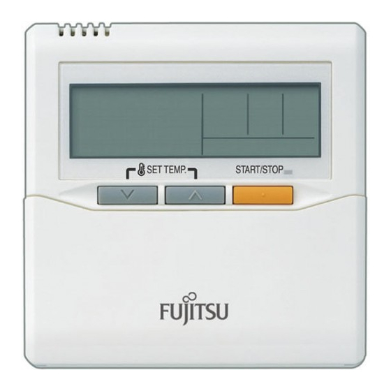
4.2. Name of parts 4. SELECTING AN INSTALLATION LOCATION ● With cover open 4.1. Dimensions Display panel 4-3/4 (120) 23/32 (18) ● Display panel 1-3/16 1-5/16 (30) (33.5) 24 25 Hole 29/32 1 “ ”, “ ” (Set Temperature (23) Button) 2 “... -
Page 4: Installing The Remote Controller
5. INSTALLING THE REMOTE 5.2. Setting the DIP switch CONTROLLER CAUTION 1 Install the remote controller wires so as not to be direct 5.1. Installation touched with your hand. 5.1.1. Installing the remote controller 2 Do not touch the remote controller PC board and PC Open the operation panel on the front of the remote controller, board parts directly with your hands. -
Page 5: Connection Of Remote Controller Cable
5.3.2. When connecting to the exclusive terminal 5.3. Connection of remote controller cable block CAUTION Connect the end of remote controller cable directly to the exclusive terminal block. • When connecting the remote controller cable to the wall mounted type indoor unit, do not connect it to the outdoor M4 screw unit or the indoor unit power terminal block. -
Page 6: Dual Remote Control
6.2. Dual remote control 8. SETTING THE ROOM TEMPERATURE DETECTION LOCATION • Depending on the model, some indoor units cannot be connected for dual remote controllers. (Option is not • The detection location of the room temperature can be available for U.S.A. wall mounted type indoor unit.) selected from the following 2 examples. -
Page 7: Function Setting
NOTES (6) Repeat steps 2 to 5 to perform additional settings. Press the “ ” button, “ ” button If the function to change the temperature sensor is used as and “ ” simultaneously again for more than 5 seconds shown in example A (other than example B), be sure to lock to cancel the function setting mode. - Page 8 2) Ceiling height 7) Auto restart Select the setting values in the table below according to the Enable or disable automatic system restart after a power outage. height of the ceiling. (♦... Factory setting) (♦... Factory setting) Function Setting Setting Description Number Value Function...
-
Page 9: Test Operation
11) Room temperature control switching 11. ERROR CODES (Only for Wired remote controller) This setting is used to set the room temperature control If you use a wired type remote control, error codes will appear on the remote control display. If you use a wireless remote method when the wired remote controller is selected by the control, the lamp on the IR receiver unit will output error codes Indoor Room Temperature Sensor Switching Function. - Page 10 Compressor Refriger- Outdoor Inverter PCB (10) temperature unit ant system error error Pressure Refriger- Outdoor Active filter (10) error 2 ant system error, unit Outdoor IPM error Unit flow Branch unit (13) divider error Outdoor Display panel Display mode : 0.5s ON / 0.5s OFF (10) unit error...