Advertisement
Quick Links
INSTALLATION AND
SERVICING
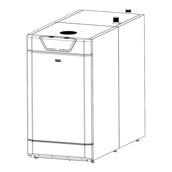
IMAX XTRA EL
320-620kW
When replacing any part on this appliance, use only spare parts that you can be assured conform to the safety and performance
specification that we require. Do not use reconditioned or copy parts that have not been clearly authorised by Ideal.
For the very latest copy of literature for specification and maintenance practices visit our website www.idealcommercialboilers.com
where you can download the relevant information in PDF format.
June 2018
UIN 212631 A06
Advertisement

Related Manuals for IDEAL IMAX XTRA EL


Summary of Contents for IDEAL IMAX XTRA EL
- Page 1 When replacing any part on this appliance, use only spare parts that you can be assured conform to the safety and performance specification that we require. Do not use reconditioned or copy parts that have not been clearly authorised by Ideal.
-
Page 2: Performance Data
Servicing Instructions or as otherwise recommended by c. For Btu's, multiply gross heat input (kW) by 3412 (Btu). Ideal Boilers in writing. If in doubt please enquire. Any direct connection of a control device not approved HEALTH & SAFETY DOCUMENT NO. 635 by Ideal Boilers could invalidate the certification and The electricity at work regulations, 1989. -
Page 3: Table Of Contents
A room sealed appliance which is connected via its separate ducts to two terminals that may terminate in zones of different pressure. NOTE TO THE INSTALLER: COMPLETE THE COMMISSIONING REPORT AND LEAVE THESE INSTRUCTIONS WITH APPLIANCE IMAX XTRA EL - Installation & Servicing... -
Page 4: Gas Supply
Standards and Codes of Practice: BS. 5854 Flue and flue Structures in Buildings. The IMAX XTRA EL boilers are fully automatically controlled, floor standing, fanned, high efficiency condensing appliances. BS. 6644 Installation of gas fired hot water boilers of rated inputs between 70kW and 1.8MW (net) (2nd... -
Page 5: Water Circulation
The addition of elbows and their positions in the flue and the terminal will have a significant effect on the maximum flue length. Consult with your flue supplier for detailed design work. IMAX XTRA EL - Installation & Servicing... -
Page 6: Electrical Supply
Ideal Boilers INVALID. Ideal Boilers recommend Water Treatment in accordance with Guidance Notes on Water Treatment in Central Heating Systems. If water treatment is used Ideal Boilers recommend only the use of SCALEMASTER SM-1 PRO, FERNOX, MBI, ADEY MC1,... -
Page 7: Hydraulic Resistance
GENERAL HYDRAULIC RESISTANCE IMAX XTRA EL - Installation & Servicing... - Page 8 GENERAL BOILER DIMENSIONS AND CLEARANCES IMAX XTRA EL - Installation & Servicing...
- Page 9 GENERAL BOILER DIMENSIONS AND CLEARANCES..CONT'D IMAX XTRA EL - Installation & Servicing...
- Page 10 In the event of a shutdown both visual and BS. 6282: Part 1 audible alarms may be necessary. BS. 6283: Part 4 IMPORTANT; If a sealed system is required please ensure a maximum flow temperature of 90ºC is not exceeded. IMAX XTRA EL - Installation & Servicing...
- Page 11 Ideal Boilers. The isolation valves should be fitted as close to the pump as possible. The information provided is based on the following assumptions: 1.
-
Page 12: Boiler Assembly - Exploded View
214 Air Inlet Strapping 318 PCB - CUI 507 Levelling Feet x 6 206 Inerface Piece 301 PCB 401 Heat Engine Gasket Kit 509 Grille 207 Seal Interface Plate x2 309 Ignition Electrode 404 Insulation IMAX XTRA EL - Installation & Servicing... - Page 13 2. Remove the 4 wood screws on the opposite side of the appliance. Woodscrews 3. Remove the 2 wooden lats. This will now be suitable for side loading onto a pallet truck. Lats IMAX XTRA EL - Installation & Servicing...
- Page 14 8. Once the extensions have been fitted the insulation supplied in the hardware pack must be fitted. The insulation must be secured using the wire clips supplied in the hardware pack picture. Note. This flow manifold is fitted at the top of the appliance. IMAX XTRA EL - Installation & Servicing...
- Page 15 19 Central heating systems fitted wholly inside the building do not normally require frost protections as the building acts as a ‘storage heater’ and can normally be left at least 24 hours IMAX XTRA EL - Installation & Servicing...
-
Page 16: Electrical Connections
See Frame 17 for demands. connection details. - Two heating demand inputs. 8. A Safety Interlock Kit may be fitted to the boiler if required. - One Heating and One Hot water demand input. IMAX XTRA EL - Installation & Servicing... - Page 17 3 Pin Connector Block 16 SEQUENCER CONTROL OF MULTIPLE BOILERS In installations where the heat load is greater than the boiler capacity an ideal solution is to use multiple Legend boiler arrangements. 1. Non-return valve 7. Drain cock The ideal way to control a multiple boiler installation 2.
- Page 18 BURNER ON CONTACTS BURNER ON BOILER PUMP DHW/ L NO PUMP/ VALVE L NC Mains 230V AC Connections MAINS 230v 50Hz LIVE OUT HEAT CH CALL DEMAND LIVE OUT 230V 50Hz DHW/CH2 CALL IMAX XTRA EL - Installation & Servicing...
- Page 19 INSTALLATION 18 INTERNAL WIRING IMAX XTRA EL - Installation & Servicing...
- Page 20 Burner Power and Hot Water Temp’ will vary as the boiler operates. See Frame 21 for adjusting DHW Setpoint See Frame 21 for configuring the boiler to use a DHW Thermistor. continued ..IMAX XTRA EL - Installation & Servicing...
- Page 21 0-10V Input and Flow Setpoint will vary as the external Building Management System controls them. See Frame 23 for configuring the boiler for 0-10V Temperature Operation. continued ..IMAX XTRA EL - Installation & Servicing...
- Page 22 INSTALLATION 21 IMAX XTRA EL USER INTERFACE - BASIC OPERATING INSTRUCTIONS SETTING FLOW TEMPERATURE SETTING SUMMER, WINTER AND STANDBY OPERATION Note that Standby Mode will disable Domestic Hot Water and Press SELECT and a screen similar to the following will be displayed Central Heating, Summer Mode will disable Central Heating.
- Page 23 INSTALLATION 22 IMAX XTRA EL USER INTERFACE - BASIC OPERATING INSTRUCTIONS CONTINUED... VIEWING THE STATE OF THE BOILER INPUTS VIEWING THE FAULT HISTORY OF THE BOILER Press SELECT and a screen similar to the following will be displayed Press SELECT and a screen similar to the following will be displayed...
- Page 24 INSTALLATION 23 IMAX XTRA EL USER INTERFACE - ADVANCED OPERATING INSTRUCTIONS SETTING TO 0-10V Press SELECT and then hold + and - down together for more than 5s, the following screen will be displayed Installer Mode Normal Operation Set Flow Temp’...
- Page 25 INSTALLATION 24 IMAX XTRA EL USER INTERFACE - ADVANCED OPERATING INSTRUCTIONS CONTINUED..ENABLING NIGHT SETBACK DHW BOOSTER FUNCTION Note- Booster Function is only operational if Outside Sensor has been Note- Night Setback is only operational if Outside Sensor has been connected connected.
- Page 26 SPARE PARTS 25 IMAX XTRA EL USER INTERFACE - ADVANCED OPERATING INSTRUCTIONS Note: if this menu option is not displayed then the “2nd sL DHW/CH2” CHANGING THE MINIMUM FLOW TEMPERATURE SETPOINT menu option has been set for CH. CH Priority can be set from the “2nd Boiler default setting is that minimum flow temperature setpoint is 30°C...
- Page 27 NOTES 26 IMAX XTRA EL USER INTERFACE - ADVANCED OPERATING INSTRUCTIONS CONTINUED..ENABLING THE DOMESTIC HOT WATER THERMISTOR CHANGING THE SOFT START TIME The Soft Start Time is the time for which the boiler will run at the ignition The default is for a DHW Heat Demand to be indicated by a DHW rate after a flame is detected.
- Page 28 INSTALLATION 27 IMAX XTRA EL USER INTERFACE - ADVANCED OPERATING INSTRUCTIONS CONTINUED..REVERTING TO FACTORY SETTINGS DISABLING THE ANTI-LEGIONELLA FUNCTION Press SELECT, hold + and - together for more than 5s, the Note that the Anti-Legionella Temperature Function is only following screen will be displayed operational if a Domestic Hot Water Thermistor has been connected.
- Page 29 INSTALLATION 28 IMAX XTRA EL WITH EXTERNAL CONTROLS VIA SWITCHED LIVE, 0-10V INPUT OR OPENTHERM Note that the boiler requires a 2 minute pump overrun period. If the CH Pump connection is used and the electrical current draw is 1.3A inductive or less then the pump may be connected The boiler warranty will be invalid if this is not provided.
-
Page 30: Commissioning And Testing
% measurements (hot condition) 6. Switch the electricity supply ON and check that all the external controls are calling for heat. Check boiler is set for winter operation - see IMAX XTRA EL user interface Max Rate* basic operating instructions. - Page 31 Note1. The fan runs for 4 mins after the burner switches off Post Purge Note2. Ignition cycle Fan Off occurs 5 times before lockout Pump Overrun Pump off Heat Demand Off? Standby IMAX XTRA EL - Installation & Servicing...
- Page 32 In IE servicing work must be carried out by a competent appropriate standard. person. IMPORTANT. Point out to the owner that the boiler must have regular maintenance and cleaning, at least annually, in order to ensure reliable and efficient operation. Regular attention IMAX XTRA EL - Installation & Servicing...
- Page 33 SETTING TO FIXED OUTPUTS Ideal Boilers does not accept any liability resulting from Ensure that there is a current CH demand to the boiler (e.g. the the use of unauthorised parts or the repair and servicing of CH Switched Live is on).
- Page 34 To Refit: Inspect the sealing gaskets for damage and replace as necessary. 10. Check for any leakage on all seals. IMAX XTRA EL - Installation & Servicing...
- Page 35 With the burner removed the heat exchanger may now be cleaned. To remove any debris flush the heat exchanger with water, if possible from a pressurised supply, taking care to protect any electrical components against moisture. Ensure the heat exchanger is fully flushed. IMAX XTRA EL - Installation & Servicing...
- Page 36 Remove the two hex head screws at the bottom of the inlet side of the gas valve. Remove the location section of the body. Withdraw the gas valve inlet filter. Examine and replace as necessary. Refit in reverse order. Conduct tightness test. IMAX XTRA EL - Installation & Servicing...
- Page 37 Re-fit the base of the trap. Re-fit in reverse order. 10. Pour water into the flue sample point to ensure the condense trap is re-filled before the unit is operated after servicing. IMAX XTRA EL - Installation & Servicing...
- Page 38 7. Remove the three nuts retaining the gas valve assembly to the fan scroll and remove the gas valve assembly (taking care due to the weight of the gas valve). IMAX XTRA EL - Installation & Servicing...
- Page 39 Disconnect the spark generator lead from the ignition probe. Disconnect the electrical supply plug. Remove the two securing screws and remove the spark generator. Refit in reverse order ensuring the earth lead is correctly secured. IMAX XTRA EL - Installation & Servicing...
- Page 40 Remove the four screws securing the user interface to the front control pod and remove the assembly from the front of the control pod. Refit in reverse order. IMAX XTRA EL - Installation & Servicing...
- Page 41 Position the flexible duct over the air inlet and secure with the hose clip. Postion the flexible duct over the fan inlet and secure with the hose clip. Fan Inlet IMAX XTRA EL - Installation & Servicing...
- Page 42 12. Feed the harness back to the components listed above. Remove the connectors from the PCB. Use clips to retain in position and connect. Remove the three bottom connectors on LHS of control box . IMAX XTRA EL - Installation & Servicing...
- Page 43 Air Pressure Switches Whirl size as per table shown. (APS) Wind Mixer Boiler Size Sump Outlet Air Pressure (kW) Setting (Pa) VALVE 200Pa 200Pa 300Pa Heat Exchanger 300Pa Sump 400Pa IMAX XTRA EL - Installation & Servicing...
- Page 44 Blank Display Blank Display Go to Frame 57 Error 20 False Flame Lockout Ensure Flow Temp is Flow Temperature Setpoint not limited within Installer cannot be increased to 90°C Mode. See Frame 25 IMAX XTRA EL - Installation & Servicing...
- Page 45 Harness as necessary continuity, visual condition and position (refer to Frame 42). Are these functioning correctly? Check Syphon and condensate drain pipework for blockage Replace Gas Valve and rectify if necessary. Boiler now working OK? IMAX XTRA EL - Installation & Servicing...
- Page 46 Is the flue blocked or restricted? Clear blockage and test boiler is operating Is Air inlet restricted or blocked? Clear blockage and test boiler is operating If optional filter is fitted, check this is not blocked. IMAX XTRA EL - Installation & Servicing...
- Page 47 Does the wiring have continuity? Replace main PCB Is there 230Vac at the blue and brown connections to the 3 way connection on the Fan? Replace Fan IMAX XTRA EL - Installation & Servicing...
- Page 48 Is the thermistor value correct? Does the Outside Sensor wiring between the boiler Ensure the wiring has continuity and is terminal strip and the PCB have continuity and is it securely connected securely connected? Replace main PCB IMAX XTRA EL - Installation & Servicing...
- Page 49 “TOP” upwards. Replace the BCC with a new BCC (that is correct for the Replace main PCB boiler). After switching power on and resetting the boiler does the fault disappear? IMAX XTRA EL - Installation & Servicing...
- Page 50 Open the Radiator Valves Is an OpenTherm device connected to the boiler (note Does the wiring from the boiler to the that the Ideal Prog Room Stat is an OpenTherm device)? OpenTherm device have continuity? There is no voltage from the external controls.
- Page 51 Replace the DHW pump/valve Is the DHW Pump/Valve stuck? Free the pump/valve All Mains Voltages are measured between the test point and neutral switched pump opentherm 0-10V supply live control master 0 10 IMAX XTRA EL - Installation & Servicing...
- Page 52 PCB have continuity and is it un-damaged? Replace main PCB Replace the user interface PCB, still no display? All Mains Voltages are measured between the test point and neutral switched pump opentherm 0-10V supply live control master 0 10 IMAX XTRA EL - Installation & Servicing...
- Page 53 Ensure the wiring has continuity and is securely connected Does the wiring from the Interlock Relay (mounted within the boiler) to the terminal strip have continuity and is it securely connected? Replace the Interlock Relay Kit IMAX XTRA EL - Installation & Servicing...
- Page 54 When replacing any part on this appliance use only spare parts that you can be assured conform to the safety and performance specification that we require. Do not use reconditioned or copy parts that have not been clearly authorised by Ideal. Failure to do so could affect safety or performance of this appliance.
- Page 56 Ambient Temp. ºC Ambient Temp. ºC Flue Draught (if applicable) mbar Flue Draught (if applicable) mbar Flue Back Pressure Flue Back Pressure Water/Other Safety inerlock proved Water/Other Safety inerlock proved Comments: Comments: Signature Signature IMAX XTRA EL - Installation & Servicing...
- Page 57 Ambient Temp. ºC Ambient Temp. ºC Flue Draught (if applicable) mbar Flue Draught (if applicable) mbar Flue Back Pressure Flue Back Pressure Water/Other Safety inerlock proved Water/Other Safety inerlock proved Comments: Comments: Signature Signature IMAX XTRA EL - Installation & Servicing...
- Page 58 For details of courses please ring: ... 01482 498432 Ideal Boilers Ltd. pursues a policy of continuing improvement in the design and performance of its products. The right is therefore reserved to vary specification without notice.