Ryobi BTS21 Operator's Manual
10 in. table saw
Hide thumbs
Also See for BTS21:
- Manual del operador (44 pages) ,
- Operator's manual (42 pages) ,
- Manuel d'utilisation (42 pages)
Table of Contents
Advertisement
Your table saw
has been engineered and manufactured to our high standard for dependability, ease of operation, and
operator safety. When properly cared for, it will give you years of rugged, trouble-free performance.
WARNING:
To reduce the risk of injury, the user must read and understand the operator's manual before using
this product.
Thank you for your purchase.
SAVE THIS MANUAL FOR FUTURE REFERENCE
OPERATOR'S MANUAL
10 in. TABLE SAW
BTS21
Advertisement
Table of Contents
Troubleshooting

Related Manuals for Ryobi BTS21


Summary of Contents for Ryobi BTS21
- Page 1 When properly cared for, it will give you years of rugged, trouble-free performance. WARNING: To reduce the risk of injury, the user must read and understand the operator’s manual before using this product. Thank you for your purchase. SAVE THIS MANUAL FOR FUTURE REFERENCE OPERATOR’S MANUAL 10 in. TABLE SAW BTS21...
-
Page 2: Table Of Contents
WHAT THIS WARRANTY COVERS: This warranty covers all defects in workmanship or materials in your RYOBI tool for a period of two years from the date of purchase. With the exception of batteries, power tool accessories are warranted for ninety (90) days. -
Page 3: General Safety Rules
KEEP WORK AREA CLEAN. Cluttered areas and benches invite accidents. DO NOT leave tools or pieces of wood on the saw while it is in operation. DO NOT USE IN DANGEROUS ENVIRONMENTS. Do not use power tools in damp or wet locations or expose to rain. -
Page 4: Specific Safety Rules
KEEP TOOL DRY, CLEAN, AND FREE FROM OIL AND GREASE. Always use a clean cloth when cleaning. Never FIRMLY BOLT THE SAW TO A WORK BENCH OR LEG STAND at approximately hip height. NEVER OPERATE THE SAW ON THE FLOOR. - Page 5 PROVIDE ADEQUATE SUPPORT to the rear and sides of the saw table for wide or long work pieces. Use a sturdy “outrigger” support if a table extension more than 24 inches long is attached to the saw.
-
Page 6: Symbols
Some of the following symbols may be used on this tool. Please study them and learn their meaning. Proper interpretation of these symbols will allow you to operate the tool better and safer. SYMBOL NAME Volts Amperes Hertz Watt Minutes Alternating Current Direct Current No Load Speed... -
Page 7: Symbols
To avoid serious personal injury, do not attempt to use this product until you read thoroughly and understand com- pletely the operator’s manual. If you do not understand the warnings and instructions in the operator’s manual, do not use this product. Call Ryobi customer service for assistance. -
Page 8: Electrical
60 Hz, AC only (normal household current). Do not operate this tool on direct current (DC). A substantial voltage drop will cause a loss of power and the motor will overheat. If the saw does not operate when plugged into an outlet, double check the power supply. ELECTRICAL... -
Page 9: Glossary Of Terms
The area over, under, behind, or in front of the blade. As it applies to the workpiece, that area which will be or has been cut by the blade. The distance that the tip of the saw blade tooth is bent (or set) outward from the face of the blade. Snipe (planers) Depression made at either end of a workpiece by cutter blades when the workpiece is not properly supported. -
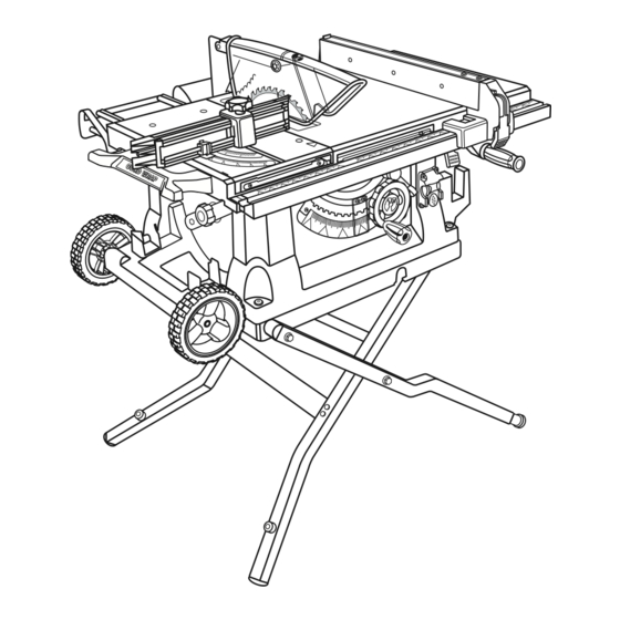
Page 10: Features
PRODUCT SPECIFICATIONS Blade Arbor ... 5/8 in. Blade Diameter ... 10 in. Blade Tilt ... 0˚ - 45˚ Net Weight without Leg Stand ... 61.5 lbs. Net Weight with Leg Stand ... 82.5 lbs. SPREADER LOCK SLIDING KNOB MITER TABLE OUTFEED SUPPORT MITER... - Page 11 BEVEL SCALE - The easy-to-read scale on the front of the cabinet shows the exact blade angle. BLADE - This saw is provided with a 36-tooth, 10 in. carbide- tipped blade. The blade is raised and lowered with the height/bevel adjusting handwheel. Bevel angles are locked with the bevel locking lever.
-
Page 12: Operating Components
SWITCH ASSEMBLY This saw is equipped with a switch assembly that has a built-in locking feature. This feature is intended to prevent unauthorized and possible hazardous use by children and others. -
Page 13: Tools Needed
For maximum performance, it is recommended that you use the 36-tooth, 10 in. carbide-tipped combination blade provided with your saw. Additional blade styles of the same high quality are available for specific operations such as ripping. Your local dealer can provide you with complete information. -
Page 14: Loose Parts
The following items are included with your table saw: A. Rip Fence ... 1 B. Large Blade Wrench ... 1 C. Small Blade Wrench ... 1 D. Elbow ... 1 E. Dust Bag ... 1 F. Handle Assembly ... 1 G. -
Page 15: Assembly
MOUNTING HOLES This tool comes mounted to a leg stand. If you chose to remove the leg stand, the table saw must be mounted to a firm supporting surface such as a workbench. Four bolt holes have been provided in the saw’s base for this purpose. Each of the four mounting holes should be bolted securely using 3/8 in. - Page 16 See Figure 7. To open (set-up) the leg stand: Step 1: With the saw table on end and standing to the side, use your left hand to pull the leg stand latch towards you. Step 2: Once the leg stand is released from the table saw base, ease the legs of the stand down.
- Page 17 Holding the leg stand firmly, pull the leg stand toward you until the leg stand and saw are balanced on the wheels. Push the saw to the desired location then either open the leg stand for immediate saw operation or store the saw in a dry environment.
- Page 18 CAUTION: To work properly, the saw blade teeth must point down toward the front of the saw. Failure to do so could cause damage to the saw blade, the saw, or the workpiece. NOTE: Arbor shaft has left hand threads.
-
Page 19: Operation
See Figure 14. Proper installation of the blade guard assembly means that the saw blade and spreader are in alignment. ALWAYS align the spreader to the saw blade prior to turning on the table saw. Lower the blade. Install the blade guard assembly to the mounting plate using the wing nut. -
Page 20: Avoiding Kickback
Kickback can occur when the blade stalls or binds, kicking the workpiece back toward you with great force and speed. If your hands are near the saw blade, they may be jerked loose from the workpiece and may contact the blade. Kickback can cause serious injury. -
Page 21: Cutting Tips
Cut the wood with the finish side up. Knock out any loose knots with a hammer before making the cut. Always provide proper support for the wood as it comes out of the saw. CROSS CUT RIP CUT MITER CUT... -
Page 22: How To Make A Featherboard
1/4 in. “finger” to be cut in the stock. Feed the stock only to the mark previously made at 6 in. Turn the saw OFF and allow the blade to com- pletely stop rotating before removing the stock. Reset the rip fence and cut spaced rips into the workpiece to allow approximately 1/4 in. - Page 23 TO POSITION THE SLIDING MITER TABLE See Figures 22- 23. A slide bolt is located on the front of the saw between the saw table and the front scale. When the arrows on both the saw table and sliding table are aligned, this bolt slides through the holes in both tables locking them into a fixed position.
-
Page 24: To Check Miter Base Parallelism
See Figures 24 - 25. Unplug the saw. Set saw up as if you were preparing to make a cut. Tighten rail clamps, miter locking clamps, lock knob, etc. Slide miter table (A) to the front of miter base (B) as far as it will go. - Page 25 Place one side of a framing square firmly against the miter fence and the other side against the saw blade. Using a flathead screwdriver, turn the eccentric screw until the miter fence and the blade are square.
- Page 26 TO USE THE RIP FENCE See Figure 30. Place the rear lip on the rear of the saw table and pull slightly toward the front of the unit. Lower the front end of the rip fence onto the guide surfaces on top of the front rail.
- Page 27 See Figure 31. The outfeed support slides to give the operator additional support for cutting long workpieces. With the table saw in the OFF position, stand behind the saw. Grasp the outfeed support with both hands and pull it until it is fully extended.
- Page 28 Mark beside one of the blade teeth at the front of the blade. Place a framing square even with the front of the saw table and the side of the saw blade as shown in figure 33. Turn the blade so the marked tooth is at the back.
-
Page 29: Making Cuts
Hold the workpiece firmly with both hands on the miter fence and feed the workpiece into the blade. When the cut is made, turn the saw off. Wait for the blade to come to a complete stop before removing the workpiece. - Page 30 Let the blade build up to full speed before feeding the workpiece into the blade. When the cut is made, turn the saw off. Wait for the blade to come to a complete stop before removing the workpiece.
- Page 31 Hold the workpiece firmly with both hands on the miter fence and feed the workpiece into the blade. When the cut is made, turn the saw off. Wait for the blade to come to a complete stop before removing the workpiece.
- Page 32 When the cut is made, turn the saw off. Wait for the blade to come to a complete stop before removing the workpiece.
- Page 33 Make sure the blade guard assembly is installed and working properly to avoid possible serious injury. Place a support the same height as the top of the saw table behind the saw for the cut work. Add supports to the sides as needed.
- Page 34 An optional dado throat plate (part number 0134010313) is required for this procedure. Do not use blades rated less than the speed of this tool. This saw is designed for use with a 6 in. stack dado (up to width of 5/8 in.). Do not use an adjustable dado on this saw.
-
Page 35: Adjustments
Blades coast after turn off. Possible serious injury can occur if hands come in contact with blade. The table saw has been adjusted at the factory for making very accurate cuts. However, some of the components might have been jarred out of alignment during shipping. Also, over a period of time, readjustment will probably become necessary due to wear. - Page 36 TO CHECK AND ALIGN THE SPREADER, SAW BLADE, AND BLADE GUARD ASSEMBLY See Figure 50. If the blade guard assembly is out of alignment with the saw blade, adjust the alignment of the blade guard assembly. The spreader must be aligned with the saw blade.
-
Page 37: Adjustments
TO SET THE BLADE AT 0° AND 45° See Figures 52 - 53. The angle settings of your saw have been set at the factory and, unless damaged in shipping, should not require set- ting during assembly. After extensive use, they may need to be checked. -
Page 38: Maintenance
WARNING: When servicing, use only identical replacement parts. Use of any other parts may create a hazard or cause product damage. WARNING: Always wear safety goggles or safety glasses with side shields during power tool operation or when blowing dust. If operation is dusty, also wear a dust mask. GENERAL MAINTENANCE Avoid using solvents when cleaning plastic parts. -
Page 39: Troubleshooting
Replace blade. Replace blade. Tighten all hardware. Reposition on flat surface. Adjust legs of leg stand. Check saw blade installation. Replace blade if necessary. Remount the rip fence. Clean and wax rails. Adjust clamp screw counterclockwise. Adjust clamp screw clockwise. -
Page 40: Troubleshooting
PROBLEM Saw does not make accurate 90˚ or 45˚ cuts. Height/bevel adjusting hand- wheel is hard to turn. Saw does not start. Blade makes poor cuts. Blade does not lower when turning height/bevel adjusting handwheel. Motor labors in rip cut. - Page 41 NOTES...
-
Page 42: Parts And Service
1-800-525-2579. • HOW TO OBTAIN CUSTOMER OR TECHNICAL SUPPORT: To obtain Customer or Technical Support please contact us at 1-800-525-2579. RYOBI is a registered trademark of Ryobi Limited used under license. ® 987000-087 1-18-07 (REV:00) OPERATOR’S MANUAL 10 in. TABLE SAW...