Table of Contents
Advertisement
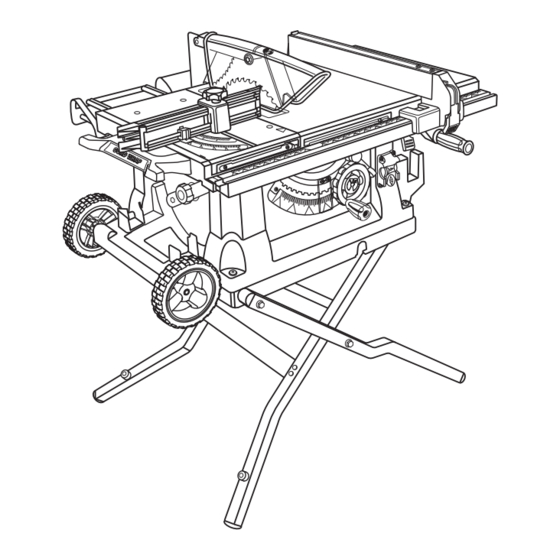
Your table saw
has been engineered and manufactured to our high standard for dependability, ease of operation, and
operator safety. When properly cared for, it will give you years of rugged, trouble-free performance.
wARNING:
To reduce the risk of injury, the user must read and understand the operator's manual before using
this product.
Thank you for your purchase.
SAVE THIS MANUAL FOR FUTURE REFERENCE
OPERATOR'S MANUAL
10 in. TAbLE SAw
bTS211
Advertisement
Table of Contents
Troubleshooting

Related Manuals for Ryobi BTS211


Summary of Contents for Ryobi BTS211
- Page 1 OPERATOR’S MANUAL 10 in. TAbLE SAw bTS211 Your table saw has been engineered and manufactured to our high standard for dependability, ease of operation, and operator safety. When properly cared for, it will give you years of rugged, trouble-free performance.
-
Page 2: Table Of Contents
The replacement power tool will be covered by the limited warranty for the balance of the two year period from the date of the original purchase. wHAT THIS wARRANTy COVERS: This warranty covers all defects in workmanship or materials in your RYOBI power ®... -
Page 3: General Safety Rules
GENERAL SAFETy RULES SECURE wORK. Use clamps or a vise to hold work when practical. It’s safer than using your hand and frees both wARNING: hands to operate tool. Read and understand all instructions. Failure to follow DON’T OVERREACH. Keep proper footing and balance all instructions listed below, may result in electric shock, at all times. -
Page 4: Specific Safety Rules
GENERAL SAFETy RULES bLADE COASTS AFTER bEING TURNED OFF. STAy ALERT AND EXERCISE CONTROL. Watch what you are doing and use common sense. Do not operate NEVER USE IN AN EXPLOSIVE ATMOSPHERE. tool when you are tired. Do not rush. Normal sparking of the motor could ignite fumes. - Page 5 SPECIFIC SAFETy RULES NEVER perform any operation “freehand” which means IF THE POwER SUPPLy CORD IS DAMAGED, it must using only your hands to support or guide the workpiece. be replaced only by the manufacturer or by an authorized Always use either the rip fence or miter fence to position service center to avoid risk.
-
Page 6: Symbols
SyMbOLS Some of the following symbols may be used on this tool. Please study them and learn their meaning. Proper inter- pretation of these symbols will allow you to operate the tool better and safer. Indicates a potential personal injury hazard. Safety Alert To reduce the risk of injury, user must read and understand Read Operator’s Manual... -
Page 7: Symbols
If you do not understand ing, use only identical replacement parts. the warnings and instructions in the operator’s manual, do not use this product. Call Ryobi customer service for assistance. wARNING: The operation of any power tool can result in foreign objects being thrown into your eyes, which can result in severe eye damage. -
Page 8: Electrical
ELECTRICAL EXTENSION CORDS SPEED AND wIRING Use only 3-wire extension cords that have 3-prong ground- The no-load speed of this tool is approximately 5,000 rpm. This speed is not constant and decreases under a load or ing plugs and 3-pole receptacles that accept the tool's plug. with lower voltage. -
Page 9: Glossary Of Terms
GLOSSARy OF TERMS Non-Through Cuts Anti-Kickback Pawls (radial arm and table saws) Any cutting operation where the blade does not extend A device which, when properly installed and maintained, completely through the thickness of the workpiece. is designed to stop the workpiece from being kicked back toward the front of the saw during a ripping operation. -
Page 10: Features
FEATURES PRODUCT SPECIFICATIONS Rating ..........120 V, AC only, 60 Hz Blade Arbor .............. 5/8 in. Input ..............15 Amps Blade Diameter ............10 in. No Load Speed ........5,000 r/min. (RPM) Blade Tilt ..............0˚ - 45˚ Cutting Depth at 0˚ ..........3-1/2 in. Net Weight without Leg Stand ...... -
Page 11: Know Your Table Saw
FEATURES KNOw yOUR TAbLE SAw LEG STAND - Attached to the table saw base, the leg stand opens and closes with ease. See Figure 2. MITER FENCE wITH ADJUSTING CLAMP KNOb - The The safe use of this product requires an understanding of fence attaches to the sliding miter table and can be angled the information on the tool and in this operator’s manual as for miter and compound miter cuts as well as straight cuts... -
Page 12: Operating Components
FEATURES OPERATING COMPONENTS wARNING: The upper portion of the blade projects up through the table and is surrounded by an insert called the throat plate. The ALWAYS remove the switch key when the tool is not in height of the blade is set with a handwheel on the front of use and keep it in a safe place. -
Page 13: Tools Needed
FEATURES bLADES wARNING: For maximum performance, it is recommended that you use the 36-tooth, 10 in. carbide-tipped combination blade Do not use blades rated less than the speed of this tool. provided with your saw. Additional blade styles of the same Failure to heed this warning could result in personal high quality are available for specific operations such as injury. -
Page 14: Loose Parts
LOOSE PARTS The following items are included with your table saw: Fig. 5 A. Rip Fence ..................................1 B. Large Blade Wrench ..............................1 C. Small Blade Wrench ..............................1 D. Elbow................................... 1 E. Dust Bag..................................1 F. Handle Assembly ................................ 1 G. -
Page 15: Assembly
ASSEMbLy UNPACKING wARNING: This product requires assembly. Do not lift the saw without help. Hold it close to your Carefully lift saw from the carton and place it on a level body. Keep your knees bent and lift with your legs, not work surface. - Page 16 ASSEMbLy TO INSTALL THE HANDLE ASSEMbLy set-uP tear doWn See Figure 6. Hold the nylon nut securely and turn the screw counter- clockwise to remove the nut completely. NOTE: Do not remove the screw from the handle or the washer from the end of the screw.
- Page 17 ASSEMbLy TO STORE THE TAbLE SAw ACCESSORIES See Figures 8 - 9. The table saw has two convenient storage areas (one on either side of the saw cabinet) specifically designed for the saw’s accessories. When not in use, store the accessories securely by snapping each accessory in place.
-
Page 18: To Check Saw Blade Installation
ASSEMbLy TO CHECK SAw bLADE INSTALLATION larGe See Figure 12. Blade WrencH CAUTION: To work properly, the saw blade teeth must point down toward the front of the saw. Failure to do so could cause small Blade damage to the saw blade, the saw, or the workpiece. WrencH NOTE: Arbor shaft has left hand threads. -
Page 19: Operation
ASSEMbLy TO INSTALL bLADE GUARD ASSEMbLy Flat See Figure 14. WasHer Proper installation of the blade guard assembly means that star WasHer the saw blade and spreader are in alignment. ALWAYS align the spreader to the saw blade prior to turning on the table WinG nut saw. -
Page 20: Avoiding Kickback
OPERATION AVOIDING KICKbACK wARNING: Always use the correct blade depth setting. The top of the blade teeth should clear the workpiece by 1/8 in. to Do not use any attachments or accessories not 1/4 in. recommended by the manufacturer of this tool. The use of attachments or accessories not recommended can ... -
Page 21: How To Make A Featherboard
OPERATION FEATHERbOARD holes in the featherboard. Positioning the featherboard will depend on the placement of the bolt and the position of the A featherboard is a device used to help control the sliding miter table on the rails. Place the washer on the bolt workpiece by guiding it securely against the table or fence. -
Page 22: Types Of Cuts
OPERATION TyPES OF CUTS See Figure 19. There are six basic cuts: 1) the cross cut, 2) the rip cut, 3) the miter cut, 4) the bevel cross cut, 5) the bevel rip cut, and 6) the compound (bevel) miter cut. All other cuts are combina- tions of these basic six. - Page 23 OPERATION TO CHANGE bLADE DEPTH Gullet See Figure 20. The blade depth should be set so that the outer points of the blade are higher than the workpiece by approximately 1/8 in. to 1/4 in. but the lowest points (gullets) are below the top surface.
- Page 24 OPERATION TO CHECK MITER TAbLE bASE PARALLELISM See Figures 24 - 25. Unplug the saw. Set saw up as if you were preparing to make a cut. Tighten rail clamps, miter locking clamps, adjusting clamp knob, etc. Slide miter table (A) to the front of miter base (B) as far as it will go.
- Page 25 OPERATION TO ADJUST THE MITER TAbLE bASE slidinG miter miter eccentric See Figure 26. taBle Fence screW Remember: Check all settings before loosening screws for the following procedures. Once screws have been loosened, these settings must be reset. Unplug the saw. ...
- Page 26 OPERATION Retighten hex nut, securing eccentric screw and quick- stop. Check your work. If the quick-stop is not at zero degrees, repeat above steps. wARNING: Fence To reduce the risk of injury, always make sure the rip fence scale is parallel to the blade before beginning any operation.
- Page 27 OPERATION TO USE OUTFEED SUPPORT See Figure 31. The outfeed support slides to give the operator additional support for cutting long workpieces. With the table saw in the OFF position, stand behind the saw. Grasp the outfeed support with both hands and pull it outFeed until it is fully extended.
- Page 28 OPERATION HEELING (PARALLELING) THE bLADE See Figures 33 - 35. FraminG square wARNING: The blade must be square so the wood does not bind resulting in kickback. Failure to do so could result in serious personal injury. Do not loosen any bolts for this adjustment until you have checked with a square and made test cuts to be sure adjust- ments are necessary.
-
Page 29: Making Cuts
OPERATION MAKING CUTS cross cut The blade provided with the saw is a high-quality combina- Place riGHt Hand tion blade suitable for ripping and cross cut operations. Care- on miter Fence fully check all setups and rotate the blade one full revolution Holder Here to assure proper clearance before connecting saw to power source. - Page 30 OPERATION MAKING A RIP CUT riP cut See Figure 38. Blade Fence wARNING: scale Make sure the blade guard assembly is installed and working properly to avoid serious possible injury. Set the blade to the correct depth for the workpiece. ...
- Page 31 OPERATION MAKING A bEVEL CROSS CUT VieWed From tHe Front, BeloW tHe taBle saW See Figures 40 - 41. HeiGHt/BeVel adJustinG HandWHeel wARNING: to loosen Make sure the blade guard assembly is installed and working properly to avoid possible serious injury. ...
- Page 32 OPERATION Position the workpiece flat on the table with the edge BeVel riP cut flush against the rip fence. Let the blade build up to full speed before feeding the workpiece into the blade. Blade scale Once the blade has made contact with the workpiece, anGled Fence use the hand closest to the rip fence to guide it.
- Page 33 OPERATION MAKING A LARGE PANEL CUT larGe Panel cut See Figure 44. Make sure the saw is properly secured to a work surface to riP Fence avoid tipping from the weight of a large panel. wARNING: Make sure the blade guard assembly is installed and working properly to avoid possible serious injury.
-
Page 34: Operation
OPERATION MAKING A DADO CUT Once all dado cuts are completed: Unplug your saw. See Figure 46. Reinstall the spreader/riving knife in the “up” position An optional dado throat plate is required for this procedure then install the blade guard and anti-kickback pawls. (see the Accessories section of this manual and check with the retailer where the table saw was purchased). -
Page 35: Adjustments
ADJUSTMENTS Rotate the blade by hand to make sure it turns freely. wARNING: Lower the saw blade and reinstall the throat plate. NOTE: Securely tighten throat plate screws. Do not allow Before performing any adjustment, make sure the tool is the throat plate to bow up above the table surface. - Page 36 ADJUSTMENTS TO CHECK AND ALIGN THE SPREADER, SAw screW (2) bLADE, AND bLADE GUARD ASSEMbLy See Figure 50. If the blade guard assembly is out of alignment with the saw blade, adjust the alignment of the blade guard assembly. The spreader must be aligned with the saw blade.
-
Page 37: Adjustments
ADJUSTMENTS TO SET THE bLADE AT 0° AND 45° Blade See Figures 52 - 53. comBination 0° adJustment The angle settings of the saw have been set at the factory square Bolt and, unless damaged in shipping, should not require set- ting during assembly. -
Page 38: Maintenance
MAINTENANCE wARNING: wARNING: When servicing, use only identical replacement parts. Do not at any time let brake fluids, gasoline, petroleum- Use of any other parts may create a hazard or cause based products, penetrating oils, etc., come in contact product damage. with plastic parts. -
Page 39: Troubleshooting
TROUbLESHOOTING PRObLEM CAUSE SOLUTION Excess vibration. Blade is out of balance. Replace blade. Blade is damaged. Replace blade. Saw is not mounted securely. Tighten all hardware. Work surface is uneven. Reposition on flat surface. Adjust legs of leg stand. Blade is warped. Check saw blade installation. -
Page 40: Troubleshooting
TROUbLESHOOTING PRObLEM CAUSE SOLUTION Saw does not make accurate Positive stops inside cabinet need Adjust positive stops. 90º or 45º cuts. adjusting (Bevel Cuts). Adjust the miter gauge. Miter gauge is misaligned (Miter Cuts). Height/bevel adjusting hand- Clean the gears or screw post. Gears or screw post inside wheel is hard to turn. - Page 41 NOTES...
-
Page 42: Parts And Service
HOW TO OBTAIN CUSTOMER OR TECHNICAL SUPPORT: To obtain Customer or Technical Support please contact us at 1-800-525-2579. RYOBI is a registered trademark of Ryobi Limited used under license. ® ONE wORLD TECHNOLOGIES, INC. 1428 Pearman Dairy Road, Anderson, SC 29625 Phone 1-800-525-2579 www.ryobitools.com...